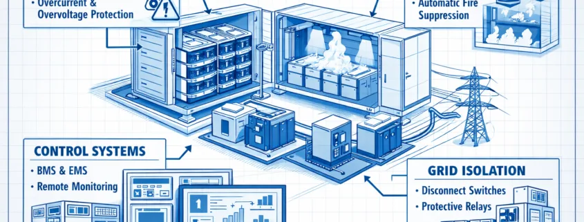
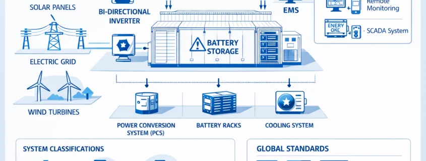
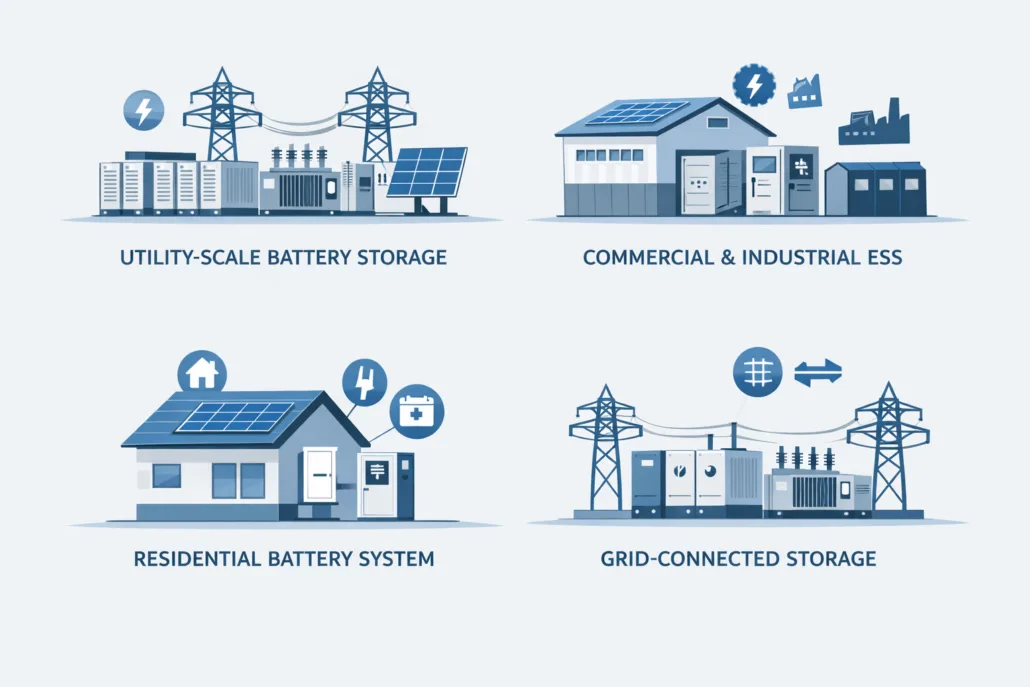
IEC 62933-5 safety standards define how electrical energy storage systems stay safe. They focus on system safety, battery risks, and grid connection safety. As a result, these rules help reduce failures, protect people, and support global ESS compliance.
IEC 62933-5 safety standards explain how to keep electrical energy storage systems safe. They cover risks linked to equipment, batteries, and grid connections.
As energy storage grows worldwide, safety becomes more critical. Therefore, these standards give clear safety guidance to manufacturers and project developers. In addition, they help regulators apply common rules.
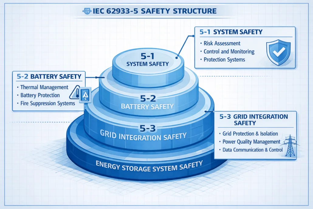
IEC 62933-5 uses a layered safety structure. Each layer addresses a different risk area. Together, these layers form a complete safety model.
Safety Layers Defined
IEC 62933-5-1: System-level safety
IEC 62933-5-2: Battery safety
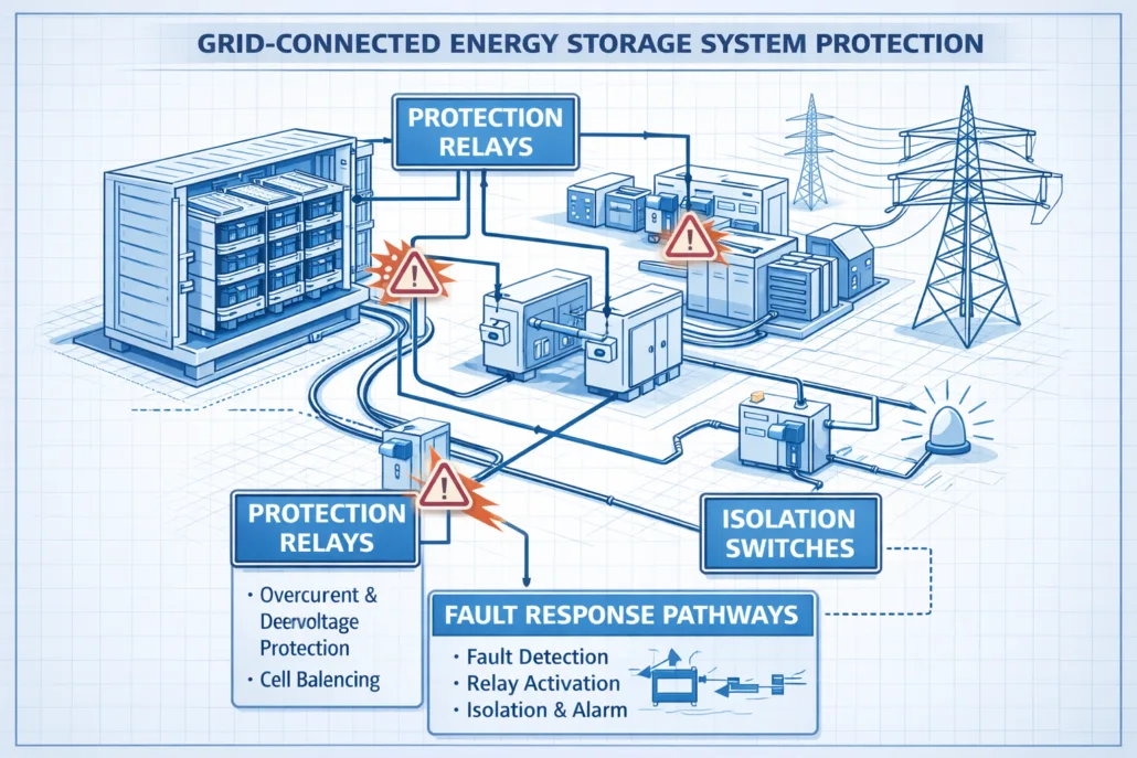
IEC 62933-5-3: Grid integration safety
Because each risk behaves differently, this structure improves clarity and control.
IEC 62933-5-1: General System Safety
Scope of IEC 62933-5-1
IEC 62933-5-1 defines basic safety rules for all ESS types. It applies to small and large systems alike.
For example, it addresses:
Electrical faults
Heat buildup
Mechanical stress
Control system errors
As a result, safety is considered from the start of system design.
Why System Safety Matters
Component safety alone is not enough. Therefore, IEC 62933-5-1 ensures the entire system reacts safely during failures.
IEC 62933-5-2: Electrochemical Battery Safety
Battery Risks Explained Simply
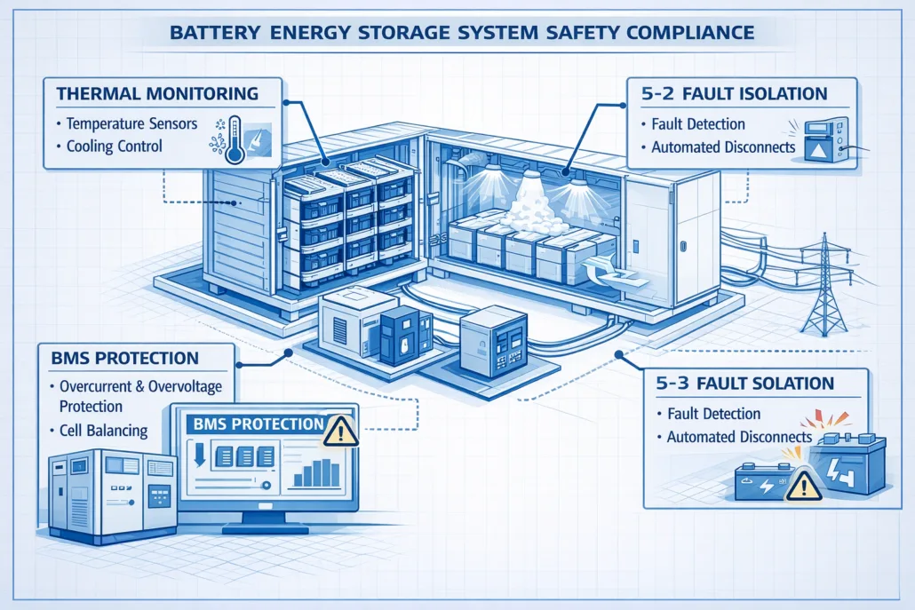
Batteries store large amounts of energy. However, failures can lead to fire or gas release. Because of this, IEC 62933-5-2 focuses only on battery-related risks.
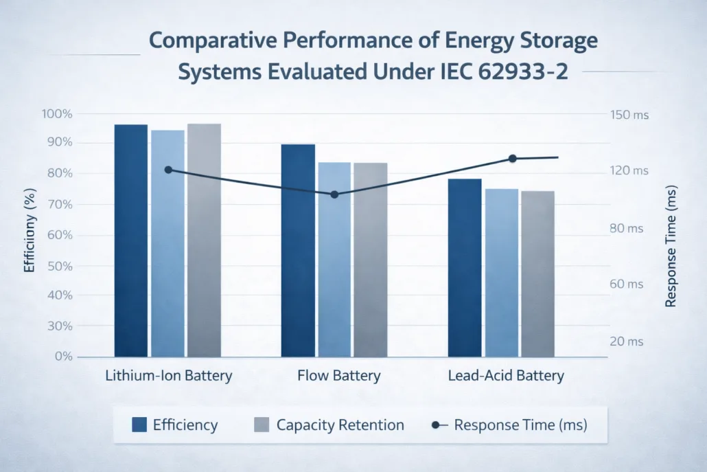
Thus, performance data often supports safety evaluations.
Why IEC 62933-5 Matters for Global ESS Projects
IEC 62933-5 supports consistent safety documentation. In addition, it helps align projects across regions.
Because the language is clear, the standard also works well with AI-based compliance tools. As energy storage expands, this consistency becomes essential.
Frequently Asked Questions
What is IEC 62933-5?
It is a safety standard for electrical energy storage systems.
Is IEC 62933-5 mandatory?
No. However, many utilities require it.
Does IEC 62933-5 replace UL standards?
No. Instead, it complements them.
Does it apply only to batteries?
No. It applies to all ESS technologies.
Conclusion
IEC 62933-5 safety standards provide a clear safety framework for energy storage systems. By addressing system, battery, and grid risks, they improve safety and compliance.
For modern ESS projects, IEC 62933-5 is essential.
Performance claims without standardized testing create uncertainty for utilities, investors, and regulators. IEC 62933-2 ESS Performance testing addresses this gap by defining uniform test methods for evaluating how an electrical energy storage system performs under real operating conditions.
Unlike marketing specifications, IEC 62933-2 focuses on measurable, repeatable, and technology-neutral performance indicators. These benchmarks enable objective comparison between systems and support transparent procurement, certification, and grid integration.
IEC 62933-2 defines standardized performance testing methods for Electrical Energy Storage Systems (ESS). It establishes measurable benchmarks for efficiency, capacity, response time, and operational behavior under controlled conditions. The standard ensures consistent performance evaluation across technologies, enabling fair comparison, bankability, and grid compliance for battery energy storage systems (BESS) and other ESS technologies.
Scope of IEC 62933-2
IEC 62933-2 applies to electrical energy storage systems, regardless of technology type. This includes:
Battery Energy Storage Systems (BESS)
Electrochemical storage
Hybrid ESS configurations
Grid-connected and behind-the-meter systems
The standard evaluates system-level performance, not individual components. This distinction is critical, as real-world ESS performance depends on the interaction between batteries, power conversion systems, controls, and thermal management.
Key Performance Metrics Defined in IEC 62933-2
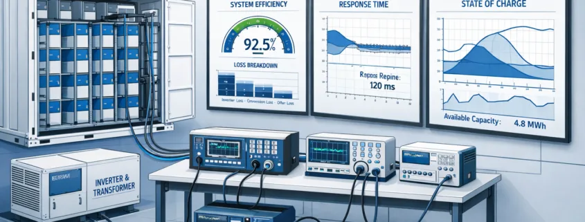
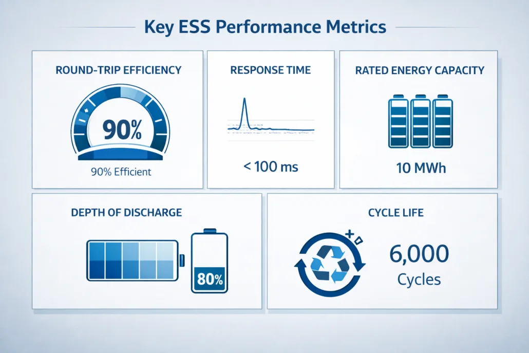
Core performance indicators evaluated during IEC 62933-2 testing.
IEC 62933-2 establishes a common set of performance indicators that reflect how ESS behave during operation.
1. Rated Energy Capacity
Rated energy capacity represents the usable electrical energy an ESS can deliver under defined conditions. The standard specifies how capacity must be measured to avoid inflated claims.
2. Round-Trip Efficiency
Round-trip efficiency measures the ratio of energy output to energy input over a full charge-discharge cycle. IEC 62933-2 standardizes test conditions to ensure fair efficiency comparisons across systems.
3. Response Time
Response time evaluates how quickly an ESS can react to control signals. This metric is essential for grid services such as frequency regulation and voltage support.
4. Power Capability
The standard assesses both continuous and short-duration power output, reflecting real operational constraints imposed by system design and controls.
5. Capacity Retention
Capacity retention tracks performance degradation over repeated cycles, providing insight into long-term operational reliability.
IEC 62933-2 ESS Performance Testing Methodology
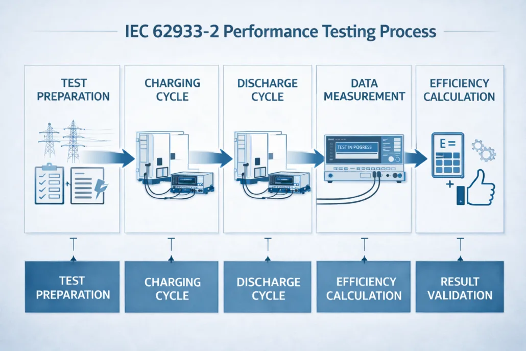
Step-by-step performance testing workflow defined under IEC 62933-2.
IEC 62933-2 defines structured testing procedures to ensure consistency and reproducibility.
Test Preparation
Before testing begins, the ESS must be configured according to defined operating parameters, including temperature, state of charge, and control settings.
Charging and Discharging Cycles
The system undergoes controlled charge and discharge cycles at specified power levels. These cycles simulate real operational use cases.
Measurement and Data Collection
All electrical parameters are measured at the point of connection (PoC), ensuring system-level accuracy rather than component-level approximation.
Result Validation
Collected data is analyzed against standardized calculation methods to validate performance metrics and eliminate test bias.
Laboratory Conditions for IEC 62933-2 Testing
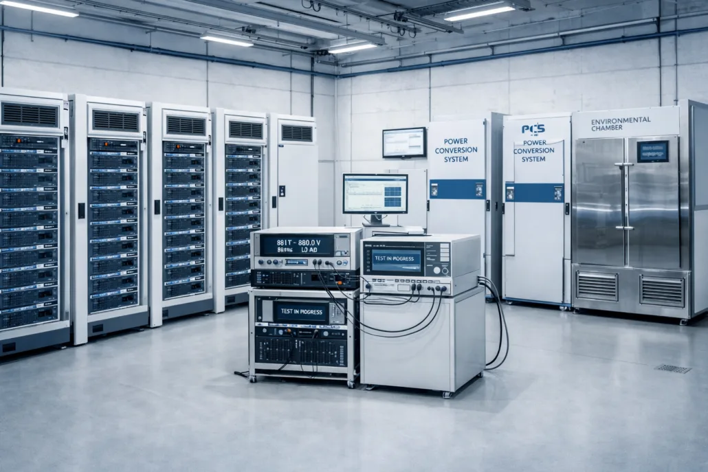
Controlled laboratory environment used for IEC 62933-2 ESS performance testing.
IEC 62933-2 emphasizes controlled laboratory environments to ensure reliable results.
Key laboratory requirements include:
Stable ambient conditions
Calibrated measurement equipment
Repeatable test configurations
Documented test procedures
These conditions ensure that performance results are reproducible and comparable across manufacturers and testing facilities.
Performance Benchmarking and System Comparison
One of the most valuable outcomes of IEC 62933-2 is benchmarking. By applying the same test methods, stakeholders can compare ESS performance objectively.
Benchmarking supports:
Technology selection decisions
EPC procurement evaluations
Utility grid qualification
Financial due diligence
Performance benchmarking under IEC 62933-2 reduces project risk and improves transparency across the energy storage value chain.
Relationship Between IEC 62933-2 and ESS Safety Standards
While IEC 62933-2 focuses on performance, it directly supports safety evaluation by identifying operational limits and stress conditions.
Performance data generated under IEC 62933-2 is often referenced during:
Together, these standards form a complete lifecycle framework for energy storage systems.
FAQ – IEC 62933-2 ESS Performance Testing
What does IEC 62933-2 measure?
IEC 62933-2 measures system-level performance, including efficiency, capacity, response time, and power capability of electrical energy storage systems.
Is IEC 62933-2 mandatory?
IEC 62933-2 is not legally mandatory, but it is widely required for compliance, certification alignment, and project bankability.
Does IEC 62933-2 apply only to battery systems?
No. It applies to all electrical energy storage systems, regardless of technology.
How is IEC 62933-2 different from component testing?
IEC 62933-2 evaluates the complete ESS at the system level, not individual batteries or converters.
Performance benchmarking comparison of ESS evaluated under IEC 62933-2.
Conclusion
IEC 62933-2 ESS Performance Testing provides the technical foundation for credible, transparent, and comparable ESS performance evaluation. By standardizing how energy storage systems are tested and benchmarked, the standard reduces risk, improves confidence, and accelerates global ESS adoption.
For manufacturers, EPCs, utilities, and regulators, IEC 62933-2 is a critical step toward safe, efficient, and bankable energy storage deployment.
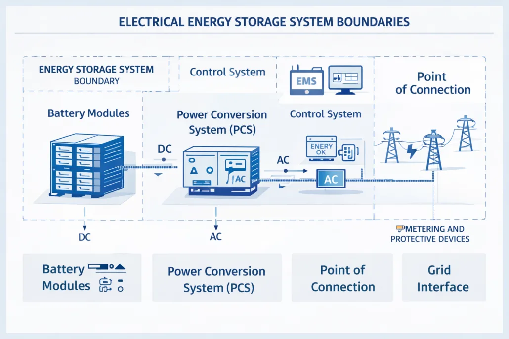
IEC 62933-1 is the foundational standard in the IEC 62933 series that defines terminology, system boundaries, and classification principles for Electrical Energy Storage Systems (ESS).
#image_title
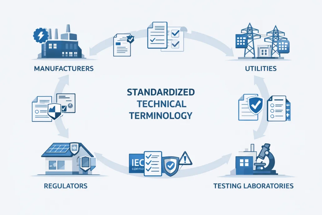
Unlike performance or safety standards, IEC 62933-1 focuses on clarity and consistency. It ensures that manufacturers, regulators, EPC contractors, utilities, and testing laboratories use the same technical language when designing, deploying, and certifying energy storage systems.
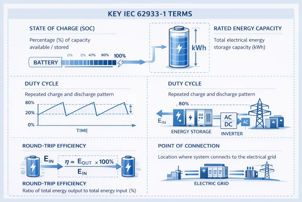
IEC 62933-1 establishes a standardized vocabulary and classification framework for Electrical Energy Storage Systems (ESS). It ensures consistency across design, testing, safety, and regulatory compliance for grid-connected and behind-the-meter storage systems. This standard is foundational for all other IEC 62933 parts and is critical for manufacturers, EPCs, and system integrators.
#image_title
⚙️ Why Standardized ESS Vocabulary Matters
Inconsistent terminology is a major cause of:
Certification delays
Safety misinterpretation
Grid interconnection failures
Contractual disputes
IEC 62933-1 eliminates ambiguity by defining clear system boundaries and uniform terminology across global markets.
Key Benefits:
Improves cross-border ESS compliance
Enables accurate safety risk assessments
Aligns performance testing methodologies
Supports AI-readable regulatory documentation
🔌 Classification of Electrical Energy Storage Systems
Types of energy storage systems
IEC 62933-1 classifies ESS based on functional role, application, and energy conversion method.
🔄 How IEC 62933-1 Supports Other IEC 62933 Standards
IEC Standard
Dependency on 62933-1
IEC 62933-2
Performance metrics definitions
IEC 62933-4
Environmental scope boundaries
IEC 62933-5-1
Safety terminology alignment
IEC 62933-5-2
Battery hazard classification
IEC 62933-5-3
Grid integration definitions
❓ FAQ – IEC 62933-1 Vocabulary Standard
What is IEC 62933-1 used for?
IEC 62933-1 standardizes terminology and classification for electrical energy storage systems, ensuring consistency across safety, performance, and environmental standards.
Is IEC 62933-1 mandatory?
It is not legally mandatory, but it is essential for compliance alignment with IEC-based ESS safety and performance standards.
Does IEC 62933-1 apply to BESS only?
No. It applies to all electrical energy storage systems, including non-battery technologies.
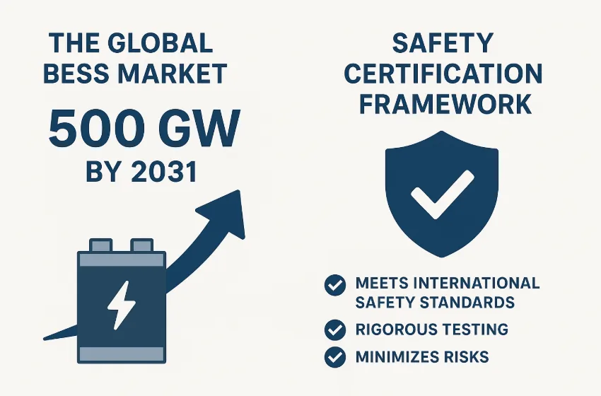
The global BESS market is projected to grow exponentially, reaching 500 GW by 2031. This forecast is a reflection of the world’s transition toward clean energy, electrification, and grid modernization. Battery Energy Storage Systems (BESS) are no longer niche technologies—they are becoming central to the stability and flexibility of modern energy networks.
But with such rapid deployment, BESS safety certification has emerged as a critical factor. Without strong certification standards, the risks of fire, explosion, or system failure increase. These risks not only threaten energy reliability but also create challenges for regulators, insurers, and investors.
In this article, we explore the drivers of global BESS market growth, the importance of safety certification, and the frameworks shaping the future of energy storage systems.
Why the Global BESS Market Is Growing So Fast
The energy storage systems projected 500 GW growth is being driven by a combination of technical, economic, and policy-related factors.
1. Renewable Energy Integration
Wind and solar are now the cheapest forms of new power generation worldwide. However, their variability creates challenges for grid operators. Battery energy storage systems solve this problem by storing excess energy and releasing it when demand rises.
2. Grid Modernization and Stability
Utilities are increasingly deploying BESS for peak shaving and load shifting, frequency regulation, and emergency backup. These applications make the grid more stable and resilient.
3. Commercial and Industrial Adoption
The C&I sector is also embracing storage. Businesses use BESS to cut peak demand charges, integrate renewable energy, and secure backup power through certified BESS installations.
4. Policy Support and Incentives
Governments are backing storage projects through subsidies, tax credits, and regulatory frameworks. For example, the U.S. Inflation Reduction Act provides tax benefits for energy storage projects, while the EU Green Deal is pushing for accelerated deployment.
The Risks of Rapid Expansion Without Certification
The market opportunity in certified BESS installations is immense. Yet, expansion without robust certification frameworks introduces serious risks.
Thermal Runaway – Poorly tested systems can overheat and cause chain-reaction fires.
Fire Hazards – Uncertified systems lack the proven ability to prevent or contain fires.
Grid Instability – Unsafe or poorly integrated BESS may destabilize the grid.
Investor Concerns – How certification improves investor confidence in BESS is by ensuring long-term reliability. Without it, projects face financing barriers.
These risks highlight why safety risks of battery energy storage without certification cannot be ignored.
Why Safety Certification Matters for BESS
As the global BESS market forecast to 2031 shows explosive growth, safety must be at the forefront. Certification ensures that BESS systems:
Meet UL 9540 certification for large-scale BESS to prove safe system integration.
Beyond safety, certification also drives global BESS market growth by creating trust.
How Certification Improves Investor Confidence in BESS
Reduces liability risks by ensuring compliance.
Streamlines project permitting and regulatory approval.
Enhances access to financing, as banks prefer certified projects.
Demonstrates compliance with regulatory requirements for battery energy storage systems 2031.
Without certification, large-scale projects could face costly delays, stricter insurance requirements, or outright rejection.
Global Trends in Energy Storage Certification and Testing
The global trends in energy storage certification and testing point toward stricter, more harmonized standards. Several developments are shaping the industry:
Harmonization of IEC and UL standards to reduce duplication.
Performance-based testing to reflect real-world conditions.
AI and digital twins for predictive safety assessments.
Third-party testing labs expanding capacity to handle growing demand.
As the market scales toward 500 GW energy storage forecast, these certification trends will define how quickly projects come online.
Looking Ahead: Balancing Growth With Safety
The global BESS market forecast to 2031 highlights a future of rapid scaling, but it comes with responsibility. The industry must prioritize best practices for BESS fire and explosion prevention to protect communities and maintain market trust.
Future growth will depend on:
Stronger collaboration between regulators and manufacturers.
By aligning market expansion with robust safety certification, the BESS industry can deliver safe, reliable, and sustainable storage solutions that support the global clean energy transition.
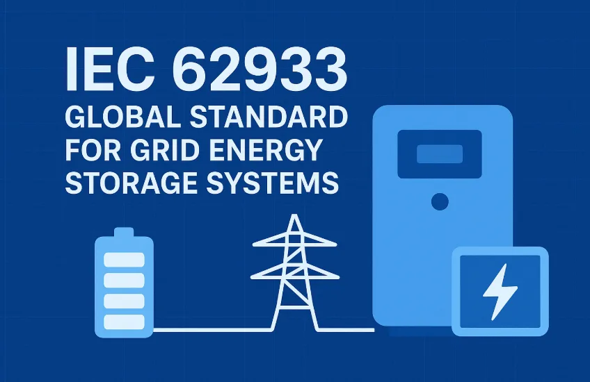
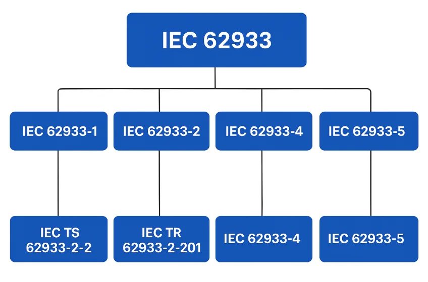
As renewable energy adoption grows, energy storage systems (ESS) have become critical for balancing supply and demand, improving reliability, and supporting grid resilience. To ensure safety, performance, and interoperability, the International Electrotechnical Commission (IEC) developed the IEC 62933 series, a set of globally recognized standards.
These standards guide manufacturers, developers, and policymakers in designing and deploying safe, efficient, and sustainable storage solutions.
Focuses on environmental assessment of energy storage technologies.
Considers carbon footprint, material use, and recycling practices.
Encourages sustainable deployment of large-scale ESS.
7. IEC 62933-4-4 – End-of-Life Management
Provides guidelines for decommissioning, recycling, and disposal of EES.
Promotes circular economy practices in the storage industry.
Reduces environmental risks associated with battery waste.
8. IEC 62933-5-1 – General Safety Considerations
Covers general safety requirements for stationary energy storage.
Includes electrical, chemical, mechanical, and fire safety aspects.
Ensures system safety across all technologies (batteries, flywheels, etc.).
9. IEC 62933-5-2 – Safety for Large-Scale EES
Focuses specifically on large battery energy storage systems (BESS).
Addresses thermal runaway prevention, emergency response, and system protection.
Critical for utility-scale storage projects.
10. IEC 62933-5-3 – Grid Integration Safety
Examines safety aspects during grid connection and operation.
Ensures ESS does not destabilize or endanger grid infrastructure.
Supports secure deployment in smart grids and microgrids.
Importance of IEC 62933 for the Industry
The IEC 62933 series provides:
Global Standardization – unifies practices worldwide.
Risk Reduction – prevents failures in high-risk ESS installations.
Sustainability – ensures safe end-of-life handling.
Investor Confidence – promotes compliance and long-term reliability.
Innovation Support – enables safe integration of emerging technologies like solid-state and hybrid storage.
Conclusion
The IEC62933 standard family is the backbone of global energy storage deployment. From general guidelines (IEC62933-1) to detailed safety (IEC62933-5-2) and environmental sustainability (IEC62933-4-4), it ensures storage systems are safe, efficient, and future-ready.
Adopting these standards is essential for manufacturers, developers, and regulators who aim to accelerate the clean energy transition while ensuring safety and reliability.
Battery Cycle Standards explain how battery life is measured; however, many datasheets are not clear. As a result, users often misunderstand real-world performance.
In reality, battery life is not a fixed number. Instead, it fluctuates based on usage and environmental conditions. Therefore, Understanding how DOD, SOH, and EOL work together is vital. Therefore, knowing these basics helps you pick the right battery for your needs
💡 Quick Summary: DOD vs SOH vs EOL
For those comparing battery specs, here is the essential relationship:
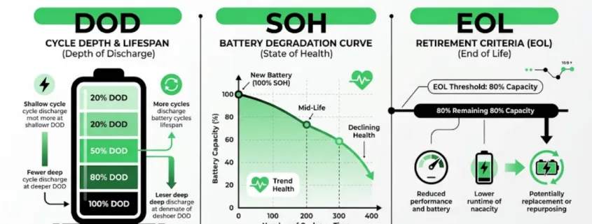
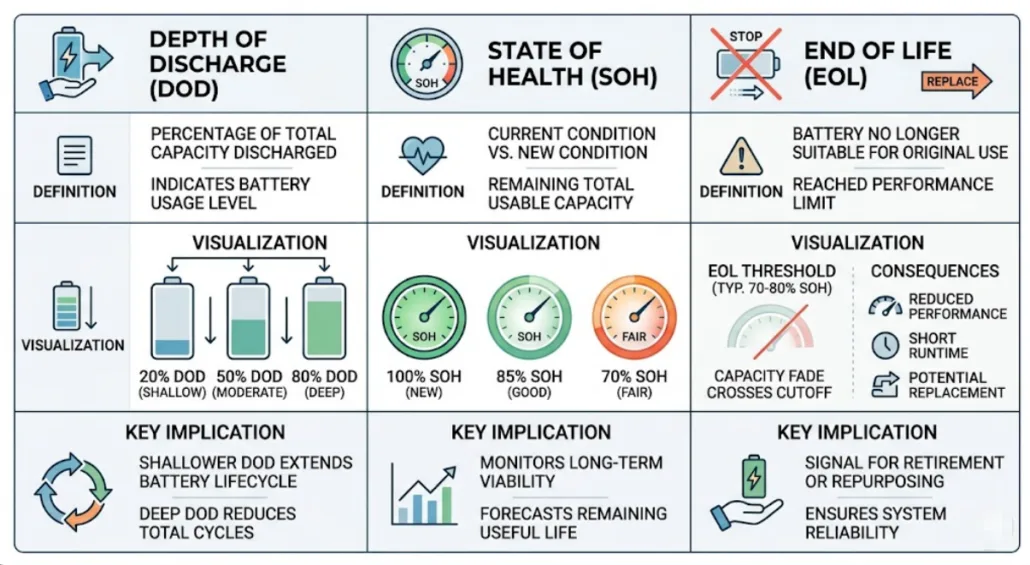
DOD (Depth of Discharge): How much energy you take out per cycle (e.g., 80%).
SOH (State of Health): How much total capacity the battery has left compared to when it was new.
EOL (End of Life): The “failure point” (usually 80% SOH) where the battery should be replaced.
The Standard: A battery rated for 6,000 cycles at 80% DOD means it can be used 6,000 times before its SOH hits the EOL limit.
What Are Battery Cycle Standards in Batteries?
Battery Cycle Standards measure how many charge and discharge cycles a battery can complete before its capacity drops to 70%–80%.
A battery cycle is formally defined as one full charge and discharge; nevertheless, real-world results depend on several critical factors. Specifically, variables such as temperature, charge rate, and Depth of Discharge (DOD) determine the actual longevity. Consequently, two batteries with identical ratings can perform very differently in different environments
For example:
Temperature
Charge rate
Depth of Discharge
What Is DOD in Battery Cycle Standards?
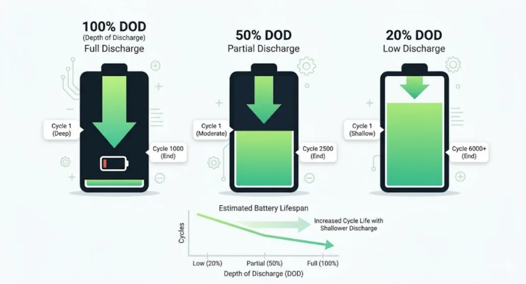
Depth of Discharge (DOD) indicates how much energy is cycled out of the battery; for instance, a 100% DOD means a full discharge, whereas a 50% DOD represents a half discharge.
For example:
100% DOD = full discharge
50% DOD = half discharge
While a higher DOD significantly increases internal stress and causes battery life to drop, utilizing a lower DOD conversely reduces wear on the cells and extends their longevity.
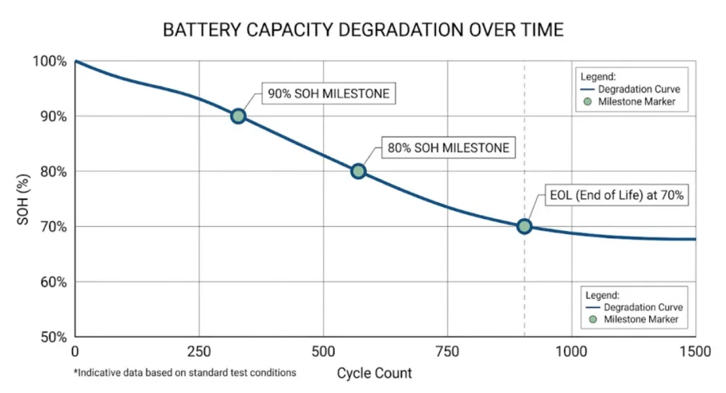
State of Health (SOH) shows remaining battery capacity.
For example:
100% SOH = new battery
80% SOH = reduced capacity
Over time, the SOH naturally decreases as the internal chemistry of the cells degrades. In addition to tracking wear, SOH serves as a vital indicator for warranty claims, since most manufacturers guarantee a specific capacity percentage over a set number of years.
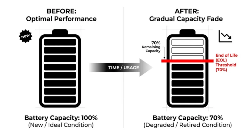
When SOH drops to 80% or 70%, that’s usually considered End of Life (EOL).
What Is EOL in Battery Cycle Standards?
End of Life (EOL) identifies the point when a battery is no longer considered reliable for its primary application.
In most cases, EOL is reached when the SOH drops to 70%–80%. Although the battery still works, its power is much lower. Consequently, you should replace it to keep your system safe and steady.
EOL = 70%–80% SOH
The battery still works. However, performance is lower. Therefore, it must be replaced.
Each metric is different. Therefore, you must use all three.
Why Battery Cycle Standards Are Different
Battery cycle standards differ because testing conditions and methods are not the same.
Different Testing Goals in Battery Cycle Standards
ome companies prioritize showing higher cycle numbers for marketing purposes, whereas others focus on providing realistic life expectations for heavy-duty use. Because of this variation in goals, the results across different brands can vary wildly. Therefore, it is crucial to verify if the cycles are rated at high or low temperatures.
Battery Cycle Life Depends on Conditions
Battery life depends on real conditions.
For example:
High temperature increases wear
High load adds stress
Fast charging speeds degradation
Therefore, results change.
Marketing vs Engineering in Cycle Standards
Some data is for marketing. Other data is for engineers.
Marketing materials often highlight the highest possible cycle numbers achieved under perfect lab conditions. In contrast, engineers focus on ‘usable’ life under heavy loads. Because of this discrepancy, it is important to look past the headline numbers and examine the testing parameters instead.”
Because of this, numbers may differ.
Same Battery, Different Ratings
It is common for a single battery to show multiple cycle values depending on the criteria used. Specifically, a manufacturer might list 6,000 cycles at 80% DOD while simultaneously claiming 8,000 cycles if the EOL is set to 70% SOH. Because both ratings are technically correct, you must compare the testing methods instead of just the final numbers.
Application-Based Battery Cycle Standards
Different industries use different metrics.
For example:
Solar uses EOL
EV uses SOH
Backup uses DOD
Therefore, standards change by use case.
Which Battery Cycle Standard Should You Trust?
EOL-based cycle life is the most reliable when tested under real conditions.
However, you must check:
DOD
Temperature
Charge rate
Without this, numbers can mislead.
Simple Rule for Battery Cycle Standards
Always check:
EOL at your real DOD
This gives the most accurate result.
How DOD Affects Battery Cycle Life
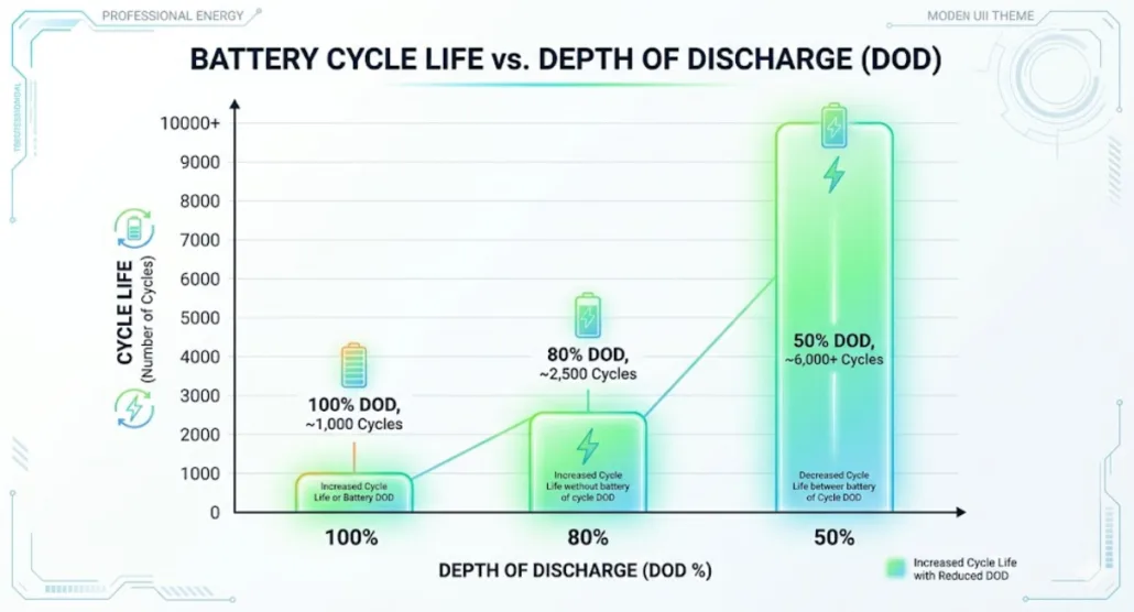
Higher DOD reduces battery life. Lower DOD increases it.
DOD
Cycle Life
100%
2,000–3,000
80%
3,000–5,000
50%
5,000–7,000
📊 Datasheet Cycle Life Calibration Tool
Input your battery’s specific datasheet baseline specs to simulate real-world environmental degradation.
📋 Step 1: Enter Datasheet Base Claims
⚙️ Step 2: Adjust Your Project Conditions
Your Operational DOD:80%
Ambient Cell Temperature:25°C
Calibrated Real-World Longevity Output
6,000 Cycles
~16.4 Years of Daily Use
⚠️ High ambient heat ($>35$°C) accelerates secondary SEI layer growth, heavily reducing chemical cycle ceilings.
*Calculated dynamically via Arrhenius rate parameters for cell aging and exponential Co-efficient models matching LFP structural chemistry metrics.
Therefore, lower DOD improves life.
Lab vs Real Battery Cycle Performance
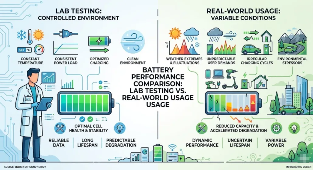
Lab tests typically use ideal conditions to establish a baseline; however, real-life performance is often quite different. For instance, ambient temperature fluctuations and varying discharge loads can add significant stress to the cells. As a result, the actual performance is usually lower than the theoretical ratings found on the datasheet. Consequently, users should plan for a margin of error when sizing their systems
Always compare DOD, SOH, EOL, and test conditions.
Start with your use case. Then check DOD. Next, review degradation.
Therefore, do not trust cycle numbers alone.
Battery Cycle Standards and Certifications
Battery standards are guided by:
International Electrotechnical Commission
Underwriters Laboratories
These groups define safety and testing rules.
Role of BMS in Battery Life
A Battery Management System (BMS) acts as the brain of the energy storage unit by controlling critical environmental and electrical factors.
Specifically, it manages the Depth of Discharge (DOD) and monitors internal temperatures to prevent thermal runaway. Furthermore, by regulating the charging current, the BMS ensures that the cells do not undergo excessive stress.
As a result, the overall battery life improves significantly, allowing the system to reach its full rated cycle potential.
Common Mistakes in Battery Cycle Standards
Many users make mistakes.
Many users make the mistake of trusting cycle numbers without investigating the underlying test conditions. For example, ignoring the DOD or missing the effects of high ambient temperatures can lead to premature system failure. Because of this lack of context, many buyers end up with the wrong battery for their specific climate or load requirements. Therefore, it is essential to review the full datasheet before making a final purchase
How to Improve Battery Life
While battery degradation is inevitable, you can extend your system’s lifespan easily by following a few best practices.
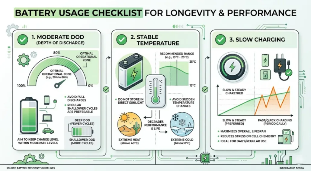
For instance, limiting your daily usage to a 70–80% DOD reduces the chemical strain on the Lithium-ion cells. In addition to managing discharge levels, keeping the ambient temperature stable and avoiding frequent fast charging will further preserve the SOH. Consequently, the battery will last much longer than a system that is constantly pushed to its operational limits
A battery cycle is one complete discharge and recharge of a battery’s rated capacity. It does not have to happen in a single sitting; for example, using 50% of your battery today and 50% tomorrow counts as exactly one full cycle.
How does DOD affect total battery life?
DOD (Depth of Discharge) has an inverse relationship with lifespan. Lowering your daily DOD significantly increases the total number of cycles a battery can perform. For instance, a Lithium (LFP) battery might achieve 3,000 cycles at 100% DOD but over 6,000 cycles if limited to 80% DOD.
What is the difference between SOH and SOC?
SOC (State of Charge): Tells you how much “fuel” is in the tank right now (0% to 100%).
SOH (State of Health): Tells you how much the “tank” has shrunk over time due to aging (e.g., 90% SOH means the battery can now only hold 90% of its original design capacity).
When should I replace my battery (EOL)?
The industry standard for End of Life (EOL) is 80% SOH. While the battery will still function below this point, it will drain faster and may struggle to power high-surge appliances. In solar storage, 80% is the typical threshold for warranty claims and reliable performance.
Final Takeaway
Battery Cycle Standards are not simple numbers. Instead, they depend on use and conditions.
Therefore, always check:
DOD
SOH
EOL
Always review full test conditions before comparing batteries.
⚡ Key Takeaways • A 100kW load run continuously (24/7) consumes 2,400 kWh per day. That daily energy figure is what drives solar and battery sizing. • Solar array size must be calculated for your worst realistic Peak Sun Hour (PSH) day, not your annual average — winter and cloudy-day sizing can be 2–2.5x larger than summer sizing. • Battery capacity depends on days of autonomy, Depth of Discharge (DoD), and round-trip efficiency — budget 3,000–10,000 kWh depending on backup duration. • The PCS/inverter is frequently undersized in DIY calculations — it must handle both the continuous 100kW draw and any surge/peak load, plus simultaneous charge and discharge in hybrid topologies. • LFP (LiFePO4) cells are the standard choice for stationary systems at this scale, rated for 3,000–5,000+ cycles at 80% DoD.
Planning solar panels and batteries to run a 100kW load around the clock? Sizing this correctly isn’t as simple as multiplying watts by hours, though.
Weather conditions, seasonal sunlight availability, cloudy-day derating, inverter sizing, and battery efficiency losses all factor in. Because of that, this guide walks through the full sizing process step by step, building toward a properly sized battery energy storage system (BESS) with formulas, worked examples, and a free interactive calculator.
📌 What You’ll Learn About Sizing for a 100kW Load
How to calculate required solar panel capacity for a continuous load
Why yearly weather data and Peak Sun Hours are critical to correct sizing
How to handle cloudy days and winter months without under-building
Battery sizing for different backup durations, DoD, and round-trip efficiency
How to size the PCS/inverter — the step most sizing guides skip
Battery chemistry, cycle life, and thermal management considerations at 100kW scale
Rough cost and payback framing so you can budget before requesting quotes
Example formulas and real-world worked values
🔧 Step 1: Understand Your 100kW Load
Let’s start with a 100kW load running 24 hours a day, every day.
100 kW × 24 hours = 2,400 kWh per day
That 2,400 kWh/day figure is your daily energy demand — it’s what solar and battery capacity are sized against.
If your load isn’t perfectly flat — for example, it dips to 60kW overnight and spikes to 130kW during a production shift — use the peak figure for PCS/inverter sizing. Use the daily kWh total instead (from a load profile or utility bill) for solar and battery sizing.
Averaging a variable load into a flat 100kW figure will, in short, undersize your inverter for the actual peak.
🌍 Step 2: Analyze Your Location’s Solar Irradiance for a 100kW Load
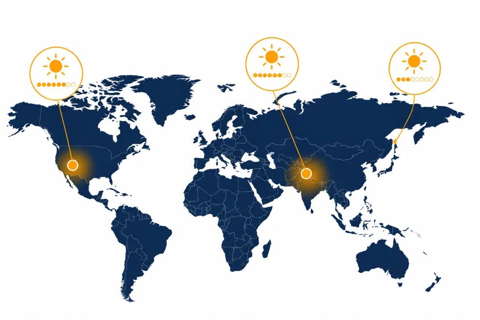
Your geographic location heavily influences how much sunlight you receive. Specifically, this is measured in Peak Sun Hours (PSH), the equivalent number of hours per day at 1,000 W/m² irradiance.
Location
Peak Sun Hours (avg)
Phoenix, USA
6.5 PSH
New Delhi, India
5.5 PSH
London, UK
2.8 PSH
👉 You can pull PSH data for your exact site from PVWatts (operated by the National Laboratory of the Rockies, formerly NREL), the NASA POWER Data Access Viewer, or commercial tools like Solcast. For a full breakdown of PSH by region and how it interacts with panel tilt, see our dedicated guides:
Sizing for the worst realistic case (cloudy-day PSH) rather than the annual average is, in fact, the single most common mistake in DIY sizing. In other words, it’s the difference between a system that works on a sunny July afternoon and one that keeps your load running in December.
🌥️ Why Consider Cloudy Days When Sizing a 100kW Load?
Even in a region with high annual irradiance, you’ll still, in fact, face stretches of poor sun exposure. For mission-critical applications, therefore, your system must:
Be oversized for worst-case scenarios, not average-case.
Include battery backup sized for 1–3 days of autonomy.
Use hybrid systems (generators or grid backup) where continuous uptime is non-negotiable.
❄️ Considerations for Winter Months
Winter brings three compounding effects:
Lower sun angles, which reduce effective irradiance on fixed-tilt arrays
Shorter daylight hours, which shrinks your PSH window
Snow cover in northern regions, which can fully block production for days
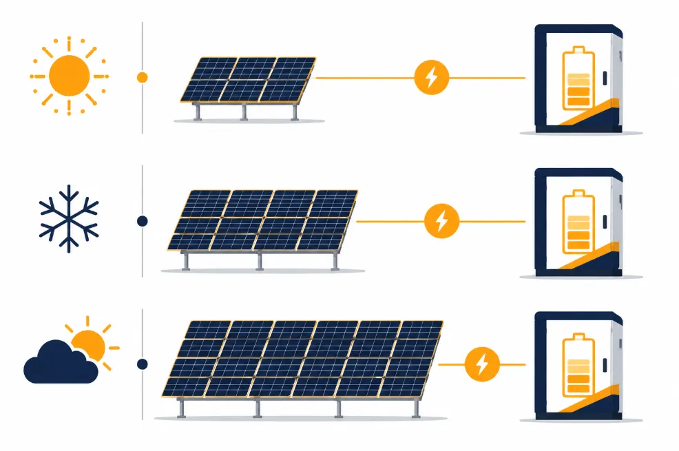
As a result, effective PSH drops and your dependence on stored energy or supplemental power increases. That’s exactly why the winter row in the Step 3 table above requires roughly 1.6x more solar capacity than the summer row.
⚡ Step 4: Size the Battery Energy Storage System for a 100kW Load
Ultimately, your BESS needs to store enough energy to power the load during non-sunny hours or outright weather/grid failures.
Formula:
Battery Capacity (kWh) = (Daily Load × Days of Autonomy) ÷ (DoD × Efficiency)
Daily Load = 2,400 kWh
Depth of Discharge (DoD) = 0.8
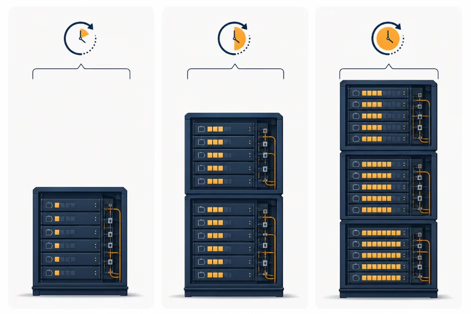
Round-trip Efficiency = 0.9
Backup Duration
Required Battery Capacity
1 Day
2,400 ÷ (0.8 × 0.9) ≈ 3,333 kWh
2 Days
4,800 ÷ (0.8 × 0.9) ≈ 6,667 kWh
3 Days
7,200 ÷ (0.8 × 0.9) ≈ 10,000 kWh
Note that these figures are usable energy requirements — rated (nameplate) capacity will need to be slightly higher once you account for BMS reserve margins and end-of-life capacity fade. For the difference between rated and usable capacity units, see Ah vs Wh Battery Capacity Explained, and for the general framework behind these backup calculations, see our Energy Storage Calculation Guide.
🔌 Step 5: Size the PCS / Inverter for Your 100kW Load (Often the Missing Step)
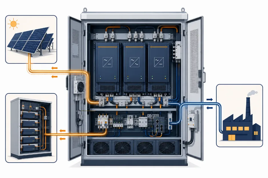
Solar array and battery capacity get most of the attention in sizing guides. However, the Power Conversion System (PCS) — the bidirectional inverter that moves power between panels, batteries, and load — is just as critical. In fact, it’s the component most DIY calculations undersize.
Specifically, your PCS needs enough continuous rating to handle the load, plus headroom for surge and simultaneous charge/discharge:
Continuous rating: must cover your 100kW continuous draw, not the average of a variable load profile.
Peak/surge rating: motor starts, compressor inrush, and HVAC cycling can spike 20–50% above continuous draw for a few seconds — undersized PCS units trip or clip during these events.
Simultaneous charge + discharge: in a hybrid solar + battery + load topology, the PCS may need to charge the battery from solar while discharging to load at the same time — size for the combined throughput, not just the larger of the two.
As a starting point, a reasonable figure for a 100kW continuous load is a 125–150kW PCS, though the correct number depends on your actual peak load profile and topology. For the functional breakdown of what a PCS does and how to evaluate one, see:
🔋 Battery Chemistry & Cycle Life for a Continuous-Duty 100kW Load
A 100kW load running 24/7 puts a battery through far more charge/discharge cycles per year than a typical backup-only installation. As a result, chemistry and cycle-life ratings matter more here than in a system that only discharges occasionally.
LFP (LiFePO4) is the standard choice for stationary systems at this scale: Tier-1 EV-grade LFP cells are typically rated 3,000–3,500 cycles at 0.5C / 80% DoD, with 120Ah-class prismatic cells often rated 3,500–6,000 cycles.
NMC offers higher energy density but lower cycle life and reduced thermal stability — generally a weaker fit for continuous-duty stationary storage than for space-constrained mobile applications.
Sodium-ion is an emerging alternative worth watching for cost-sensitive, cycle-heavy applications, though it currently trails LFP on energy density.
At 1–2 cycles per day, a 3,500-cycle-rated cell reaches end-of-life capacity (~80% of nameplate) in roughly 5–10 years. Therefore, factor this into both your battery oversizing margin and your long-term budget. For deeper comparisons:
🌡️ Thermal Management: Do You Need Liquid Cooling at This Scale?
A 3,000–10,000 kWh battery bank running near-continuous cycling generates meaningfully more heat than an occasional-backup system of the same size. Consequently, thermal management becomes a real design decision rather than an afterthought.
Air-cooled systems are simpler and cheaper, and remain viable for lower cycle-rate, moderate-climate installations.
Liquid-cooled systems hold tighter cell-to-cell temperature gradients, which matters directly for the cycle-life numbers above — sustained high temperatures accelerate capacity fade regardless of chemistry.
For continuous 0.5C–1C duty cycles in hot climates, liquid cooling is generally the safer long-term choice despite the higher upfront cost.
Install with adjustable tilt for seasonal optimization
TOPCon cells are, in fact, increasingly the default choice for higher-efficiency Tier-1 modules. For more detail, see our TOPCon Solar Cells guide on how they compare to standard PERC panels.
✅ Tips for Choosing Battery Cells for BESS
Use temperature-controlled (or liquid-cooled) enclosures for extreme climates
Choose Lithium Iron Phosphate (LFP) for safety and long cycle life at continuous-duty scale
Look for modular scalability so you can expand storage as load grows
Integrate with a proven BMS and EMS — don’t treat this as an afterthought
🔄 Hybrid Solutions for a Reliable 100kW Load
When powering a 100kW continuous load, therefore, it’s worth considering a hybrid setup:
Go fully off-grid: Solar + Wind + Battery — for redundancy in variable-weather regions
Add diesel backup: Solar + Battery + Diesel — for industrial backup where uptime is non-negotiable
Stay grid-connected: Solar + Grid + Battery — for grid-tied systems using the battery mainly for peak shaving and outage ride-through
💰 Estimating Total System Cost & Payback for a 100kW Load
Before requesting formal quotes, it helps to budget at a rough order of magnitude. Specifically, total installed cost scales with three line items: the solar array (per-watt installed cost), the battery bank (per-kWh installed cost), and the PCS/BOS/engineering package. Typically, the battery bank is the single largest line item at this scale given the 3,000–10,000 kWh range from Step 4.
Get exact per-watt and per-kWh figures from vendor quotes — these vary significantly by region, scale, and financing structure, so we intentionally don’t publish a single blended $/kWh figure here.
Payback period depends heavily on your alternative: offsetting diesel genset fuel and grid demand charges typically pays back faster than pure grid-tied offset in low-electricity-cost regions.
Model your specific numbers rather than relying on rule-of-thumb payback claims.
Battery for 2 days = 2,400 × 2 ÷ (0.8 × 0.9) ≈ 6,667 kWh
PCS sizing (per Step 5): 125–150 kW continuous, sized for the facility’s actual peak/surge profile
While static estimates give you a solid baseline, real-world engineering requires calculating system sizing interactively based on your specific geographical peak sun hours and target safety thresholds.
🧮 Interactive Solar & BESS Capacity Calculator
Use our professional sizing engine below to customize your numbers. Specifically, this tool automatically computes the balance between direct daytime consumption and the excess energy required to charge the battery bank for night or emergency runs.
☀️ Solar & BESS Capacity Calculator
📊 Recommended Sizing Results:
Daily Total Consumption: kWh/day
Required Solar Array Capacity: kWp
Required Battery Storage (BESS): kWh
Minimum Suggested PCS/Inverter: kW
🛠️ Sizing Definitions Explained
Daily Total Consumption (kWh): the total energy your system expends every day.
Required Solar Array Capacity (kWp): the nameplate rating of your panel configuration under Standard Test Conditions (STC), sized high enough to fill your BESS during operating hours.
Required Battery Storage (BESS, kWh): the gross storage capacity needed to survive weather downturns without exceeding safe Depth of Discharge (DoD).
PCS / Inverter Rating (kW): the continuous and surge power-handling capacity of the conversion system linking panels, batteries, and load — see Step 5 above.
📖 Recommended Sizing Resources for a 100kW Load
To fine-tune your inputs for the calculator above, explore our comprehensive technical guides:
Only if your load is flexible or you remain connected to the grid as a backstop. Otherwise, a continuous 100kW load with no grid connection and no battery has zero ride-through the moment the sun sets or a cloud rolls in.
Q: Should I oversize the battery or the solar array?
Both, in proportion to your climate. Specifically, cloudy regions need more solar oversizing to fill the same battery bank in fewer usable hours, while regions with frequent multi-day outages need more battery autonomy regardless of solar oversizing.
Q: What’s better — LFP or NMC batteries?
LFP is generally the safer, longer-cycle-life choice for stationary storage at this scale, while NMC’s higher energy density suits space-constrained mobile applications more than fixed installations.
Q: How big a PCS/inverter do I actually need for a 100kW Load?
Size for your actual peak draw plus surge headroom, rather than the 100kW continuous average. As a starting range, 125–150kW is reasonable, though you should pull your real load profile before finalizing (see Step 5).
Q: Do I need liquid cooling for a battery bank this size?
Not always — it depends on cycling frequency and climate. Continuous 0.5C–1C duty in hot climates benefits meaningfully from liquid cooling’s tighter thermal gradients, while lower cycle-rate systems in moderate climates can often stay air-cooled.
Q: How long will the battery bank last before it needs replacing?
Tier-1 LFP cells at 0.5C/80% DoD are typically rated 3,000–6,000 cycles. At roughly one full cycle per day, that’s a working life in the 8–14-year range before capacity fades to around 80% of nameplate, so budget your replacement schedule accordingly.
Q: Is grid-tied or off-grid better for a 100kW continuous load?
Grid-tied lets you undersize solar and battery relative to a true off-grid design, since the grid covers shortfalls. Off-grid or hybrid designs, on the other hand, are necessary wherever grid reliability can’t be trusted for a continuous critical load.
📌 Conclusion
Designing a solar + battery system for a 100kW load isn’t just about matching numbers. Rather, it’s about planning for the worst realistic day of the year, not the best.
In short, location-specific solar data, battery autonomy, PCS sizing, cell chemistry, thermal management, and cost all need to be part of your sizing strategy from the start, rather than bolted on after the array is already ordered.