IEC 62619 is the international safety standard that most industrial and commercial BESS suppliers get asked for first. Cell datasheets cite it, and procurement checklists demand it. But the standard rarely gets explained beyond a single bullet point in a longer certifications guide. So this article breaks down what it tests. It also covers what changed in the current edition, and how it fits alongside UL 1973 and IEC 63056.
Quick Answer IEC 62619:2022 is the international safety standard for rechargeable lithium cells and batteries in industrial applications. It covers stationary uses like BESS, UPS, and telecom backup, plus motive uses like forklifts and AGVs, but excludes road vehicles and consumer devices. The current edition added mandatory thermal runaway propagation testing, a formal BMS safety analysis, EMC testing, and overcurrent protection checks.
What Is IEC 62619?
IEC 62619 is published by the International Electrotechnical Commission’s Subcommittee 21A. Its full title is long, but in short: safety rules for lithium cells and batteries used in industry. The standard sets out the tests needed to show a lithium cell or battery is safe. This applies under both normal use and fault conditions.
The scope is industrial, not consumer. So it covers two broad groups:
Stationary applications — telecom power, uninterruptible power supplies (UPS), electrical energy storage systems, utility switching, and emergency power
Road vehicles are excluded. Where a conflict exists, standards written for automotive traction batteries take precedence instead (the IEC 62660 series). Consumer and portable devices sit under a separate standard, IEC 62133-2, rather than this one. For electrical energy storage systems, suppliers often pair IEC 62619 with a companion standard, IEC 63056. That standard adds rules built for EESS use. More on that distinction below.
The current edition is IEC 62619:2022 (Edition 2.0, published 24 May 2022). It replaced the original 2017 first edition. Europe adopts it through the EN and BS EN routes. Companies also often use the standard alongside CE marking for industrial battery systems.
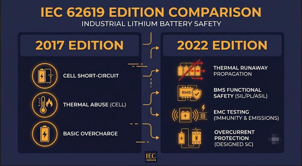
What Changed Between the 2017 and 2022 Editions
The second edition of IEC 62619 is a meaningfully stricter document. It is not a light refresh. Instead, the main additions concern system-level safety, not cell chemistry. This shift reflects how the industry moved from single-cell risk toward large multi-cell BESS deployments between 2017 and 2022.
Area
What Changed in the 2022 Edition
Thermal runaway propagation
Became a mandatory test. It was present informally since 2017 but is now formalized and expanded. A new laser-ignition method was added as an alternative trigger.
BMS functional safety
New rule for a formal safety analysis of the BMS. This references frameworks such as IEC 61508 (targeting SIL-2) or ISO 13849.
Overcurrent protection
New test checking that circuit protection triggers correctly under abnormal charge or discharge current.
Electromagnetic compatibility (EMC)
New rule showing BMS protection functions aren’t disrupted by outside electromagnetic interference.
System locks / fail-safe states
Clarified rules for preventing an unsafe automatic restart after a fault.
What the Standard Actually Tests
IEC 62619 testing runs across four categories: electrical, mechanical, environmental, and system-level. First, cell-level tests confirm the chemistry and build are safe. Then, system-level tests take over — newer and heavier in the 2022 edition. Together, they confirm the battery and its BMS respond correctly when something goes wrong.
Electrical Safety Tests
Overcharge — the test charges the cell or battery to roughly 1.5x rated voltage for an extended hold. No fire or explosion may occur. This shows the protection circuit or BMS cuts off correctly.
External short circuit — the test shorts the terminals through a low-resistance path. Surface temperature must stay well below thermal-runaway onset.
Forced discharge — the test discharges the battery below its minimum voltage, then checks for safe behaviour and a minimum capacity recovery on recharge.
Overcurrent protection (2022 addition) — shows the protection circuit activates correctly under abnormal charge or discharge current.
Mechanical and Environmental Tests
Crush — the test applies a defined force to the battery face. No fire or explosion may occur.
Free fall — drop testing across several orientations onto a hard surface. Checks for electrolyte leakage, fire, or explosion.
Vibration and shock — simulates transport and in-service stress without loss of function.
Temperature cycling — repeated cycling across a wide temperature band. A minimum capacity retention threshold applies at the end.
Thermal abuse — external heating beyond the maximum rated temperature. Evaluates the failure response.
System-Level Safety Tests
This is where the 2022 edition diverges most from 2017. Instead of behaving like a cell-safety spec, the standard now reads more like a system-safety framework.
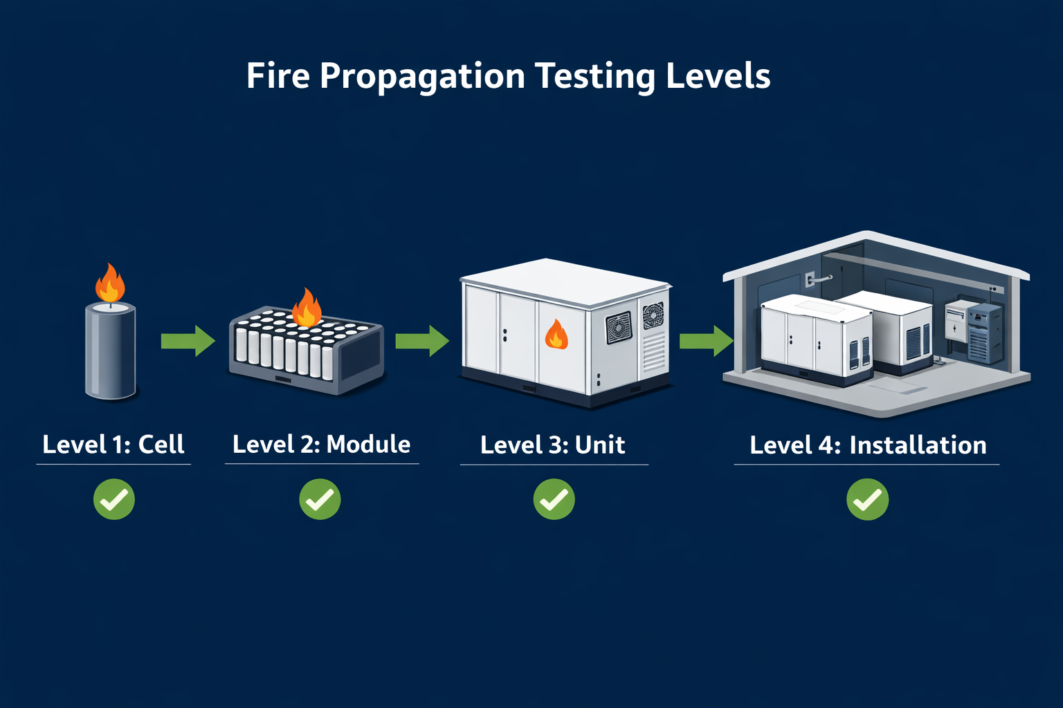
Thermal runaway propagation — the test deliberately drives a single cell into thermal runaway, then checks the failure doesn’t spread to neighbouring cells. This test matters most for large-format BESS design, since isolated cell failures inside a multi-megawatt-hour system count as a near-certainty over a 15-20 year service life. The goal is a contained, graceful failure, not zero failures.
BMS functional safety analysis — the test checks the BMS against a recognised safety framework. Triple monitoring of voltage, current, and temperature is typical at cell or module level, plus fast auto-disconnect on fault.
Communication fault handling — the system must enter a safe state if it loses BMS-to-host communication.
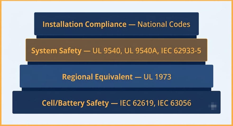
IEC 62619 rarely sits alone on a certification checklist. It’s one layer in a stack. That stack spans cell chemistry, system safety, installation, and transport. Here’s how it maps against the standards it’s most often confused with. This comparison draws on the IECEE CB Scheme documentation that governs how these certificates get issued and recognised worldwide.
US stationary and motive auxiliary power battery safety
Regional equivalent for the US market. Most North American stationary ESS installs require UL 1973 specifically, so global suppliers often hold both UL 1973 and this standard.
IEC 63056
Safety rules for secondary lithium batteries used in electrical energy storage systems
A companion standard, not a substitute. This standard sets the general industrial baseline, while IEC 63056 layers on EESS-specific rules. So ESS suppliers are often asked for both.
System- and grid-level safety for electrical energy storage systems
Sits above IEC 62619 in the stack. This standard certifies the cell or battery product, then IEC 62933-5 covers safety once that battery joins a full grid-connected system.
Safety of power converters (PCS/inverters) used in PV and ESS
Covers the inverter side, not the battery. This standard and IEC 62109 are complementary, since a full system needs certified batteries and a certified PCS.
Certification vs. Installation Compliance
One point worth remembering: this standard tests the battery product itself. It says nothing about whether an installation is legal in a given country. In Australia, for example, a certified battery module still has to separately satisfy AS/NZS 5139 for installation safety, AS/NZS 4777.2 for inverter compliance, and AS/NZS 3008.1.1 for cable sizing. So, product certification and installation compliance are two different layers. See our full breakdown in Australia’s New Battery Rules: The 2026 Compliance Stack.
Who Needs IEC 62619 Certification
Commercial & industrial (C&I) BESS makers and integrators
Utility-scale energy storage suppliers
Telecom backup power and UPS system makers
Industrial motive power — forklifts, AGVs, and similar equipment
Residential/home ESS suppliers — this standard is often part of the certification stack here too, though household rules sometimes point to IEC 60335 or IEC 63056 instead
Buyers should ask for cell-and-pack-level certification specifically. A component-level test report from one sub-supplier is not enough, since system integration, BMS logic, and enclosure design all affect whether certified parts stay safe once assembled.
Regional Recognition
Region
How It Is Recognised
International (CB Scheme)
50+ member countries accept test reports and certificates issued under the IECEE CB Scheme. This avoids duplicate testing when entering multiple markets.
Europe
Europe uses EN IEC 62619:2022 / BS EN IEC 62619:2022. Manufacturers commonly cite it for CE marking under the Low Voltage Directive.
India
IS 17855:2022 aligns closely with this standard. Large utility and industrial BESS tenders require it. Testing must happen at BIS-approved labs or accredited labs with a BIS agreement.
China
GB/T 36276 is the primary domestic standard for lithium-ion energy storage batteries. This standard is used as the international equivalent instead, for export-facing products.
Australia & New Zealand
One of the battery certifications commonly requested, alongside UL 1973 and UN 38.3. But it does not replace AS/NZS 5139 installation compliance — see our Australia battery rules hub for the full stack.
The Certification Process, in Brief
IEC 62619 certification typically runs through the IECEE CB Scheme:
Submit the application to an IECEE-recognised National Certification Body (NCB) with product docs, cell/battery specs, and BMS design details
The lab tests samples at an accredited CB Test Laboratory (CBTL) against the full test matrix
The lab issues a CB Test Report (CBTR) and CB Test Certificate (CBTC) on success
The CB certificate then converts into national certificates (CE, KC, SAA, and others). This is usually faster than a fresh national bid, since it draws on the existing CB test report
Timelines vary by scope and lab backlog. Full testing commonly runs several weeks to a few months. This depends on sample availability and whether early testing surfaces issues that need a redesign. So, ask suppliers for the CB Test Certificate itself and the full test report. Also confirm which edition, 2017 or 2022, it references. The 2022 edition is now the one expected for new product submissions.
IEC 62619 Compliance Checklist
Check the certificate references IEC 62619:2022, not the superseded 2017 edition
Request the full CB Test Report, not just the summary certificate
Verify the submission includes thermal runaway propagation results — this test matters most for multi-cell BESS safety
Check the BMS has a functional safety analysis (IEC 61508 SIL-2 or ISO 13849) in the submission
Check whether the application also needs IEC 63056 certification for the specific EESS use
For the US market, confirm whether the market requires UL 1973 too
Don’t treat this standard as a stand-in for system-level or installation rules. Check UL 9540/9540A, IEC 62933-5, or the local installation code separately
For transport, confirm the supplier holds UN 38.3 certification separately — this standard doesn’t cover it
Frequently Asked Questions
Is IEC 62619 mandatory?
IEC 62619 is a voluntary international standard, not a law. But it’s mandatory in practice across most industrial and utility-scale BESS procurement. Buyers, insurers, and financiers routinely list it as a minimum requirement, and some national tenders, including large BESS tenders in India, name it directly as mandatory.
Does IEC 62619 cover the whole BESS system or just the battery?
It covers the cell and battery product, including its BMS. But it does not cover the full assembled system. Enclosure design, fire suppression, inverter safety (IEC 62109), and grid-level integration (IEC 62933-5) all sit outside its scope.
What’s the difference between IEC 62619 and IEC 63056?
IEC 62619 sets general industrial safety rules for lithium cells and batteries. IEC 63056, meanwhile, is a companion standard with rules specific to electrical energy storage use. So suppliers commonly hold both together, not as alternatives.
Do I need both IEC 62619 and UL 1973?
Only if the product sells into both international and US markets. UL 1973 is what US utilities, AHJs, and insurers expect for stationary ESS, while IEC 62619 is the equivalent almost everywhere else. So global suppliers commonly hold both.
What was the biggest change in the 2022 edition?
The mandatory thermal runaway propagation test, plus the new rule for a documented BMS safety analysis. Both reflect the shift from single-cell risk thinking toward large, multi-cell stationary BESS.
⚡ Quick Answer: What Is a Battery Management System? A battery management system (BMS) is the electronic brain inside every lithium battery pack. It monitors cell voltage, current, and temperature in real time. It also protects cells from overcharge, over-discharge, short circuit, and thermal runaway. Furthermore, it estimates State of Charge (SOC) and State of Health (SOH). Without a BMS, a lithium battery is both unsafe and short-lived.
Every lithium BESS relies on a battery management system to run safely. This is true for a 10 kWh home install and a 10 MWh grid system alike. In both cases, therefore, the BMS is not optional — it sits between your cells and everything that can destroy them.
Yet the BMS is one of the most overlooked parts of any BESS purchase. Buyers focus on cell chemistry, capacity, and cycle life. Then they treat the battery management system as a given. That is a costly mistake.
A poor BMS, therefore, degrades good cells. A great battery management system, in contrast, extends the life of average cells. It is a lifespan management tool — not just a safety device.
This guide explains how a battery management system works, what it monitors, and how it balances cells. We also cover SOC and SOH calculation and show you how to evaluate a supplier’s BMS before you sign. For context on how the BMS interacts with cell chemistry, first read our LiFePO4 vs NMC battery comparison guide.
1. What Is a Battery Management System?
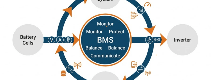
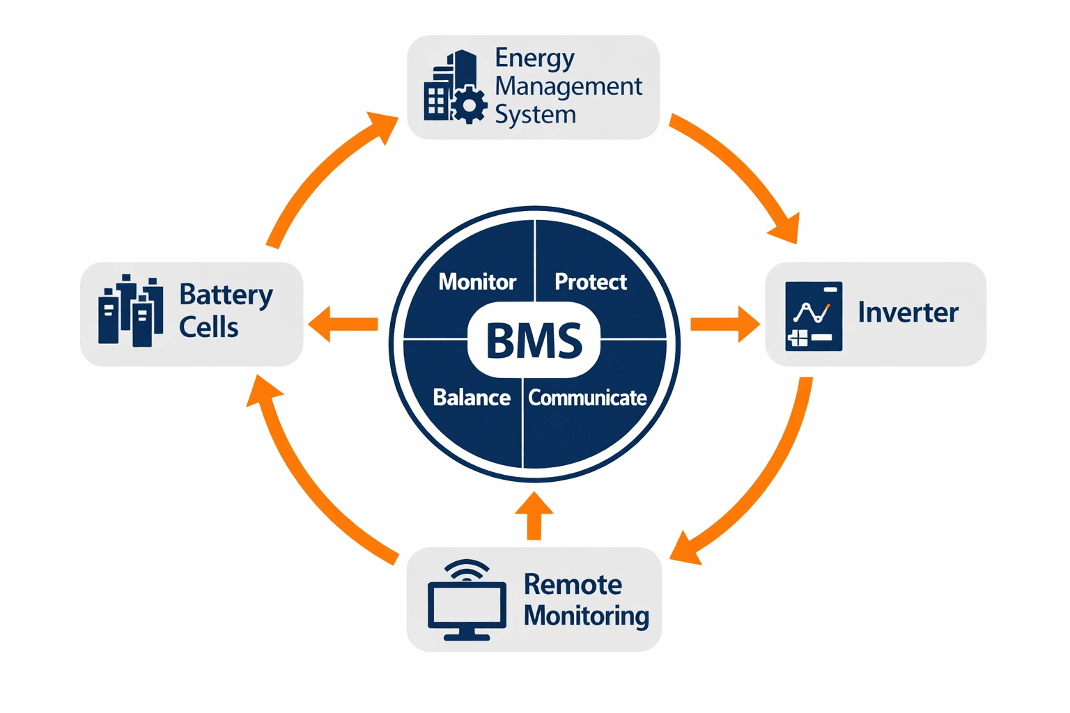
How a battery management system connects cells, inverter, EMS, and monitoring platform
A battery management system (BMS) is an electronic control unit built into a battery pack. Specifically, its job is to protect cells, measure their state, and report data to the rest of the system.
Think of the BMS as doing three jobs at once. First, it acts as a protection circuit — preventing electrical and thermal damage to the cells. Second, it is a measurement system — tracking voltage, current, temperature, SOC, and SOH. Third, it is a communication hub — sending live data to the inverter, EMS, and monitoring platform.
In a simple 12V residential pack, the BMS is a small PCB inside the module. In a commercial BESS, however, it manages hundreds of cells at once. The scale changes — but the core functions stay the same.
🔋 Why the Battery Management System Determines Lifespan Two identical cell packs with different BMS implementations deliver very different lifespans. Specifically, a BMS that allows cells to hit voltage limits, run hot, or drift out of balance will shorten cell life — regardless of the chemistry’s rated cycle count. The battery management system is, therefore, as important as the cells themselves.
2. Battery Management System Functions: The Seven Core Jobs
A well-designed battery management system performs seven distinct functions. Each one protects the battery in a different way. Together, furthermore, they determine whether your BESS is safe, efficient, and long-lived.
2.1 Cell Voltage Monitoring
The BMS monitors every individual cell voltage — not just overall pack voltage. This matters because cells in a multi-cell pack drift apart over time. Specifically, one weak cell can hit its limit before the others do.
For LiFePO4 cells, the safe range is 2.5V to 3.65V per cell. Going outside this range — even briefly — causes permanent capacity loss. So the BMS must, therefore, detect and respond to violations in milliseconds.
Voltage monitoring also underpins SOC estimation, which we cover in Section 5. Without accurate cell-level data, furthermore, everything else the BMS does becomes unreliable.
2.2 Current Monitoring and Overcurrent Protection
The BMS measures charge and discharge current using a shunt resistor or Hall-effect sensor. Specifically, this data serves four purposes:
Coulomb counting — integrating current over time to estimate SOC
Overcurrent protection — detecting short circuits and excessive discharge rates
C-rate enforcement — ensuring cells never charge or discharge faster than their rated speed
Power limiting — reducing available power as SOC drops or temperature rises
2.3 Temperature Monitoring
Temperature is one of the biggest drivers of battery degradation. Consequently, the BMS places sensors at multiple points — cell surfaces, busbars, and the enclosure. It uses this data to trigger cooling and reduce current.
It also halts charging below 0°C. Charging below freezing causes lithium plating. This is permanent anode damage that cannot be reversed.
For LiFePO4, the safe charging range is 0°C to 45°C. Discharge, however, runs across a wider range of -20°C to 60°C. The BMS enforces both limits automatically.
2.4 Overcharge and Over-Discharge Protection
These are the two most critical BMS protection functions. Overcharging a lithium cell causes irreversible changes in the cathode. Similarly, over-discharging collapses the anode. Both permanently reduce capacity.
The BMS prevents both by triggering a contactor disconnect when any cell breaches its voltage limit. This happens even if the pack’s overall voltage looks normal. One weak cell can hit its limit while others still have headroom. That is why cell-level monitoring is non-negotiable.
2.5 Short Circuit Detection and Response
A short circuit sends a massive current spike through the pack in milliseconds. Without protection, the heat this creates can trigger thermal runaway. As a result, the BMS detects the spike and opens the contactor in microseconds — before damage occurs. Learn more about how these critical failure paths are analyzed and mitigated in our engineering deep-dive on BMS Functional Safety, HARA, and FMEA.
Furthermore, sustained overcurrent protection prevents operation at damaging C-rates. This applies even without a sudden short circuit event.
2.6 Cell Balancing
Cell balancing is one of the most important long-term BMS functions. It keeps all cells at the same State of Charge. Without it, the weakest cell limits the entire pack — even though the others still have energy to give.
We cover passive vs. active balancing in detail in Section 4. The key point, however, is this: balancing quality directly affects how much rated capacity you can use over time. In other words, poor balancing means lost energy.
2.7 Communication and Data Reporting
A modern battery management system communicates with the inverter, EMS, SCADA, and remote monitoring platforms. In particular, the most common protocols include:
CAN bus — standard in high-performance BESS and automotive applications
RS485 / Modbus RTU — common in commercial and industrial storage
MQTT / TCP-IP — used for cloud monitoring and Battery Passport data exports
For a comprehensive look at how these networks function and talk to one another, read our complete guide on BESS Communication Protocols.
The BMS transmits SOC, SOH, cell voltages, temperatures, current, cycle count, and fault codes. Specifically, this data feeds dispatch decisions in the EMS and enables remote health tracking.
3. Battery Management System Architecture Options
BMS architecture scales with system size. Specifically, there are three implementation levels. Each one adds capability and complexity.
BMS Tier
Also Called
Scope
Typical Application
Cell-level BMS
CBMS
Monitors individual cells in one module
Residential storage under 30 kWh
Module BMS
Slave BMS / MBMS
Manages one group of cells in a module
C&I systems, EV battery packs
System / Master BMS
SBMS / Master BMS
Coordinates all modules in the full pack
Utility-scale BESS, multi-rack systems
Single-Level BMS (Residential)
In smaller systems — typically under 100 kWh — a single BMS manages all cells directly. This is a simple, low-cost architecture. Consequently, the BMS PCB sits inside the battery module and handles monitoring, protection, and balancing on its own.
However, as cell count grows, wiring becomes complex and processing load increases. Beyond a certain size, single-level BMS becomes impractical.
Master-Slave BMS (Commercial and Utility Scale)
In larger systems — typically above 100 kWh — a master-slave design is used. Each battery module has its own Slave BMS. It handles local cell monitoring and balancing. All Slave units then report to a central Master BMS, which coordinates the full system.
The Master BMS aggregates data from all modules and manages system-level protection. Furthermore, it communicates with the inverter and EMS. As a result, this architecture scales well to multi-megawatt-hour systems.
⚠️ Key Evaluation Point: Master-Slave Independence In a quality master-slave battery management system, each slave module should protect its own cells independently — even if communication with the master is lost. A BMS where cell protection depends entirely on the master, however, creates a single point of failure. Therefore, always ask: what happens to cell-level protection if the master controller fails?
🔗Read Also:For a deeper comparison including wiring protocols and wireless BMS, see ourfull BMS architecture guide
4. Cell Balancing in a Battery Management System: Passive vs. Active
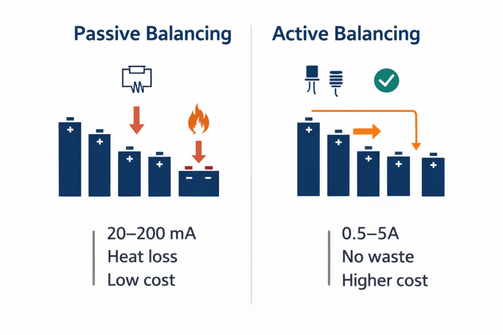
Passive balancing dissipates excess charge as heat. Active balancing transfers charge between cells electronically.
Why Cells Need Balancing
No two lithium cells are identical. Manufacturing tolerances mean cells leave the factory with slightly different capacities. Moreover, temperature gradients within a pack cause some cells to age faster. Self-discharge rates also vary slightly between cells.
[!NOTE] For the manufacturing step that happens before balancing even starts, see our cell matching guide.
Over time, cells drift apart in State of Charge. The cell with the lowest SOC determines when discharge must stop. Similarly, the cell with the highest SOC determines when charging must stop. If cells are out of balance, the weakest cell constrains the entire pack — even though the others still have capacity.
The BMS corrects this drift through balancing. As a result, all cells stay at the same SOC and the full rated capacity remains usable.
Passive Balancing: Simpler and More Common
Passive balancing is, specifically, the most common approach. The BMS bleeds off excess charge from higher-SOC cells as heat through a resistor. It keeps doing this until, eventually, all cells match the lowest cell.
Advantages: Low cost, simple, reliable, and well-proven across millions of systems.
Disadvantages: Energy is wasted as heat. Balancing current is typically low (20–200 mA), so it is slow. In large packs with heavy imbalance, furthermore, passive balancing cannot keep up.
Passive balancing is, therefore, best suited to residential and small commercial systems. It works particularly well where cell quality is high and cycle frequency is moderate.
Active Balancing: Better for High-Cycle Systems
Unlike passive balancing, active balancing transfers energy from higher-SOC cells to lower-SOC cells using inductive or capacitive circuits. Energy is not wasted — instead, it is redistributed within the pack.
Advantages: No energy waste. Higher balancing currents (0.5–5A) mean faster correction. Better long-term capacity retention in high-cycle applications.
Disadvantages: Higher cost and more complexity. There are, therefore, more potential failure points in the balancing circuitry.
Active balancing is, therefore, best specified for utility-scale BESS, frequency regulation, and systems designed for 15+ year lifespans where long-term capacity retention is critical to ROI.
Factor
Passive Balancing
Active Balancing
How it works
Burns excess charge as heat via resistor
Transfers charge between cells electronically
Energy efficiency
Low — energy wasted as heat
High — energy redistributed within pack
Balancing speed
Slow: 20–200 mA typical
Fast: 0.5–5A typical
System complexity
Simple and reliable
More complex, more failure points
Cost
Low
Higher (2–5x passive)
Best for
Residential and small C&I (under 500 kWh)
Utility-scale and high-cycle BESS (over 500 kWh)
🧠 Interactive BMS Balancing Simulator
Simulate how a BMS manages individual cell drift and balances a 4-cell LFP pack.
🔋 Current Cell Status (Target: 3.40V)
Cell 1 (Balanced):3.40V
Cell 2 (High Spike / Overcharge Risk):3.55V
Cell 3 (Balanced):3.40V
Cell 4 (Weak / Low Capacity):3.25V
⚡ Step 2: Trigger BMS Balancing Strategy
BMS Operational Status
Status: Standby (Imbalance Detected)
Pack efficiency is restricted by Cell 4. Select a balancing method above to view the electronic correction process.
*Visualized example based on a standard 4S LiFePO4 configuration operating near upper knee voltage thresholds.*
5. How the Battery Management System Estimates SOC (State of Charge)
Essentially, SOC is the fuel gauge of your battery. It shows how much energy is stored, expressed as a percentage of full capacity. Accurate SOC is essential for safe operation and efficient dispatch.
Importantly, SOC cannot be measured directly. Instead, it must be estimated from measurable quantities — voltage, current, and temperature. The BMS uses one or more algorithms to do this. Each method has distinct strengths and trade-offs.
Method 1: Open Circuit Voltage (OCV) Lookup
Specifically, this is the simplest SOC estimation method. When a battery has rested for 30–60 minutes, its Open Circuit Voltage maps to SOC via a lookup table. The table is built from cell characterisation tests.
However, OCV works poorly for LiFePO4. LFP has a very flat voltage curve between 20% and 80% SOC. Small voltage changes correspond to large SOC swings in this region. As a result, OCV-based SOC is inaccurate during normal operation. It is mainly useful for setting the initial estimate after a long rest period.
Method 2: Coulomb Counting
Coulomb counting integrates current over time. It tracks how much charge has entered or left the battery. As a result, it is the most widely used SOC method in real-time operation.
Coulomb counting is accurate over short periods. However, it accumulates error over time due to sensor tolerances, temperature effects, and small unmeasured currents. Without periodic recalibration, the estimate drifts.
Best practice: In practice, reset SOC to 0% or 100% when the battery hits its cutoff voltage. These anchor points correct accumulated drift effectively.
Method 3: Extended Kalman Filter (EKF)
The Extended Kalman Filter is the most accurate SOC method available. It combines Coulomb counting with a mathematical model of the battery’s electrochemical behaviour. Consequently, it corrects the estimate continuously based on the gap between model prediction and actual voltage.
EKF handles LFP’s flat voltage curve far better than OCV. It adapts in real time to temperature changes, aging effects, and varying loads. Furthermore, premium BMS platforms from Texas Instruments, Analog Devices, and Orion BMS use EKF or adaptive Kalman variants.
The trade-off: EKF requires significant processing power and a well-characterised cell model. It is, consequently, computationally demanding and needs careful tuning for each chemistry.
SOC Method
Accuracy
LFP Suitability
Typical Use
Open Circuit Voltage
±5–10% in flat region
Poor — flat curve limits accuracy
Initial SOC after rest period only
Coulomb Counting
±3–5% short term, drifts over time
Good for real-time tracking
Residential and most C&I systems
Extended Kalman Filter
±1–2% with good cell model
Excellent — handles flat curve well
Utility-scale BESS and precision apps
6. How the Battery Management System Tracks SOH (State of Health)
State of Health (SOH) measures how much of a battery’s original capacity remains. A new battery starts at 100% SOH. Each cycle causes a small, permanent capacity loss. Consequently, the BMS tracks this degradation over the system’s lifetime.
Specifically, SOH is defined as: SOH (%) = (Current Capacity ÷ Original Rated Capacity) × 100.
Notably, End of Life (EOL) is declared when SOH drops to 80% — or 70% in some industrial applications. For more on how EOL thresholds work in practice, see our Battery Cycle Standards guide.
How SOH Is Estimated Over Time
SOH cannot be measured with a single reading. Instead, the BMS builds up estimates using several data sources accumulated over time:
Capacity fade tracking — comparing measured full-charge capacity against original rated capacity
Internal resistance measurement — resistance increases as cells age; higher resistance correlates with lower SOH
Cycle counting — simple but imprecise; does not account for partial cycles or varying depth of discharge
Incremental Capacity Analysis (ICA) — an advanced technique that analyses the dV/dQ curve to detect electrochemical aging signatures
SOH Logging and Warranty Compliance
Accurate SOH logging matters for two reasons. First, it supports warranty claims. Most BESS warranties guarantee a minimum SOH at a set cycle count — for example, 80% SOH at 6,000 cycles. The BMS is the primary evidence source for any claim.
Second, SOH logging is becoming a regulatory requirement. The EU Digital Battery Passport, mandatory from February 2027 under EU Batteries Regulation 2023/1542, requires SOH history, cycle count, and energy throughput data. The battery management system is the primary source for all of it.
📊 Battery Management System SOH and Warranty Compliance A BMS that accurately logs SOH over time — with timestamped cycle data — makes warranty claims straightforward. A BMS without proper SOH logging, however, creates disputes. Always ask what SOH data is recorded, how long it is stored, and in what format it can be exported.
7. Battery Management System Requirements: LiFePO4 vs. NMC
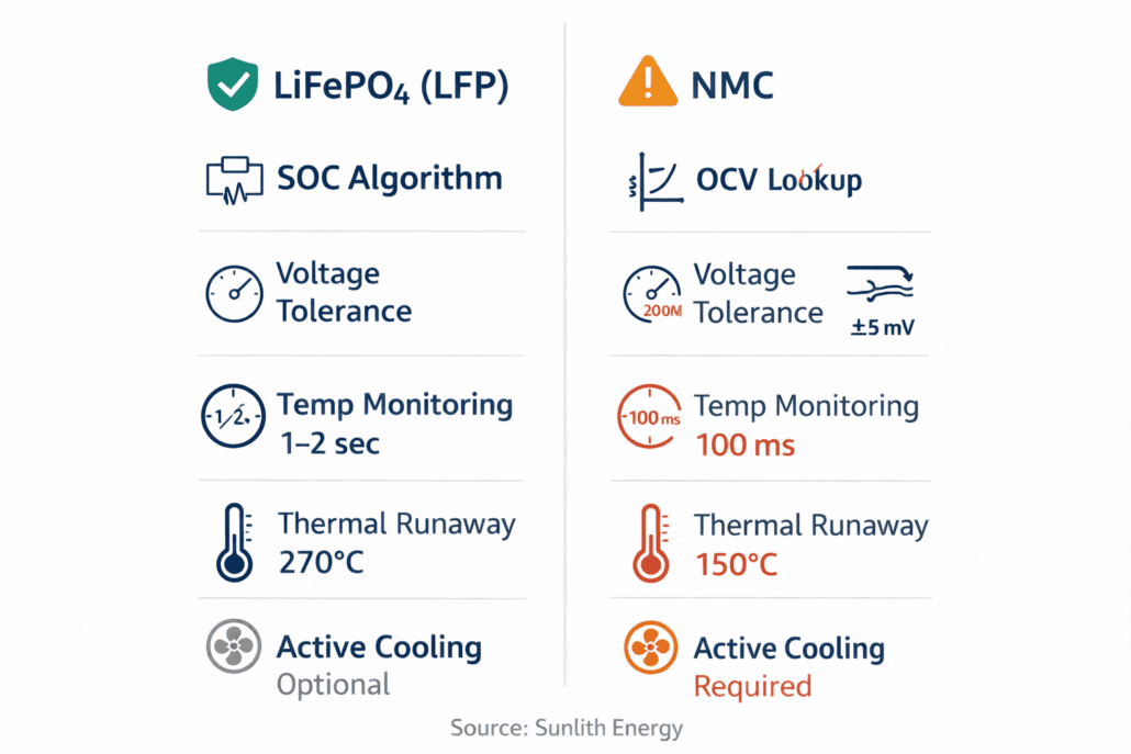
LFP and NMC place very different demands on the battery management system — especially for SOC estimation and thermal monitoring speed
LiFePO4 (LFP) and NMC place very different demands on the battery management system. Understanding these differences, therefore, helps you confirm that a supplier’s BMS is genuinely designed for their stated chemistry. A BMS reused from a different application, for instance, will often perform poorly on LFP.
SOC Accuracy: Why LFP and NMC Differ
LFP’s flat voltage curve — discussed in Section 5 — makes SOC measurement significantly harder than NMC. An NMC cell’s voltage, in contrast, changes continuously and predictably with SOC. LFP, however, sits near 3.2V–3.3V across 80% of its SOC range. As a result, OCV lookup is unreliable for LFP in real-time operation.
Consequently, a BMS designed for NMC but deployed on LFP cells will show poor SOC accuracy. This leads to premature shutdowns or unexpected overcharge events. Always, therefore, confirm the BMS SOC algorithm is specifically calibrated for LFP chemistry.
Thermal Monitoring: NMC Is More Demanding
NMC cells are more temperature-sensitive than LFP. Specifically, they degrade significantly above 35°C and have a lower thermal runaway threshold — 150°C to 210°C versus 270°C to 300°C for LFP.
As a result, an NMC battery management system requires:
Temperature monitoring intervals of every 100–500ms — versus every 1–2 seconds for LFP
Faster thermal runaway response — disconnection in milliseconds when temperature spikes
More temperature sensors per module — to catch hot spots before they spread
Integration with active liquid cooling systems — which are common in NMC BESS
NMC cells are damaged more easily by small voltage excursions above the charge cutoff. As a result, a BMS protecting NMC must enforce tighter tolerances — typically ±5mV per cell versus ±10–20mV for LFP. It must also respond faster when a cell approaches its limit.
BMS Function
LiFePO4 (LFP)
NMC
SOC algorithm required
Coulomb counting or Kalman filter essential (flat curve)
OCV lookup or Coulomb counting (clearer voltage slope)
Voltage tolerance per cell
±10–20mV
±5mV — much tighter
Temperature monitoring interval
Every 1–2 seconds typical
Every 100–500ms — faster response needed
Thermal runaway response
Standard — higher threshold
Fast — lower runaway threshold (150–210°C)
Active cooling integration
Optional in most deployments
Often required
Overall BMS complexity
Standard
Higher on all parameters
8. Battery Management System Certifications: Which Standards Apply
As a safety-critical component, the battery management system must, therefore, comply with the relevant standards for each market where the BESS will be installed. Certification covers both the BMS hardware itself and the complete battery system.
Standard
Scope
BMS Relevance
UL 1973
Stationary lithium battery systems
Cell, module, and BMS safety — required for US market access
UL 9540
Complete BESS system safety
BMS must demonstrate system-level protection functions
IEC 62619
Safety for lithium-ion batteries
International standard covering BMS protection requirements
IEC 62933-5
ESS safety framework
Covers BMS communication, monitoring, and fault response
UN 38.3
Transport safety for lithium batteries
BMS must survive vibration, altitude, and thermal tests
EU 2023/1542
EU Batteries Regulation
BMS data required for Digital Battery Passport from 2027
The EU Digital Battery Passport and BMS Data
Specifically, the EU Digital Battery Passport becomes mandatory in February 2027 for industrial and EV batteries above 2 kWh. It is a QR-code record containing a battery’s full lifecycle data — SOH history, cycle count, energy throughput, and temperature exposure.
The battery management system is the primary data source for this passport. Consequently, any BESS sold into the EU after 2027 must have a BMS that records and exports this data in a compliant format. BMS data logging is, therefore, no longer just a technical feature. It is a regulatory requirement. For a full breakdown, see our EU 2023/1542 compliance guide.
9. How to Evaluate a Commercial Battery Management System
Most buyers evaluate batteries on capacity, cycle life, and price. The BMS is then treated as a given. That is a mistake. These eight questions, therefore, separate a robust battery management system from one that will cause problems in the field.
Questions 1–4: Protection and Accuracy
Question 1: Is cell-level voltage monitoring standard — or only pack-level?
Cell-level monitoring is non-negotiable. A BMS that only monitors overall pack voltage cannot prevent localised overcharge or over-discharge. Always, therefore, confirm cell-level monitoring is standard — not an add-on.
Question 2: What SOC algorithm is used — and is it calibrated for the cell chemistry?
If a supplier cannot answer this clearly, that is a red flag. OCV-based SOC on LFP is inaccurate. Ask whether Coulomb counting, Kalman filtering, or a hybrid method is used. Furthermore, confirm it is tuned for the specific cell chemistry in your system.
Question 3: Is balancing passive or active — and what is the balancing current?
For high-cycle applications or systems above 500 kWh, active balancing is preferable. For smaller residential systems, passive balancing at 100 mA or above is adequate. In contrast, a balancing current under 50 mA in a large pack is a warning sign.
Question 4: How fast does the BMS respond to overcurrent and thermal events?
Short circuit response must be in microseconds. Thermal runaway disconnection must happen in under 100ms. Specifically, ask for the fault response time in the specification — not just a general claim that protection exists.
Questions 5–8: Communication, Data, and Certification
Question 5: What communication protocols are supported?
Confirm the BMS communicates with your inverter and EMS. CAN bus and Modbus RTU are the most common protocols. Additionally, cloud connectivity via MQTT or TCP-IP is increasingly important for monitoring and Battery Passport data exports.
Question 6: Does the BMS log SOH and cycle data — and for how long?
SOH logging is essential for warranty claims and EU Battery Passport compliance. Ask how many years of data is stored, which parameters are logged, and how the data is exported. Consequently, a BMS with no data export capability is a liability for EU market sales after 2027.
Question 7: What happens to cell protection if the master controller fails?
In a master-slave BMS, slave modules must maintain cell-level protection independently — even without master communication. A system where protection depends entirely on the master creates a single point of failure. Therefore, always ask this question before signing.
Question 8: Which certifications does the BMS hold — and can you provide test reports?
UL 1973, IEC 62619, and IEC 62933-5 are the key standards. A reputable supplier provides full test documentation — not just a certificate summary. If they hesitate, that is therefore a red flag.
10. Common Battery Management System Failure Modes
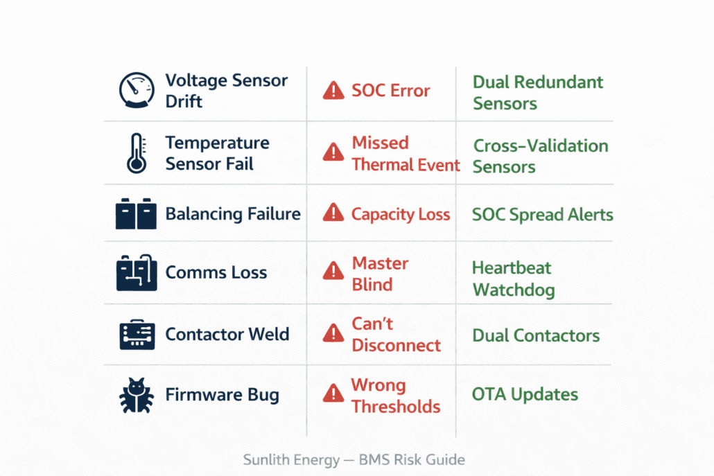
Common battery management system failure modes and how to prevent each one in a BESS installation
Understanding how a battery management system can fail helps you design systems with the right redundancy. It also helps you evaluate suppliers whose BMS architecture accounts for these risks.
Failure Mode
Consequence
Prevention
Voltage sensor drift
Incorrect SOC — risk of overcharge or over-discharge
Dual redundant sensors; periodic recalibration against known references
Temperature sensor failure
Missed thermal event — possible thermal runaway
Multiple sensors per module; cross-validation between sensors
Balancing circuit failure
Cell imbalance grows; usable capacity shrinks
Active monitoring of balancing currents; SOC spread alerts
Master-slave communication loss
Master loses visibility of module status
Slaves maintain local protection; heartbeat watchdog triggers alarm
Contactor weld failure
BMS cannot disconnect pack during a fault
Pre-charge circuits; contactor health monitoring; dual contactors on large systems
OTA firmware updates; staged rollouts; version logging with rollback capability
11. The Battery Management System in a Complete BESS: System Integration
Importantly, the battery management system does not operate in isolation. In a complete BESS, it sits at the centre of a data and control network — connecting cells to the inverter, the EMS, the monitoring platform, and the thermal management system.
Connecting to the Inverter
The BMS sends SOC, available power, voltage, and fault status to the inverter in real time. The inverter uses this data to manage charge and discharge rates and respect SOC limits. It also triggers a soft shutdown when the battery approaches empty.
Without reliable BMS-to-inverter communication, the inverter operates blind. As a result, overcharge or deep discharge events become possible.
Connecting to the Energy Management System (EMS)
The EMS sits above the BMS in the control hierarchy. It uses BMS data to decide when to charge, when to discharge, and how much power to commit to a grid services contract. Consequently, a BMS that cannot communicate reliably with the EMS limits the system’s ability to optimise for economics.
To understand how BESS economics work in practice, see our guide on calculating BESS ROI.
Connecting to Remote Monitoring Platforms
Cloud-connected monitoring platforms use BMS data to track performance and flag early warnings. Typical parameters include SOC, SOH, cell voltage spread, temperatures, energy throughput, and fault logs. Moreover, this data is increasingly required for EU Battery Passport compliance after 2027.
Connecting to Thermal Management Systems
In systems with active cooling — fans or liquid cooling — the BMS directly controls the thermal hardware. It turns cooling on and off based on real-time cell temperature readings. In liquid-cooled NMC systems, this link is especially critical. In LFP systems, thermal management is simpler — but still important in warm climates or poorly ventilated enclosures.
Conclusion: The Battery Management System Is Not a Commodity
The battery management system determines whether a BESS is safe. It also determines whether cells reach their rated cycle life — and whether capacity is fully used. It is, therefore, not a component to be cut from the bill of materials.
Here are the key takeaways from this guide:
Cell-level voltage and temperature monitoring are non-negotiable in any lithium system
SOC algorithm choice matters enormously — especially for LFP’s flat voltage curve
Balancing method should match your cycle frequency and system size
SOH logging is now a regulatory requirement under the EU Battery Passport — not just a technical feature
BMS architecture must scale with system size: single-level for residential, master-slave for commercial and utility
Use the eight evaluation questions above before accepting any supplier’s BMS specification
Overall, whether you are designing a 10 kWh home system or a 10 MWh grid-scale BESS, the battery management system deserves the same scrutiny as the cells. A good BMS extends the life of average cells. A poor BMS, in contrast, shortens the life of great ones.
☀️ Need a Battery Management System Review for Your BESS Project? Sunlith Energy reviews BMS specifications and supplier documentation for BESS projects from 50 kWh upward. Specifically, we identify gaps in protection architecture, SOC algorithm suitability, and certification compliance — before you sign a purchase order. Contact us
Frequently Asked Questions About the Battery Management System
Does a LiFePO4 battery need a BMS?
Yes — without exception. LiFePO4 is chemically stable, but it still needs a battery management system. Specifically, the BMS prevents overcharge, over-discharge, short circuit, and thermal damage. No reputable BESS supplier ships lithium cells without one.
What is the difference between a BMS and a battery controller?
The battery management system monitors and protects individual cells and modules. A battery controller — or Master BMS — manages the full system and coordinates with the inverter and EMS. In simple residential systems, one device does both. In large commercial systems, however, they are typically separate hardware.
Can a BMS extend battery life?
Yes — significantly. A BMS keeps cells within safe voltage and temperature limits. It also maintains good cell balance and enforces appropriate C-rate limits. As a result, it extends cell life considerably compared to unprotected operation.
This depends on your inverter and EMS. CAN bus is most common in high-performance systems. Modbus RTU over RS485, however, is standard in commercial and industrial storage. Check your inverter’s compatibility list first — mismatched protocols require additional gateway hardware and add cost and complexity.
How do I know if my BMS is failing?
Watch for these warning signs: SOC readings that jump unexpectedly; growing cell voltage spread, which indicates poor balancing; shutdowns not caused by actual low SOC; temperature readings that are static or incorrect; and fault codes that repeat in the log without a clear cause. In particular, growing cell voltage spread is often the earliest signal of BMS trouble.
Remote monitoring platforms are, therefore, the most reliable early detection tool. They flag SOC spread and temperature anomalies before they become failures.
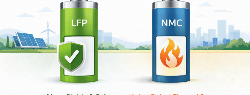
The NMC battery vs LFP safety gap starts with one number: LFP triggers thermal runaway at 270–300°C — NMC reaches it at just 150–210°C. That 150°C difference determines fire risk, toxic gas exposure, BMS complexity, and real installation cost for any BESS project.
This guide covers the full NMC battery vs LFP safety comparison. Specifically, we look at thermal runaway, fire risk, gas emissions, BMS needs, and real-world installation differences. By the end, you will know which chemistry is safer — and why.
Lithium-ion batteries store a lot of energy in a small space. So when something goes wrong, the results can be severe. However, not all chemistries fail the same way.
The cathode material is the key factor. It determines how much heat is released during failure. Fire spread speed also depends on the cathode. Therefore, picking the right chemistry is a safety decision — not just a performance one.
NMC Battery vs LFP Safety: Thermal Runaway Risk
#image_title
Thermal runaway is the main safety hazard in lithium-ion batteries. Specifically, it happens when a cell overheats and starts a chain reaction. As a result, the cell releases heat, gas, and possibly fire — faster than any cooling system can stop.
What causes thermal runaway?
Common causes include:
Overcharging — voltage pushed above the safe limit
External heat — high ambient temperature or nearby fire
Internal short circuit — from a defect or physical damage
Deep over-discharge — damages the anode structure
Mechanical abuse — crushing, puncture, or impact
Both LFP and NMC can suffer thermal runaway. However, the temperature at which it starts — and what happens next — is very different.
NMC battery vs LFP safety: thermal runaway temperature
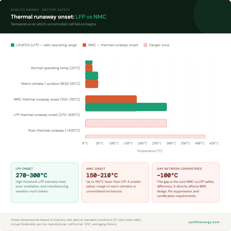
LFP cells begin thermal runaway at around 270°C–300°C. This is a high threshold. Because of this, LFP handles heat, poor ventilation, and temperature spikes much better.
NMC cells, on the other hand, begin thermal runaway at around 150°C–210°C. At up to 150°C lower than LFP, NMC reaches the danger zone much faster under the same conditions.
This gap matters a lot in practice. For example, a BESS in a warm climate or a poorly ventilated enclosure can easily reach 40°C–50°C. LFP handles that temperature comfortably. NMC, however, has a much smaller safety margin at that point.
✅ For outdoor BESS, rooftop solar, or any site without active cooling — LFP’s higher thermal runaway threshold is a critical safety advantage.
NMC Battery vs LFP Safety: Fire Risk and Propagation
#image_title
Even if one cell enters thermal runaway, a good system should stop it from spreading. However, chemistry determines how hard that containment is.
LFP fire risk
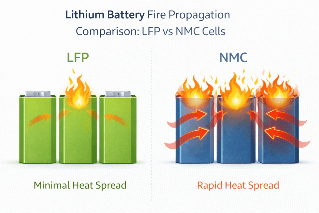
When an LFP cell fails, the reaction is relatively slow. In addition, the iron-phosphate cathode releases very little oxygen. As a result, fire spreading to nearby cells is much less likely — especially with proper spacing and thermal management.
LFP fires can still happen. Nevertheless, they are generally manageable with standard fire suppression systems. This includes systems required under NFPA 855 and UL 9540A.
NMC battery fire risk
NMC thermal runaway is more energetic. Notably, the cathode releases oxygen as it breaks down. That oxygen feeds the fire directly. As a result, NMC fires can spread to adjacent cells very fast. Experts call this thermal runaway cascade or cell-to-cell propagation.
NMC fires also burn hotter and produce more toxic smoke. Therefore, they need stronger fire suppression, more cell spacing, and better containment in module design.
This is exactly why UL 9540A testing exists. In short, it measures how far a fire can spread in a battery system. For more on certifications, see our guide to UL certifications for battery systems.
NMC Battery vs LFP Safety: Toxic Gas Emissions
#image_title
Battery failures produce dangerous gases. Importantly, the type and amount of gas depend on the chemistry.
LFP gas emissions
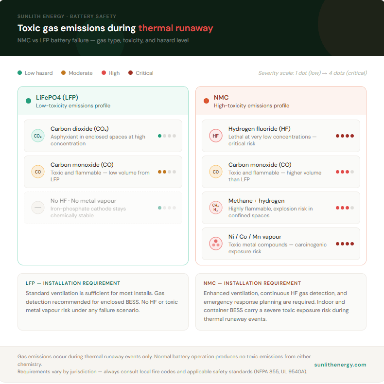
LFP cells mainly release carbon dioxide (CO₂) and small amounts of carbon monoxide (CO) during failure. Both are hazardous in enclosed spaces. However, LFP produces much lower volumes of toxic or flammable gas than NMC.
NMC battery gas emissions
NMC cells release a more dangerous mix of gases, including:
Hydrogen fluoride (HF) — highly toxic even at low levels
Carbon monoxide (CO) — toxic and flammable
Methane and hydrogen — highly flammable
Nickel and cobalt compounds — toxic metal vapours
Because of this, NMC failures in enclosed spaces carry a much higher toxic exposure risk. Container BESS, basement installs, and indoor commercial storage all fall into this category. Therefore, NMC systems need better ventilation and gas detection than LFP.
NMC Battery vs LFP Safety: BMS Requirements
A Battery Management System (BMS) is the main electronic protection against battery failure. However, NMC and LFP place very different demands on the BMS. For a full overview, see our BMS monitoring and protection guide.
LFP BMS needs
LFP has a flat charge-discharge voltage curve. Consequently, this makes State of Charge (SOC) harder to measure. However, the chemistry is stable. So the BMS has more time to catch a developing fault before it becomes dangerous.
Key BMS functions for LFP:
Cell balancing — important due to the flat voltage curve
Temperature monitoring — less critical than NMC, but still needed
Overcharge and over-discharge protection
NMC battery BMS needs
NMC is far more sensitive to voltage and temperature changes. Speed and precision matter more. As a result, the BMS must react faster and with tighter tolerances. In particular, NMC requires:
Tighter voltage windows — NMC is damaged more easily by overcharge or deep discharge
Continuous temperature monitoring — the low thermal runaway threshold means any heat spike is a risk
Faster fault response — the BMS must disconnect the system quickly
Cell-level monitoring — NMC cells age unevenly, so individual cell data matters
Therefore, NMC-based BESS systems need a more advanced BMS than LFP. Consequently, this adds cost, complexity, and more potential points of failure in the safety chain. The BMS is just one piece — but it is the one that ties all the others together.
NMC Battery vs LFP Safety: Certification Standards
Safety certifications test how battery systems behave under fault conditions. Because NMC and LFP behave so differently, the effort required to pass differs too.
Key standards for NMC battery vs LFP safety
Standard
What it covers
Key note
UL 9540
Complete BESS system safety
Both chemistries must comply for US market
UL 9540A
Fire propagation testing
Harder to pass for NMC
UL 1973
Stationary battery safety
Cell and module level
IEC 62619
Lithium-ion battery safety
International standard for both
NFPA 855
Fire code for energy storage
Stricter spacing often needed for NMC
IEC 62933-5
ESS safety framework
Applies to both
Why NMC faces a harder certification path
UL 9540A tests fire propagation. Specifically, it checks whether a thermal runaway event in one cell can spread to the rest of the system. Oxygen is released by NMC during failure. Because of this, fire propagation is more likely. As a result, systems using NMC often need more cell spacing, stronger thermal barriers, and better fire suppression to pass.
NFPA 855 also applies stricter spacing rules to higher-hazard systems. In practice, this means NMC BESS may need more floor area and more separation from occupied spaces. For a full overview, see our guide to IEC 62933-5 safety standards.
NMC Battery vs LFP Safety: Real-World Installation Differences
The NMC battery vs LFP safety difference is not just theory. It shows up in real project decisions every day.
Outdoor and warm-climate BESS
LFP is strongly preferred for outdoor BESS and warm-climate deployments. In particular, its high thermal runaway threshold means it handles heat without the active cooling NMC needs.
NMC in warm or outdoor settings, on the other hand, needs robust thermal management. Active liquid cooling or high-capacity HVAC is usually required. Therefore, the safety system becomes more complex and more expensive.
Indoor and occupied-building storage
NMC’s higher gas toxicity and fire spread risk make it harder to use near occupied spaces. In contrast, LFP’s lower emissions and slower failure mode make it a better fit for behind-the-meter C&I storage in commercial buildings.
Moreover, insurers and building inspectors are increasingly aware of the chemistry difference. As a result, LFP installations often get through planning and permitting faster than NMC.
Container-based utility-scale BESS
For large container BESS, both chemistries are used. However, NMC containers need more fire suppression, more cell spacing, and more thermal management. As a result, LFP containers can be packed more efficiently and at lower cost — while still meeting the same safety standards.
NMC Battery vs LFP Safety: Head-to-Head Summary
Safety factor
LFP
NMC
Thermal runaway threshold
~270–300°C
~150–210°C
Oxygen release during failure
Very low
High
Fire propagation risk
Low
High
Toxic gas emissions
Low (CO, CO₂)
High (HF, CO, metal vapour)
BMS complexity needed
Standard
High
UL 9540A difficulty
Lower
Higher
NFPA 855 spacing
Standard
Often stricter
Outdoor BESS suitability
Excellent
Moderate — needs active cooling
Indoor / occupied-space use
Good
Needs extra mitigation
Overall BESS safety risk
Lower
Higher
Which Is Safer? The NMC Battery vs LFP Safety Verdict
For stationary energy storage — BESS, solar storage, C&I, utility-scale — LFP is the safer choice. Its higher thermal runaway threshold makes it more tolerant of heat. Lower fire spread risk and reduced toxic emissions add to that advantage. Overall, every key safety dimension favours LFP.
NMC is not unsafe when it is designed and installed correctly. However, it needs more thermal management, a more advanced BMS, stronger fire suppression, and stricter installation controls to reach the same safety level as LFP. As a result, the cost of making NMC safe for stationary storage is higher.
Most utility-scale and C&I BESS projects globally now specify LFP for exactly this reason. Indeed, the safety profile — combined with longer cycle life and lower lifetime cost — makes LFP the dominant choice for stationary storage.
Frequently Asked Questions
Is NMC battery vs LFP safety a big difference in practice?
Yes. The gap is significant. A thermal runaway threshold up to 150°C lower than LFP is a major difference. More oxygen, more toxic gas, and faster fire spread come with it. Therefore, NMC needs more safety infrastructure to reach the same risk level as LFP.
Is NMC dangerous for BESS?
Not inherently — when properly designed, certified, and installed, NMC is manageable. However, the lower thermal runaway threshold and higher fire risk compared to LFP mean more work is required. As a result, more sophisticated thermal management and fire suppression are needed.
Why does LFP have a higher thermal runaway threshold than NMC?
The iron-phosphate bond in LFP is chemically more stable than the nickel-cobalt-manganese structure in NMC. Consequently, LFP needs much more heat to trigger decomposition and thermal runaway.
Can NMC pass UL 9540A?
Yes. Many NMC systems have passed UL 9540A. However, passing often requires more cell spacing, thermal barriers, and fire suppression than LFP needs. As a result, NMC certification takes more effort and cost.
Is LFP safe for indoor BESS installations?
Absolutely. LFP’s lower fire spread risk and reduced toxic gas profile make it more suitable than NMC for indoor and occupied-building installs. However, all BESS installations must still comply with local fire codes and applicable standards.
What happens if a single NMC cell fails in a large BESS?
In a well-designed NMC system, a single cell failure should be contained by the BMS, thermal management, and module-level barriers. However, because NMC releases oxygen during thermal runaway, fire can spread to adjacent cells if containment is not strong enough. Specifically, this is what UL 9540A testing is designed to evaluate.
Final Thoughts
The NMC battery vs LFP safety comparison has a clear result for stationary storage. Overall, LFP wins on thermal runaway threshold, fire propagation, toxic gas emissions, and BMS simplicity. As a result, it is the safer and more practical choice for BESS, solar storage, and C&I projects.
NMC works well where energy density is the top priority and where the extra safety infrastructure can be justified. However, for most stationary storage projects, LFP is the lower-risk option — in safety terms and in cost terms.
One final rule: always evaluate safety at the system level. Chemistry is just one piece. The BMS, thermal management, fire suppression, and installation conditions all matter equally. Therefore, always check that your supplier’s certification covers the full installed system — not just individual cells.
UL 2054 certification is the core safety standard for complete battery packs sold in North America. Underwriters Laboratories publishes it. A cell-level standard tests one component. UL 2054, on the other hand, tests the finished pack as a whole — the housing, the wiring, and the protection circuits, all working together.
This guide covers what actually sets UL 2054 apart. First, you’ll see the Single Fault Condition test. Next, you’ll learn the two paths to certification. Then, we’ll explain why the cells inside your pack need their own approval first. For the cell-level standard this builds on, see our UL 1642 certification guide. Or, browse our full UL certifications overview for the complete compliance picture. The U.S. Consumer Product Safety Commission also lists UL 2054 as a recognized voluntary standard for household and commercial batteries.
What UL 2054 Covers — and What It Doesn’t
UL 2054 applies to complete battery packs. This includes both primary, non-rechargeable batteries and secondary, rechargeable ones. It covers several chemistries too: lithium-ion, lithium-polymer, NiMH, and NiCd.
However, the standard doesn’t test individual cells on its own. Instead, it points to UL 1642 for the lithium cells used inside a pack. In practice, this means the cells need UL 1642 approval first, before the finished pack goes to a lab for UL 2054 testing. Skipping this step doesn’t skip the requirement. It just shifts the burden. If a pack arrives with uncertified cells, the lab has to run the full UL 1642 cell tests too. As a result, this roughly doubles both the testing cycle and the cost.
UL 2054 also stops at a certain scale. It doesn’t cover electric vehicle batteries, since those fall under UL 2580. It doesn’t cover industrial or stationary storage batteries either, since those fall under UL 1973. Think of UL 2054 as the standard for everything in between: the packs inside laptops, power tools, e-bikes, medical devices, and household energy storage products.
The Testing Categories
UL 2054 groups its requirements into four areas. Each one targets a different way a pack can fail.
Electrical — short-circuit testing at multiple temperatures, an abnormal charging test, an abusive overcharge test at an elevated charge rate, a forced-discharge test for multi-cell configurations, and a Limited Power Source (LPS) test.
Mechanical — a crush test using a hydraulic ram, an impact test with a drop weight, shock testing, and vibration testing that simulates shipping and handling.
Environmental — temperature cycling, humidity exposure, and low-pressure altitude simulation.
Enclosure — a mold stress test, a drop test, and a static force test on the housing itself. After all, the casing is the pack’s first line of defense if something goes wrong internally.
Across every category, the underlying requirement stays the same: no fire, and no explosion. For pack-level samples specifically, the pack also can’t leak electrolyte through a cracked or ruptured cell casing. For a broader look at how labs approach battery testing generally, UL’s own battery safety testing overview is a useful reference.
The Single Fault Condition Test
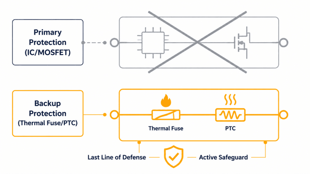
This is the detail that most separates UL2054 from a simpler pack test. Yet it rarely gets explained clearly. Most battery packs ship with two layers of protection: a primary IC-based circuit, and a secondary fuse or protection device.
During testing, the lab doesn’t just check that both layers work. Instead, it deliberately disables one. Typically, this means intentionally shorting the primary protection MOSFET or IC, to simulate a real-world failure of that first layer. The pack then has to survive on its remaining protection alone — commonly a thermal fuse or PTC device — during an overcharge event. A pack that depends entirely on its primary IC, with no independent hardware backup, tends to fail here. In fact, this is the most common reason a first submission doesn’t pass.
Two Paths to UL 2054 Certification
Manufacturers can pursue UL 2054 compliance in two different ways. The right choice depends on where the product is sold.
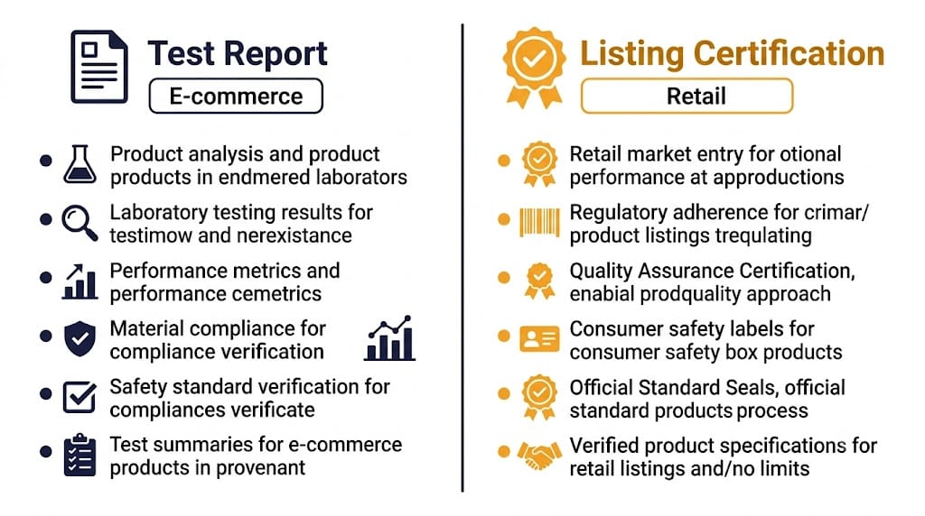
UL 2054 Test Report
UL 2054 Listing Certification
What it includes
Lab testing only, no factory audit
Lab testing plus ongoing quarterly factory inspections
Speed and cost
Faster and lower cost
Slower and more expensive, due to the audit program
Allows the UL Mark?
No
Yes
Typical use case
E-commerce platforms like Amazon
Offline retail and big-box distribution
Amazon specifically requires a UL 2054 test report from an ISO 17025-accredited lab for lithium battery listings. If a listing gets flagged for missing documentation, sellers typically get a narrow window — often 14 to 30 days — to submit a valid report. Otherwise, the listing faces removal. For manufacturers targeting physical retail instead, the full Listing Certification with the UL Mark is usually the better long-term investment. Many retail buyers specifically require it.
How UL 2054 Fits With Other UL Battery Standards
UL 2054, UL 1642, UL 1973, UL 2580, and UL 9540 get confused constantly. That’s because they all show up in battery compliance conversations. However, each one certifies a different scope.
Standard
What It Covers
UL 1642
Individual lithium-ion or lithium-metal cells
UL 2054
Complete battery packs for consumer and commercial products
UL 1973
Batteries for stationary storage (BESS), light electric rail, and similar applications
UL 2580
Battery packs and modules used in electric vehicles
UL 9540
The complete energy storage system — batteries, PCS, controls, and enclosure together
In short, UL 2054 sits between cell-level and system-level safety. It confirms the pack itself is safe, before that pack goes into a larger product or system. For the standard that governs full BESS installations, see our UL 9540A test method guide.
Why UL 2054 Certification Matters
Market access — most major retailers and e-commerce platforms require it before listing a lithium battery product.
Liability protection — a UL 2054 report demonstrates due diligence if a product safety issue is ever challenged.
Foundation for trust — for household energy storage products specifically, pack-level certification reassures buyers that the same rigor applies as it does to larger BESS installations.
At Sunlith Energy, every battery pack we source starts with UL 1642-certified cells before pack-level testing begins. See our BESS certifications overview for a buyer’s-side breakdown of what to verify before purchasing.
Frequently Asked Questions
Does UL 2054 test individual battery cells?
No. UL 2054 tests the complete pack — housing, wiring, and protection circuits. It references UL 1642 for the lithium cells inside the pack. So, those cells need separate UL 1642 approval first.
What is the Single Fault Condition test?
It’s a test where the lab intentionally disables one layer of a pack’s protection circuit. Then, it checks whether the remaining protection can still prevent fire or explosion during an overcharge event. This is one of the most common reasons a first test submission fails.
What’s the difference between a UL 2054 Test Report and Listing Certification?
A Test Report covers lab testing only. It’s typically enough for e-commerce platforms like Amazon. Listing Certification adds ongoing factory audits and allows use of the UL Mark, which offline retail distribution usually requires.
Does UL 2054 cover EV or stationary storage batteries?
No. EV battery packs fall under UL 2580. Stationary storage batteries fall under UL 1973 instead. UL 2054 covers the range in between: consumer and commercial products like power tools, e-bikes, medical devices, and household energy storage.
UL 1642 certification is the core U.S. safety standard for lithium-ion and lithium-metal cells. Underwriters Laboratories publishes this standard. Most cell manufacturers need UL 1642 certification before selling into the North American market. This certification tests the cell itself. It happens before the cell ever becomes part of a battery pack or energy storage system.
This guide explains what UL 1642 actually requires. First, you’ll see the scope and gram limits that define which cells qualify. Next, you’ll learn the four categories of abuse testing. Then, we’ll cover a realistic certification timeline. Finally, we’ll compare UL 1642 to UN 38.3 and IEC 62133. For system-level certifications that come after cell approval, see our UL 1973 certification guide and our full UL certifications overview.
UL 1642 Certification Scope: Which Cells Qualify?
UL 1642 certification applies to lithium-ion and lithium-metal cells. It does not cover complete battery packs, modules, or energy storage systems. This distinction matters, because it determines which certification you actually need.
For user-replaceable applications, the standard sets clear limits. A battery must contain no more than 4.0g of total lithium content. No single cell may exceed 1.0g of metallic lithium. Cells above these limits need additional evaluation. Once a cell earns UL 1642 certification, it becomes the foundation for pack-level certifications. Most manufacturers pursue UL 2054 next for household and commercial packs. Others pursue UL 1973 for stationary and BESS applications.
UL 1642 Certification: The Four Testing Categories
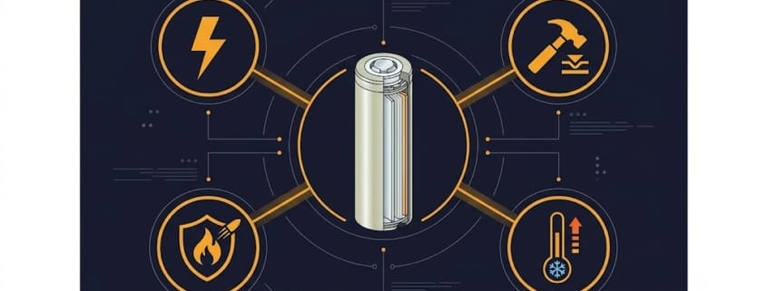
UL 1642 certification evaluates cells across four testing categories. Each one simulates a real-world failure mode.
Electrical — the lab runs a short-circuit test, an overcharge test, and a forced discharge test.
Mechanical — technicians perform a crush test, an impact test, a shock test, and a vibration test.
Environmental — testers apply a heating test, temperature cycling, and a low-pressure altitude test.
Projectile — this test confirms a failed cell can’t become a projectile that penetrates a surrounding mesh screen.
Together, these tests confirm the cell resists fire, explosion, and leakage. As a result, UL 1642 certification becomes a prerequisite for nearly every downstream battery certification.
How Long Does UL 1642 Certification Take?
The UL 1642 certification process starts with sample submission. Manufacturers typically submit both fresh and pre-aged cells. This approach evaluates performance across the cell’s expected life, not just out of the box. From there, the lab runs the full test suite: electrical, mechanical, environmental, and projectile tests.
Most manufacturers should plan for roughly 8–12 weeks from sample submission to certificate issuance, though lab capacity and sample variants affect the schedule. You can verify any UL certificate directly through UL’s Product iQ database.
UL 1642 vs UN 38.3: Two Different Kinds of Safety
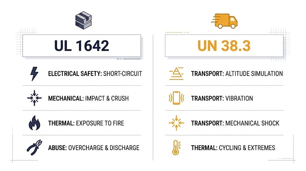
People often confuse UL 1642 with UN 38.3. However, these standards test completely different risks. UL 1642 certification proves product-use safety — it confirms a cell resists short circuits, overcharge, and crush damage. UN 38.3 proves transport safety instead — it confirms a cell survives shipping conditions like altitude changes, vibration, and shock.
Every international lithium battery shipment legally requires UN 38.3 testing. Meanwhile, manufacturers need UL 1642 certification for U.S. market access. In short, most manufacturers need both. Neither certification replaces the other.
UL 1642 Certification
UN 38.3
What it certifies
Product-use safety
Transport / shipping safety
Core tests
Short circuit, overcharge, crush, abnormal charging
Altitude simulation, thermal cycling, vibration, shock, external short circuit
Who requires it
OEMs, retailers, and North American market access
Legally required for every international lithium battery shipment
Can one replace the other?
No — both are typically required
No — both are typically required
In practice, a cell manufacturer shipping internationally needs both certifications: UN 38.3 to legally move the product, and UL 1642 certification to sell it into the U.S. market.
UL 1642 vs IEC 62133
IEC 62133 is the closest international equivalent to UL 1642. Companies selling into the EU or Asia usually need IEC 62133 instead. Both standards test similar risks. However, they aren’t interchangeable. IEC 62133 generally covers portable sealed cells across a broader range of chemistries. UL 1642 certification, on the other hand, applies specifically to lithium-ion and lithium-metal cells. Additionally, OSHA-recognized labs in the U.S. reference UL 1642 certification directly. For this reason, manufacturers targeting multiple markets typically pursue both.
UL 1642 Certification in Context: UL 1973 and UL 9540
UL 1642, UL 1973, and UL 9540 often get confused in BESS compliance conversations. However, each standard certifies a different layer of the system.
Standard
What It Covers
UL 1642
Individual lithium-ion or lithium-metal cells
UL 1973
Complete battery modules and packs for stationary storage, EVs, and light rail
UL 9540
The full energy storage system — batteries, PCS, controls, and enclosure together
A cell typically earns UL 1642 certification before a manufacturer can integrate it into a UL 1973-certified pack. That pack, in turn, supports UL 9540 certification for the complete system. For the pack-level standard specifically, see our UL 2054 certification guide.
Why UL 1642 Certification Matters
Market access — most North American retailers require UL 1642 before they’ll sell a product.
Foundation for downstream certification — UL 2054 and UL 1973 both require cells that already carry UL 1642 certification.
Liability protection — manufacturers commonly use UL 1642 certification reports as evidence of due diligence.
UL 1642 covers individual lithium-ion and lithium-metal cells. It does not cover complete battery packs. Pack-level safety falls under separate standards, like UL 2054 or UL 1973.
W
How long does UL 1642 certification take?
Most manufacturers should plan for 8–12 weeks, from sample submission to certificate issuance. Lab capacity and sample variants can affect the schedule.
How is UL 1642 certification different from UN 38.3?
UL 1642 certification tests product-use safety. UN 38.3 tests transport safety instead. Most manufacturers need both.
Is UL 1642 mandatory for all lithium-ion cells?
UL 1642 is not a legal requirement by itself, but is effectively mandatory for most North American OEMs, retailers, and import channels, and is treated as a baseline by NRTL labs and many corporate safety policies.
Can a pack be UL 2054 or UL 1973 certified if its cells are not UL 1642 certified?
No, a battery pack cannot be UL 2054 or UL 1973 certified unless its constituent cells are UL 1642 certified. Both of these pack-level standards mandate that the internal cells meet the basic cell-level safety standards of UL
What happens if we change cell chemistry after UL 1642 certification?
Changes to chemistry, materials, or manufacturing process must be reported to the lab, can trigger partial re‑testing, and that failing to report changes is a common cause of certification invalidation.
Does UL 1642 cover both lithium-ion and lithium-metal cells?
Yes, it covers both, but still only at the cell level. Battery packs and modules require additional certifications such as UL 1973 for stationary applications and UL 9540 for full energy storage systems.
UL 2271 Certification: A Safety Standard for Modern Mobility
The popularity of light electric vehicles (LEVs) such as e-bikes and scooters has surged in cities worldwide. With this growth comes an urgent need for reliable and safe batteries. UL 2271 certification provides a trusted benchmark, ensuring lithium-ion batteries used in LEVs are tested for safety, reliability, and durability.
At Sunlith Energy, we understand that safety is not optional—it is the foundation of innovation in clean mobility. That is why UL 2271 plays a vital role in our approach to powering the next generation of transport solutions.
What is UL 2271?
UL 2271 is a standard developed by UL Solutions, titled “Batteries for Use in Light Electric Vehicle Applications.” It applies to rechargeable lithium-ion batteries and battery packs designed for vehicles like:
Electric bicycles (e-bikes)
Electric scooters
Utility carts and campus shuttles
Personal mobility devices
This certification addresses risks such as fire, thermal runaway, and electrical failure, giving users peace of mind while adopting electric transport.
Why UL 2271 Matters for LEVs
Lithium-ion batteries can fail under stress or misuse, sometimes causing dangerous incidents. UL 2271 reduces these risks through rigorous testing and quality checks. The benefits extend across the ecosystem:
For Consumers – Safer rides with fewer risks of overheating or fires.
For Manufacturers – Compliance that strengthens brand trust and accelerates market approval.
For Regulators – A standardized approach to evaluating battery safety. Agencies such as the U.S. Consumer Product Safety Commission (CPSC) reference UL certifications when assessing risks.
For Fleet Operators – Fewer breakdowns, lower insurance risks, and higher uptime.
By aligning with UL 2271, manufacturers demonstrate a commitment to safety and long-term reliability.
Core Testing Areas in UL 2271
The certification process is extensive, covering every aspect of battery behavior:
Electrical Performance
Overcharge and discharge protection
Short-circuit resistance
Abnormal charging safety
Mechanical Safety
Crush resistance
Drop impact testing
Vibration endurance
Environmental Conditions
Temperature cycling (hot and cold)
Humidity and corrosion exposure
Thermal stability
Abuse Scenarios
Nail penetration
Fire exposure
Forced discharge tests
These simulations ensure that batteries are safe not only under normal use but also in extreme and unexpected conditions.
Where UL 2271 Certified Batteries Are Used
Certified batteries can be found across a variety of mobility applications:
Micromobility fleets – Shared e-scooters and bikes in urban environments
Logistics and delivery – Small electric utility vehicles for last-mile transport
Campus and industrial transport – Electric carts in universities, resorts, and warehouses
Personal recreation – Electric skateboards, hoverboards, and other small vehicles
As cities embrace greener mobility, UL 2271 ensures these devices meet the highest standards of safety.
How UL 2271 Compares to Other Standards
Different UL standards apply to batteries depending on their use case. Here’s how UL 2271 fits into the bigger picture:
This distinction makes UL 2271 the go-to certification for smaller mobility solutions, bridging the gap between consumer electronics and large electric vehicles.
Benefits for Manufacturers
For companies producing batteries and light mobility systems, UL 2271 certification unlocks significant advantages:
Global Market Access – Many import and sales channels require UL approval.
Consumer Trust – Certified products carry the UL mark, a symbol of safety.
Fewer Recalls – Certified designs lower the risk of costly failures.
Brand Differentiation – Compliance shows leadership in product responsibility.
At Sunlith Energy, we believe certification is not only about meeting regulations but also about earning customer confidence.
Global Adoption of UL 2271
Though it originates in the United States, UL2271 is recognized worldwide. European markets, as well as regions in Asia-Pacific, increasingly request UL-certified products. Organizations like the European Committee for Electrotechnical Standardization (CENELEC) often align their safety requirements with UL or IEC standards such as IEC 62133.
Challenges in Certification
Adopting UL 2271 isn’t without hurdles:
Testing and approval costs can be high.
Certification takes time, which may affect product launches.
Standards evolve as technology advances, requiring ongoing compliance updates.
However, for manufacturers committed to long-term success, the benefits outweigh the costs.
The Future of UL 2271
As micromobility grows, the importance of UL2271 will only increase. We expect:
Tighter adoption by regulators and fleet operators.
Integration with international standards like IEC 62133.
Adjustments for new technologies such as semi-solid and solid-state batteries.
UL2271 will remain a critical part of ensuring that e-mobility remains safe, sustainable, and trusted.
Conclusion
UL 2271 certification is more than a technical requirement—it is a safety guarantee. For consumers, it provides assurance that their rides are reliable. For manufacturers, it opens global markets and builds trust. For regulators, it creates consistency.
At Sunlith Energy, we see UL2271 as a cornerstone in shaping a secure, innovative, and eco-friendly mobility future. Learn more about our work in certification and compliance by exploring global battery certifications.
FAQs
Q1: Does UL 2271 apply to large EVs like cars?
No. Large EVs fall under UL 2580. UL2271 is specifically designed for smaller vehicles such as scooters and e-bikes.
Q2: Is certification mandatory?
While not always legally required, many retailers, regulators, and fleet programs demand UL compliance before accepting products.
Q3: How long does certification take?
Timelines vary, but manufacturers should prepare for several weeks to months depending on design complexity.
Q4: Does UL 2271 cover battery management systems (BMS)?
Yes. The standard includes evaluations of cells, packs, and electronic control systems.
Q5: Can UL 2271 certified batteries be used in storage systems?
No. Stationary energy storage solutions fall under UL 9540/9540A.
The UL 9540A Test Method is the only national standard that measures how thermal runaway fire spreads inside a battery energy storage system. It covers everything from a single cell all the way to a full real-world installation.
Most U.S. states require this test. Both NFPA 855 and the International Fire Code reference it directly. Without UL 9540A test data, large BESS projects simply cannot receive AHJ approval.
This guide covers everything you need:
What UL 9540A tests and why it matters
All 4 test levels with pass/fail criteria
Real costs, timelines, and lab selection tips
Every change in the 2025 Fifth Edition
How UL 9540A connects to UL 9540 certification
Who needs it and exactly when
What is the UL 9540A Test Method?
The UL 9540A Test Method — formally titled “Standard for Evaluating Thermal Runaway Fire Propagation in Battery Energy Storage Systems” — measures specifically how a battery fire behaves once it starts.
Most safety certifications cover general equipment performance. This standard, however, focuses purely on fire propagation. In other words, it answers one critical question: will a failure in one cell, module, or unit spread to the rest of the system?
That narrow focus makes it the go-to reference for engineers, installers, and Authorities Having Jurisdiction (AHJs) across the United States. According to UL Solutions, the standard is widely adopted because it provides reproducible, science-based data that fire authorities can consistently apply across different projects and jurisdictions.
The standard answers three specific safety questions:
Cell propagation — whether thermal runaway in a single cell spreads to adjacent cells or the full module
Fire behaviour — how a battery module or full ESS unit reacts during a fire, including flame height, gas release, and heat output
Suppression effectiveness — whether built-in or external fire suppression systems can prevent explosion, deflagration, or reignition
No other national standard addresses all three at once.
BESS installations — whether residential, commercial, or utility-scale — fall under NFPA 855 and the International Fire Code in most U.S. states. Both codes reference the UL 9540A Test Method directly as the required fire safety test for stationary energy storage systems. Moreover, the National Fire Protection Association updates NFPA 855 regularly to reflect new battery technologies and installation environments. For a deeper dive into these installation standards, see our Complete Guide to NFPA 855.
This standard ensures three important things for the industry:
Manufacturers can prove their systems are safe using science-based, reproducible test data
Installers receive clear installation parameters — separation distances, suppression specifications, and ventilation requirements — all derived directly from test results
Authorities Having Jurisdiction gain a reliable, nationally recognised safety benchmark for permit reviews
Without UL 9540A test data, a BESS product cannot be permitted in most U.S. commercial, industrial, or utility-scale projects. Therefore, it is not simply a competitive advantage — it is the entry ticket to the market.
UL 9540A four-level test hierarchy cell module unit and installation level
The UL 9540A Test Method uses a hierarchical four-level structure. Testing stops at the earliest level where no fire propagation is detected. As a result, not every product needs all four levels. This can significantly reduce cost and time for manufacturers whose chemistry performs well at cell or module level.
Level 1: Cell-Level Testing
Cell-level testing is where every UL 9540A program begins. A heater strip or nail penetration forces thermal runaway in a single cell while sensors record what happens next.
What gets measured:
Gas volume and composition, including hydrogen, CO, and CO₂
Peak heat release rate in kilowatts and total heat energy
Flame height, duration, and whether flames self-extinguish
Surface temperature of adjacent cells
Whether neighbouring cells ignite
Pass condition: Adjacent cells do not reach thermal runaway. When no propagation is detected, the test program stops here. Consequently, the manufacturer receives cell-level data and can move toward UL 9540 certification without module or unit testing.
What triggers escalation: If heat or gas from the first cell causes a second cell to enter thermal runaway, testing moves to Level 2.
Chemistry guidance: Most modern LiFePO₄ (LFP) cells pass at this stage because of their inherently stable chemistry and lower heat release. NMC and NCA chemistries, on the other hand, release significantly more heat and gas. Therefore, they are more likely to escalate to Level 2.
When cell-level testing shows propagation risk, the UL 9540A program moves to the module — a group of cells assembled exactly as they appear in a real BESS product. The same thermal runaway trigger applies to a single cell inside the fully assembled module.
What gets measured:
Whether thermal runaway spreads from the triggered cell to all other cells
Gas volume and composition vented from the full module
Flame spread across the module casing
Peak and sustained temperature of the module exterior
Whether the module casing ignites or deforms
Pass condition: Thermal runaway does not spread beyond the module boundary. Furthermore, the casing contains the event without external flaming or structural failure. When this condition is met, the manufacturer holds module-level data and can define safe installation spacing without moving to unit-level testing.
What triggers escalation: Flames, heat, or gas that could ignite an adjacent module in a real installation will push testing to Level 3.
Design insight: Module-level testing frequently reveals weaknesses in cell spacing, busbar design, and casing vent placement. For this reason, many manufacturers make design changes after Level 2 results before spending money on unit and installation tests.
At Level 3, the complete battery system — exactly as it would ship to a customer — undergoes testing. This includes battery modules, BMS, thermal management components, enclosure, and all internal wiring. Importantly, suppression systems are typically disabled at this level unless they are permanently integrated and cannot be removed.
What gets measured:
Whether thermal runaway spreads from the triggered module to other modules
Total gas volume vented from the enclosure
Explosion and deflagration risk from accumulated vented gases
Flame spread across the enclosure exterior
Peak temperatures on all external surfaces
Structural integrity of the enclosure after the event
Pass condition: No sustained external flaming occurs. Additionally, there is no detonation or deflagration of vented gases, and the enclosure does not fail in a way that exposes people or adjacent equipment to flames or hot gas.
What triggers escalation: If the unit vents enough flammable gas to create an explosion risk, or if external surfaces reach temperatures that could ignite surrounding materials, testing proceeds to Level 4.
Why AHJs focus here: Most Authorities Having Jurisdiction review unit-level data first when evaluating a BESS permit. The unit-level report defines minimum separation distances, ventilation requirements, and suppression specifications — all of which feed directly into the installation design.
Level 4 is the most comprehensive stage of the UL 9540A Test Method. Here, the system undergoes testing exactly as it would be installed — including active fire suppression, ventilation systems, and surrounding structural elements like walls and floors. Unlike Level 3, suppression systems are fully enabled.
What gets measured:
Whether active suppression successfully controls the fire event
Explosion and deflagration of vented gases in the confined installation space
Flame spread to surrounding structural elements
Reignition within 24 hours after suppression
Gas concentration levels during and after the event
Structural integrity of the installation environment post-event
Pass condition: No detonation or deflagration occurs. The suppression system controls the event. No sustained flaming spreads to surrounding structures. Furthermore, no reignition appears during the 24-hour post-test monitoring window.
What a pass unlocks: Installation-level data is the gold standard for AHJ approvals at commercial and utility scale. In addition, it defines the exact suppression system specification — type, activation threshold, and flow rate — that must be replicated in every real-world installation.
The UL 9540A Test Method uses four sequential levels. Cell-level testing checks whether a single cell’s thermal runaway spreads. Module-level testing then examines propagation across a full battery module. Next, unit-level testing evaluates the complete ESS with suppression disabled. Finally, installation-level testing runs the complete real-world scenario with suppression fully active. Because testing stops at the earliest clean level, many manufacturers never need to reach Level 4.
UL 9540A Pass/Fail Criteria: What Does the Test Actually Measure?
A BESS system passes the UL 9540A Test Method when all of the following conditions are met during and after the induced thermal runaway event:
Criteria
Pass Condition
Fire propagation
No spread beyond the unit boundary
Detonation / deflagration
Not observed at any point
Sustained flaming
Ceases within the post-test observation window
Suppression effectiveness
Active system controls the event
Reignition
None observed 24 hours post-test
What happens on a failure? A single failed criterion requires a design modification and re-testing from that specific level — not from the beginning. Most manufacturers use the results to improve cell spacing, separator design, or suppression placement before committing to the more expensive installation-level test.
UL 9540A Test Method Costs, Timelines, and Accredited Labs
One of the first questions manufacturers ask about the UL 9540A Test Method is simple: how much does it cost and how long will it take?
Test Level
Typical Duration
Estimated Cost (USD)
Cell level
2–4 weeks
$8,000–$20,000
Module level
3–6 weeks
$15,000–$40,000
Unit level
4–8 weeks
$25,000–$60,000
Installation level
6–12 weeks
$40,000–$100,000+
Full 4-level program
3–6 months
$80,000–$200,000+
Costs vary based on system size, chemistry, and lab availability. Retesting adds time and cost at the specific level that failed.
How to Choose a UL 9540A Accredited Test Lab
Not every lab can run all four test levels. Before booking, verify these four things:
IAS or A2LA accreditation specifically covering UL 9540A scope
Physical capacity for your unit or installation test size
Experience with your battery chemistry — LFP, NMC, or sodium-ion
Hydrogen detection capability, which the Fifth Edition now requires for relevant chemistries
Well-known accredited labs include UL Solutions, Intertek, TÜV SÜD, and SGS. Importantly, the best labs book out 3–6 months in advance. Start conversations before you are ready to test, not after.
UL 9540A vs UL 9540 vs UL 9540B: Key Differences
These three standards are closely related, yet they serve very different purposes. Confusing them is one of the most common and expensive mistakes in BESS certification.
Standard
Type
Scope
Who It Applies To
UL 9540
Certification
Full ESS system safety
Manufacturers seeking UL listing
UL 9540A
Test Method
Thermal runaway fire propagation
Anyone needing AHJ / NFPA 855 compliance
UL 9540B
Test Method
Residential vent gas ignition
Home BESS installers
The critical distinction: The UL 9540A Test Method produces a test report, not a certificate. That report feeds into UL 9540 certification and satisfies NFPA 855 and IFC requirements. In practice, you can hold UL 9540A data without being UL 9540 certified. However, you cannot achieve UL 9540 certification without it.
Together, these three standards form a complete safety framework — covering fire propagation at every scale from a single residential battery to a 100 MWh grid-scale installation.
Fifth Edition (2025): What Changed and What It Means for You
UL Solutions released the UL 9540A Test Method Fifth Edition on March 12, 2025. This update is the most significant revision since the standard’s introduction. Three forces drove the changes: rapid adoption of new battery chemistries, a surge in rooftop and residential BESS deployments, and real-world fire incidents that exposed gaps in the previous edition.
Below is every major change — and specifically what each one means in practice.
Change 1: Hydrogen Detection Protocols Now Explicitly Addressed
What changed: The Fifth Edition formally adds hydrogen sensor protocols to the test setup. Previously, hydrogen monitoring was optional and inconsistently applied across different labs.
What it means for you: If your BESS uses any chemistry that off-gasses hydrogen during thermal runaway — including lead-acid, certain NMC variants, and some older lithium chemistries — your chosen lab must now have hydrogen-rated enclosures and calibrated sensors. However, not all accredited labs have upgraded their facilities yet.
Action required: Before booking, specifically ask: “Are you equipped for hydrogen detection under the UL 9540A Fifth Edition?” Discovering this gap after scheduling typically adds several weeks to your timeline.
Change 2: Rooftop and Open Garage Installations Have Dedicated Criteria
What changed: The Fifth Edition adds specific test scenarios and pass/fail criteria for rooftop-mounted BESS and open garage installations — two of the fastest-growing deployment environments in commercial solar-plus-storage.
What it means for you: Before this update, AHJs evaluating rooftop BESS had to interpret indoor criteria and apply them to rooftop conditions, which led to inconsistent approvals. Now, if your product targets commercial rooftop projects, your UL 9540A test report must explicitly cover the rooftop installation scenario. A report based only on indoor unit-level testing will therefore not satisfy AHJ requirements for rooftop deployments.
Action required: Tell your test lab upfront that you need rooftop installation scenario data in the final report. This change affects test setup, not just documentation.
Change 3: Rest Times After Conditioning and Charging Are Clarified
What changed: The Fifth Edition specifies exact rest periods between cell conditioning, charging, and the thermal runaway trigger. Previously, labs interpreted these intervals differently, which produced inconsistent results across facilities.
What it means for you: Standardised rest times make results more reproducible and comparable across labs. If you have older UL 9540A data from before March 2025, some AHJs may request updated data under the Fifth Edition protocols. Consequently, you should confirm with your certification body whether existing reports are still accepted for new project applications.
Change 4: Thermocouple Placement Is More Precisely Defined
What changed: The Fifth Edition introduces tighter specifications for sensor placement during cell-level testing, including continuous temperature ramping rather than the stepped increments some labs previously used.
What it means for you: More precise thermocouple placement captures temperature gradients more accurately — particularly at cell edges where propagation typically begins. As a result, cell-level tests may take slightly longer to set up correctly under the new specifications.
Change 5: Module Casing Temperature Limits Are Now Specified
What changed: Previously, the standard measured casing temperature but did not define a clear pass/fail threshold. The Fifth Edition now introduces specific maximum temperature limits for module casings during Level 2 testing.
What it means for you: This change directly affects module enclosure design. If your module casing reaches the new temperature threshold, the test escalates to Level 3 regardless of whether flame propagation was observed. Manufacturers using thin-wall aluminium enclosures are most likely to be affected by this change.
Action required: Review your module casing material and wall thickness against the new thresholds before testing. Adding a ceramic fibre layer or increasing casing thickness can prevent an unexpected escalation to Level 3 — and save $25,000–$60,000 in additional testing costs.
Change 6: New Chemistries — Lead-Acid, NiCd, and Flow Batteries Now Covered
What changed: The original standard focused almost entirely on lithium-ion chemistry. In contrast, the Fifth Edition adds dedicated test protocols for lead-acid, nickel-cadmium, and flow battery systems.
What it means for you: If you manufacture or integrate non-lithium BESS technology, the Fifth Edition finally gives you a clear test roadmap. Previously, testing these chemistries required significant negotiation with both the lab and the AHJ to agree on appropriate protocols. For flow battery manufacturers in particular, this is a major development — vanadium flow and zinc-bromine systems behave fundamentally differently from lithium thermal runaway, and the Fifth Edition addresses this directly.
What changed: The Fourth Edition used an NFPA 286 fire room for residential installation-level testing. The Fifth Edition replaces this with an instrumented wall assembly, which better represents how home batteries are actually mounted — on a garage or utility room wall.
What it means for you: If you sell residential BESS products, your installation-level test setup looks different now. The instrumented wall assembly is generally less expensive to construct than a full NFPA 286 fire room. Nevertheless, if you have existing residential installation-level data from before March 2025, confirm with your certification body whether the new wall assembly requirement affects your report’s validity.
Fifth Edition Changes at a Glance
Change
Who Is Affected Most
Action Required
Hydrogen detection protocols
Lead-acid, NMC, NCA chemistries
Confirm lab has H₂-rated enclosures
Rooftop & garage criteria
Commercial rooftop solar-plus-storage
Add rooftop scenario to test scope
Clarified rest times
All manufacturers with pre-2025 data
Verify older reports still accepted
Thermocouple placement
All cell-level tests
Allow extra lab setup time
Module casing temp limits
Thin-wall aluminium enclosures
Review casing design before testing
New chemistry protocols
Lead-acid, NiCd, flow batteries
Follow chemistry-specific protocols
Residential wall assembly
Home / residential BESS products
Update installation test setup
The March 2025 UL 9540A Fifth Edition introduced seven significant changes. The most impactful changes for manufacturers are the new hydrogen detection protocols — which affect lab selection for chemistries that off-gas hydrogen — and the dedicated rooftop installation criteria, which now require a separate test scenario for any product targeting commercial rooftop solar-plus-storage. Furthermore, manufacturers with test reports issued before March 12, 2025 should confirm with their AHJ and certification body whether existing data is still accepted for new project applications.
Do You Need to Retest Under the Fifth Edition?
The answer depends on three factors.
First, check when your existing report was issued. Reports from before March 12, 2025 were conducted under the Fourth Edition. Most AHJs still accept these for projects already in the permitting pipeline. However, new applications submitted after mid-2025 increasingly require Fifth Edition data.
Second, check whether your product design has changed. Any change to cell chemistry, module configuration, casing material, or suppression system after your original test date requires a new UL 9540A test — regardless of which edition is current.
Third, confirm what your AHJ specifically requires. California, New York, and Massachusetts fire authorities have been quickest to adopt the Fifth Edition. Always verify the edition requirement directly with your AHJ before scheduling any testing.
Who Is Required to Complete UL 9540A Testing?
The UL 9540A Test Method is not optional for most BESS projects in the United States. Here is a breakdown of exactly who needs it, why, and when.
1. Battery Manufacturers
Manufacturers are the first and most critical party in the UL 9540A chain. Without cell or module level test data, no downstream party can use the product in a code-compliant installation.
Specifically, manufacturers need UL 9540A data before submitting for UL 9540 system certification, before launching any product commercially in the U.S. or Canadian markets, and whenever a significant design change occurs — whether to cell chemistry, module configuration, or enclosure design.
Real example: A South Korean LFP cell manufacturer entering the U.S. market completes cell-level testing and passes with no propagation at Level 1. Because they include the test report in their product datasheet, every integrator using their cells can reference it in permit applications — significantly shortening approval timelines for everyone downstream.
2. BESS Integrators and System Builders
Integrators who assemble cells or modules into complete ESS units need UL 9540A data at the unit level. Even when the cells inside already carry cell-level data from the manufacturer, the assembled unit must still be tested separately — because different enclosures, cell spacing, and thermal management all change how the system behaves.
The most common mistake integrators make: Many assume that their cell supplier’s cell-level data covers their assembled system. It does not. AHJs want unit-level or installation-level data for the specific product being installed — not just the cells inside it.
Real example: A U.S.-based integrator builds a 500 kWh containerised system using LFP cells with existing cell-level test data. Despite this, they still need unit-level testing on the complete container. The reason is straightforward — cell-level data does not account for how heat and gas behave inside that specific enclosure design.
3. Project Developers and EPCs
Developers and EPC firms typically do not conduct UL 9540A testing themselves. Instead, they rely on the manufacturer or integrator to provide the report. However, they remain responsible for ensuring the correct report exists and covers the specific installation scenario before permit submission.
The financial risk of missing documentation: Permit delays on utility-scale projects can cost $50,000–$500,000 or more per month in carrying costs, grid connection fees, and contractor standby charges. Getting UL 9540A documentation right at the permit stage is therefore one of the most cost-effective risk management steps a developer can take.
Real example: A California solar-plus-storage developer submits a permit for a 2 MWh commercial BESS. The AHJ requests installation-level data. Unfortunately, the integrator only holds unit-level data. As a result, the permit is held for 11 weeks while the integrator arranges additional testing — delaying commercial operation and triggering a penalty clause in the PPA.
4. Commercial and Industrial Installers
C&I installers are responsible for ensuring the physical installation meets all fire code requirements. Although they do not conduct UL 9540A testing themselves, they need to understand what the test data means — because it determines the installation parameters they must follow on site.
Specifically, test data defines minimum separation distances, required suppression system type and specifications, ventilation requirements, and whether the system can be installed in occupied spaces.
Real example: A C&I installer receives a BESS unit with a UL 9540A report covering indoor ground-level installation. The customer, however, wants the unit in a rooftop plant room. After reviewing the report, the installer identifies that rooftop installation is not covered. Because this is now a separate test scenario under the Fifth Edition, the installer flags the issue to the developer before installation — successfully avoiding a failed inspection and costly remediation.
5. Residential Installers
Residential installers need to verify that the products they install carry UL 9540A data specifically covering residential installation scenarios. Under the Fifth Edition, residential installation-level testing now uses an instrumented wall assembly rather than the previous NFPA 286 fire room.
In California, New York, Massachusetts, and several other leading states, residential BESS installations above a certain capacity also require a fire marshal review. During that review, the fire marshal will specifically examine the UL 9540A report. An outdated Fourth Edition report covering only indoor ground-level scenarios may not pass that review.
6. Authorities Having Jurisdiction (AHJs)
Understanding how AHJs use UL 9540A data helps manufacturers, integrators, and developers prepare the right documentation on the first submission.
When reviewing a permit application, AHJs check four specific things. First, they confirm the test covers the specific installation type — indoor, outdoor, rooftop, or residential. Second, they verify the report is under the current edition. Third, they ensure the suppression system in the report matches what is being installed. Fourth, they check that the separation distances in the design match the test data requirements.
The most common reason AHJs reject a BESS permit: The UL 9540A report covers a different installation configuration than what is being proposed. In almost every case, this is avoidable with proper planning.
Quick Reference: Who Needs What
Party
Needs UL 9540A?
At What Level
When
Battery manufacturer
Yes
Cell + Module
Before product launch
BESS integrator
Yes
Unit level minimum
Before UL 9540 certification
Project developer / EPC
Must obtain from supplier
Unit or Installation
Before permit application
C&I installer
Must verify it exists
Unit or Installation
Before accepting product
Residential installer
Must verify it exists
Installation — residential wall
Before installation
AHJ
Reviews it
Installation level preferred
At permit application stage
How Passing UL 9540A Accelerates Project Approvals
For manufacturers and integrators new to the UL 9540A Test Method, testing can feel like a cost centre. In reality, the test data is one of the most commercially valuable documents a BESS company can hold. Here is exactly what it delivers.
1. Unlocks the U.S. and Canadian Markets
Without UL 9540A test data, a BESS product cannot receive permits for most U.S. commercial, industrial, or utility-scale installations. According to Wood Mackenzie, the U.S. utility-scale BESS market is projected to exceed 100 GWh of annual deployments by 2027. Every gigawatt-hour of that capacity requires UL 9540A documentation before installation can begin.
2. Speeds Up AHJ Approvals Dramatically
When a permit application arrives with a complete, current UL 9540A report covering the correct installation scenario, AHJ reviews move quickly. Without one — or with a report covering the wrong configuration — projects stall.
Documentation Status
Typical AHJ Review Time
Full report — correct edition and scenario
2–6 weeks
Partial report — unit level only
6–14 weeks
No UL 9540A report
3–6 months or permit denied
Wrong installation scenario
8–16 weeks while retesting is arranged
For a utility-scale developer carrying $500,000 per month in project costs, the difference between a 4-week and a 16-week AHJ review represents $6 million in carrying costs alone.
The test report tells installers and engineers exactly how to install a system safely. Specifically, it provides minimum separation distances, suppression system type and specifications, ventilation requirements, and occupancy separation rules. Without test data, engineers must apply conservative worst-case assumptions to every parameter — resulting in larger equipment rooms and more expensive suppression systems than the product actually requires.
Real example: A 1 MWh commercial BESS without test data is conservatively specced with 3-metre separations and a full FM-200 suppression system. After unit-level UL 9540A testing shows minimal gas release and no external flaming, the AHJ approves 1.5-metre separations and a standard sprinkler system instead — saving the developer $180,000 in installation costs on a single project.
4. Strengthens Credibility With Buyers and Investors
Most utility and large C&I tenders now include UL 9540A documentation as a mandatory submission requirement. Beyond procurement, project finance lenders review it during technical due diligence. BESS project insurers also base premiums and coverage terms partly on test results — systems with complete data typically receive 10–25% lower annual premiums. In competitive RFP processes where two products are technically similar, the one with more complete and current documentation consistently wins.
5. Delivers Valuable Design Feedback
The UL 9540A Test Method is not simply a pass/fail gate. Rather, it is the most rigorous thermal event simulation most BESS products will ever undergo. Manufacturers routinely learn which cells in a module are most vulnerable to propagation, whether casing vent design adequately directs hot gas away from adjacent modules, how the BMS responds when thermal runaway begins, and whether suppression activates early enough. Each test cycle generates specific, quantified data about failure modes that competitors without that test history simply do not possess.
6. Reduces Insurance Costs and Liability Exposure
Systems with complete installation-level UL 9540A data typically receive 10–25% lower annual premiums than systems with partial or no documentation. Furthermore, in the event of a fire incident, a manufacturer with complete test data has documented evidence that their product was tested to the applicable national standard. Without that documentation, liability exposure in litigation increases significantly.
7. Supports International Market Access
Beyond North America, several international markets reference or accept UL 9540A data as part of their BESS approval processes. Australia’s Clean Energy Council accepts UL 9540A reports as supporting documentation. Similarly, Japan’s Fire and Disaster Management Agency references the standard in guidance for large-scale BESS. In addition, South Korea has incorporated UL 9540A style propagation testing following high-profile fire incidents, and several Gulf states including the UAE and Saudi Arabia reference it in their developing BESS procurement standards.
The True Cost of Skipping UL 9540A Testing
Consequence
Typical Cost Impact
Permit application rejected or delayed
$50K–$500K+ per month
AHJ requires retesting mid-project
$80K–$200K + 3–6 month delay
Insurance coverage limited
15–30% higher annual premiums
Excluded from mandatory RFP requirement
Full contract value lost
Fire incident without test documentation
Unlimited liability in litigation
Project finance delayed pending documentation
Higher borrowing costs or lost financing window
A full four-level UL 9540A program costs $80,000–$200,000 and takes 3–6 months. Against any single item in the table above, that investment pays for itself many times over.
Conclusion: Is Your BESS Ready for UL 9540A Testing?
The UL 9540A Test Method is not a box to check — it is the technical foundation that determines whether your BESS project gets built or stalls at the permit stage. With the 2025 Fifth Edition now in effect, manufacturers and integrators working with newer chemistries or rooftop installations need to revisit their test plans immediately.
Here is a quick recap of everything covered in this guide:
The UL 9540A Test Method measures thermal runaway fire propagation at four levels — cell, module, unit, and installation
Testing stops at the earliest clean level, so not every product needs all four
A full four-level program costs $80,000–$200,000 and takes 3–6 months — yet the cost of not having it is far higher
The 2025 Fifth Edition introduced seven significant changes — verify your existing data is still accepted for new applications
Every party in the BESS value chain interacts with UL 9540A data at a different stage of the project lifecycle
The Three Most Expensive UL 9540A Mistakes
Mistake 1: Assuming cell-level data covers the assembled system Cell-level data from your supplier does not cover your assembled unit. AHJs require unit-level or installation-level data for the specific product being installed.
Mistake 2: Testing the wrong installation scenario An indoor ground-level report does not satisfy AHJ requirements for rooftop deployment. Under the Fifth Edition, rooftop and open garage installations are separate test scenarios entirely. Always match your test scope to your target installation environment before testing begins.
Mistake 3: Using Fourth Edition data for new Fifth Edition projects Reports issued before March 12, 2025 were conducted under the Fourth Edition. Verify the edition requirement with your AHJ before submitting any new applications.
Three Steps to Take Right Now
Step 1 — Confirm your installation scenario Indoor or outdoor? Ground-level, rooftop, or garage? Residential or commercial? The answers determine which UL 9540A test levels and scenarios your report must cover. Getting this wrong wastes months and significant budget.
Step 2 — Verify your existing test data Check the edition under which it was issued, the installation scenarios it covers, and whether any product design changes have occurred since the test date. When in doubt, confirm directly with your certification body.
Step 3 — Select an accredited lab early The best labs book out 3–6 months in advance. Start conversations before you are ready to test. Confirm hydrogen detection capability if your chemistry requires it under the Fifth Edition.
Related Guides on SunLith Energy
Before you go, these articles will help you build a complete picture of the UL certification landscape:
SunLith Energy works with BESS manufacturers and integrators at every stage of the UL 9540A process:
✅ Test scope planning — confirming which levels and scenarios your program needs to cover ✅ Lab selection and scheduling — matching your chemistry, system size, and timeline to the right accredited facility ✅ Documentation preparation — building the test report package that gets AHJ approvals on first submission ✅ Fifth Edition gap assessment — identifying what, if anything, needs updating in your existing test data
The best time to start planning your UL 9540A program is before your next project enters the pipeline — not after the permit application is submitted.
The UL 9540A Test Method is the only national standard that evaluates whether thermal runaway fire in a battery cell will spread to adjacent cells, modules, or a full BESS installation. It is required by NFPA 855 and the International Fire Code for most commercial and utility-scale energy storage projects in the United States.
Q2. Is UL 9540A a certification?
No. UL 9540A is a test method, not a certification. It produces a test report that manufacturers use to achieve UL 9540 system certification and satisfy local fire code requirements. A BESS product can hold UL 9540A test data without being UL 9540 certified, but cannot achieve UL 9540 certification without it.
Q3. What are the four levels of UL 9540A testing?
The UL 9540A Test Method uses four levels: (1) cell-level, (2) module-level, (3) unit-level, and (4) installation-level with suppression active. Testing stops at the earliest level where no fire propagation is detected, reducing cost and time for manufacturers.
Q4. How much does UL 9540A testing cost and how long does it take?
A full four-level UL 9540A test program typically costs $80,000–$200,000 and takes 3–6 months. Individual levels range from $8,000–$20,000 for cell-level testing to $40,000–$100,000+ for installation-level testing. Costs vary based on system size, battery chemistry, and whether retesting is required.
Q5. What changed in the UL 9540A Fifth Edition released in 2025?
The March 2025 Fifth Edition added hydrogen detection protocols, rooftop BESS installation criteria, new chemistry coverage for flow batteries and lead-acid, module casing temperature limits, and clarified rest times between test stages.
For the business-focused view — cost, safety standards, and ROI implications of thermal management specifically in commercial & industrial systems — see our C&I BESS Thermal Management guide.
Among the various methods available, liquid cooling and air cooling stand out as the two most common approaches. Each has unique advantages, costs, and applications. In this post, we’ll compare liquid vs air cooling in BESS, and help you understand which method fits best depending on scale, safety, and compliance needs.
Why Cooling Matters in BESS
Battery cells generate heat during charging and discharging. If not managed properly, this heat can cause:
Air cooling is the most widely used thermal management method in small to medium BESS setups. It works by blowing cool air across the battery racks with fans or forced ventilation.
Advantages of Air Cooling
Lower upfront cost
Simpler system design
Easier maintenance
Limitations of Air Cooling
Less effective for high-density, utility-scale systems
Struggles in hot or humid climates
Uneven cooling across battery modules
Best Use Case: Residential or small commercial BESS paired with solar PV or EV charging.
Liquid Cooling Systems in BESS
Liquid cooling uses water-glycol mixtures or dielectric fluids circulated through cold plates or coolant channels around the battery cells. This method transfers heat more efficiently than air cooling.
Advantages of Liquid Cooling
High thermal efficiency
Better temperature uniformity
Ideal for grid-scale energy storage PCS and high-density BESS
Scalable and safer in demanding climates
Limitations of Liquid Cooling
Higher initial investment
More complex installation and monitoring
Requires leak-proof design and maintenance
Best Use Case: Utility-scale BESS, energy storage PCS integration, and applications requiring long-duration reliability.
👉 Learn more about Energy Storage PCS and how cooling supports PCS performance.
Liquid vs Air Cooling: Side-by-Side Comparison
Factor
Air Cooling
Liquid Cooling
Cost
Low
Higher
Efficiency
Moderate
High
Scalability
Limited
Excellent
Maintenance
Simple
Technical
Best for
Residential & small commercial
Utility-scale & grid applications
💡 System Choice vs. Cell Gradients: Choosing between liquid and air cooling establishes your overall thermal strategy. However, even with an efficient cooling method, localized differences in heat dissipation can occur. To understand the exact performance and lifespan outcomes of these internal variations, explore our analysis on Cell Temperature Gradients in BESS.
In large-scale deployments, liquid cooling dominates due to higher efficiency and better safety margins. For smaller systems, air cooling remains cost-effective.
Cooling and Compliance
Thermal management directly influences regulatory compliance. Global frameworks such as:
UL 9540 & UL 9540A for safety testing
UL 9540A Test Method for thermal runaway evaluation
All emphasize the role of cooling in preventing fire hazards.
This makes cooling systems a critical design choice, not just an engineering afterthought.
Choosing the Right Cooling System
When selecting between liquid vs air cooling, consider:
System Size: Larger BESS requires liquid cooling.
Environment: Hot climates favor liquid systems.
Cost vs Performance: Air cooling suits budget-sensitive projects.
Compliance Needs: Regulatory approvals may depend on cooling efficiency.
For projects exploring advanced storage technologies such as green hydrogen storage, cooling strategies also play a role in integrated system safety.
Conclusion
The debate of liquid vs air cooling in BESS isn’t about which is better overall—it’s about which is better for your application.
Air cooling is cost-effective and simple for residential or small commercial setups.
Liquid cooling is the gold standard for utility-scale, high-capacity BESS where safety, scalability, and compliance are critical.
As energy storage adoption grows, smart cooling design will define the future of battery system safety and efficiency.
FAQs – Liquid vs Air Cooling in BESS
1. What is the difference between liquid and air cooling in BESS?
Air cooling uses fans to move air across battery modules, while liquid cooling uses fluids circulated through channels or plates to absorb heat more effectively.
2. Which cooling system is better for large-scale BESS?
Liquid cooling is preferred for utility-scale and high-density BESS because it provides superior thermal management, reduces hot spots, and improves safety.
3. Is air cooling still used in modern BESS?
Yes, air cooling is still used in residential and small commercial BESS where costs are lower and power density is moderate.
4. How does cooling affect battery safety?
Proper cooling reduces the risk of overheating and thermal runaway. Standards like UL 9540A Test Method specifically evaluate how BESS cooling impacts fire safety.
5. Does cooling impact regulatory compliance for BESS?
Air cooling is more affordable upfront. However, liquid cooling may deliver better long-term value by extending battery lifespan and ensuring compliance in large-scale systems.
✅ Next Step: Learn more about Energy Storage PCS and how Sunlith Energy helps integrate cooling with PCS design for optimal BESS performance.
As renewable energy adoption grows, energy storage systems (ESS) have become critical for balancing supply and demand, improving reliability, and supporting grid resilience. To ensure safety, performance, and interoperability, the International Electrotechnical Commission (IEC) developed the IEC 62933 series, a set of globally recognized standards.
These standards guide manufacturers, developers, and policymakers in designing and deploying safe, efficient, and sustainable storage solutions.
Focuses on environmental assessment of energy storage technologies.
Considers carbon footprint, material use, and recycling practices.
Encourages sustainable deployment of large-scale ESS.
7. IEC 62933-4-4 – End-of-Life Management
Provides guidelines for decommissioning, recycling, and disposal of EES.
Promotes circular economy practices in the storage industry.
Reduces environmental risks associated with battery waste.
8. IEC 62933-5-1 – General Safety Considerations
Covers general safety requirements for stationary energy storage.
Includes electrical, chemical, mechanical, and fire safety aspects.
Ensures system safety across all technologies (batteries, flywheels, etc.).
9. IEC 62933-5-2 – Safety for Large-Scale EES
Focuses specifically on large battery energy storage systems (BESS).
Addresses thermal runaway prevention, emergency response, and system protection.
Critical for utility-scale storage projects.
10. IEC 62933-5-3 – Grid Integration Safety
Examines safety aspects during grid connection and operation.
Ensures ESS does not destabilize or endanger grid infrastructure.
Supports secure deployment in smart grids and microgrids.
Importance of IEC 62933 for the Industry
The IEC 62933 series provides:
Global Standardization – unifies practices worldwide.
Risk Reduction – prevents failures in high-risk ESS installations.
Sustainability – ensures safe end-of-life handling.
Investor Confidence – promotes compliance and long-term reliability.
Innovation Support – enables safe integration of emerging technologies like solid-state and hybrid storage.
Conclusion
The IEC62933 standard family is the backbone of global energy storage deployment. From general guidelines (IEC62933-1) to detailed safety (IEC62933-5-2) and environmental sustainability (IEC62933-4-4), it ensures storage systems are safe, efficient, and future-ready.
Adopting these standards is essential for manufacturers, developers, and regulators who aim to accelerate the clean energy transition while ensuring safety and reliability.
LiFePO4 datasheet metrics: When buying LiFePO4 (Lithium Iron Phosphate) battery cells, many people only look at the price. But just going for the cheapest option can lead to problems later — like poor performance, short battery life, or safety risks.
If you want a battery that’s reliable, lasts long, and suits your needs, you must check the datasheet carefully. The datasheet is like a report card — it tells you what the battery can really do.
In this blog, we’ll explain how to read a LiFePO4 battery datasheet in simple words and how to use that information to find the best value — not just the lowest price.
✅ What Is a Battery Datasheet?
A battery datasheet is a technical document provided by the manufacturer. It includes important numbers and details that tell you how the battery works — like how much power it gives, how long it lasts, how hot it can get, and how safe it is.
If you can read these details, you can avoid low-quality or fake cells and choose the right one for your project.
🔍 Important LiFePO4 Datasheet Metrics (Explained in Simple Words)
Here are the main things to look for in a datasheet and what they really mean:
⚡ 1. Nominal Capacity (Ah)
What It Means: This tells you how much energy the battery can store.
Measured In: Ampere-hours (Ah)
Why It Matters: The higher the number, the more energy the cell can provide before it needs charging again.
Tip: Make sure it matches what you need. For example, a 100Ah battery gives more backup than a 50Ah battery.
Why It Matters: Certified batteries are safer to use and often required for shipping or installing in regulated systems.
💡 Real-World Example: Why Price Isn’t Everything
Let’s say you are comparing two cells:
Feature
Cell A
Cell B
Price per Cell
$85
$65
Capacity
100Ah
100Ah
Cycle Life
4,000 cycles
2,000 cycles
Usable Energy
100Ah × 3.2V × 80% × 4,000 = 1,024 kWh
512 kWh
Cost per kWh
$0.083
$0.127
📌 Conclusion: Even though Cell B is cheaper at first, Cell A gives twice the energy over its life and ends up costing you much less in the long run.
🚨 Warning Signs in a Bad LiFePO4 datasheet metrics
❌ Missing test conditions (e.g., no info on how cycle life was tested)
❌ Unrealistic claims like “10,000 cycles” with no proof
❌ No certifications or safety reports
❌ Different values shown for the same model on different documents
💬 FAQs about LiFePO4 datasheet metrics
Q1: What if the LiFePO4 datasheet has no cycle life info?
A: That’s a red flag. Reliable suppliers always share cycle life test results.
Q2: Can I test internal resistance myself?
A: Yes. Use a battery IR tester. You can compare it with the datasheet to check if it matches.
Q3: Why does the same capacity battery have different prices?
A: Because of quality, grade (A or B), certifications, and performance specs. Price doesn’t tell the full story.
🏁 Final Thoughts
When buying LiFePO4 batteries, don’t just ask, “How much does it cost?”
Instead, ask:
How long will it last?
Is it safe?
Will it work well in my system?
Does the datasheet match the performance I need?
📘 The LiFePO4, battery datasheet, battery safety, battery grading, energy storage, EV batteries, cycle life, internal resistancet gives you the answers. Learn how to read it — and you’ll make better, safer, and more cost-effective decisions.