Fault ride-through features are what actually turn a grid-code curve into real PCS behavior during a fault. A ride-through curve on a datasheet is a target, not a mechanism — the hardware and control functions inside the PCS are what determine whether a unit actually meets that target when a real fault hits the line. This article breaks down what those fault ride-through features are and how they work together, from gate-driver-level protection up through plant-level coordination.
Quick Answer Fault ride-through features are the hardware and control functions inside a PCS — current limiting, DC-link protection, and DC-side energy absorption — that let it meet a grid-code ride-through curve. A compliant curve on a datasheet doesn’t say which of these features a PCS actually implements.
Our guide to LVRT and HVRT ride-through covers the grid codes and voltage-against-time curves that compliance is measured against. This article goes one level deeper and walks through the specific hardware and control features inside the PCS that make ride-through possible in the first place. Two PCS units can both carry a compliant ride-through curve on their datasheets. They can still behave very differently under an actual fault, because the curve describes an outcome, not an implementation.
Two Layers of Fault Ride-Through Response
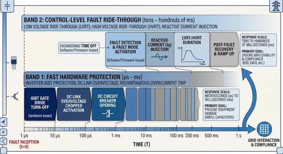
A PCS handles a fault in two layers. The layers operate on very different timescales. Both layers have to work correctly, or fault ride-through features never get the chance to activate.
Hardware-level protection reacts in microseconds to low milliseconds. Its only job is to keep the semiconductors from destroying themselves. It has no concept of a grid code.
Control-level ride-through reacts over tens to hundreds of milliseconds. This layer decides whether the PCS stays connected, injects reactive current, and follows the shape of the required curve.
If the hardware layer trips protectively, the control layer never gets the chance to ride through anything. Whichever layer is more conservative sets the PCS’s real fault ride-through capability — not the control algorithm alone.
Hardware-Level Fault Ride-Through Features
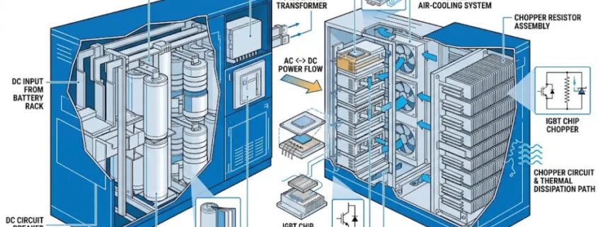
The fastest protection in a PCS sits at the gate-driver level. It senses the collector-emitter voltage of each IGBT to detect desaturation, a condition that signals an output short or a failing device. Engineers tune desaturation-sensing circuits deliberately to avoid nuisance tripping during normal switching transients. The circuits still have to catch a genuine fault fast enough to protect the device.
DC-Link Overvoltage Protection Features
Fault ride-through duty puts stress on the DC side, not just the AC side. During a grid voltage swell, or when active power suddenly can’t be exported at the pre-fault rate, energy backs up into the DC-link capacitor. Left unmanaged, this drives DC-link voltage past the semiconductors’ safe operating limit. The standard hardware answer is a brake chopper: a switch and resistor in series across the DC bus. The chopper circuit compares DC-link voltage against a threshold and switches accordingly, so it dumps excess energy as heat only when the bus voltage would otherwise exceed its saturation limit. Well-designed implementations fire the chopper only when needed. That way, the system wastes no energy during a swell the DC side can absorb on its own.
The wider category of hardware fault ride-through features for DC-link protection includes DC chopper resistors, dynamic braking resistors, and, in some designs, superconducting or bridge-type fault current limiters. These originated in wind turbine converters. The underlying function — dumping fault-driven excess energy somewhere the semiconductors can tolerate — applies directly to PCS design for solar and BESS.
Chopper sizing matters beyond a single event. A resistor sized to survive one fault safely can still overheat if the plant experiences repeated faults in close succession. Repeated faults are common on weak or fault-prone feeders. Duty-cycle rating, not just peak wattage, is the number to check when specifying the chopper.
Control-Level Fault Ride-Through Features
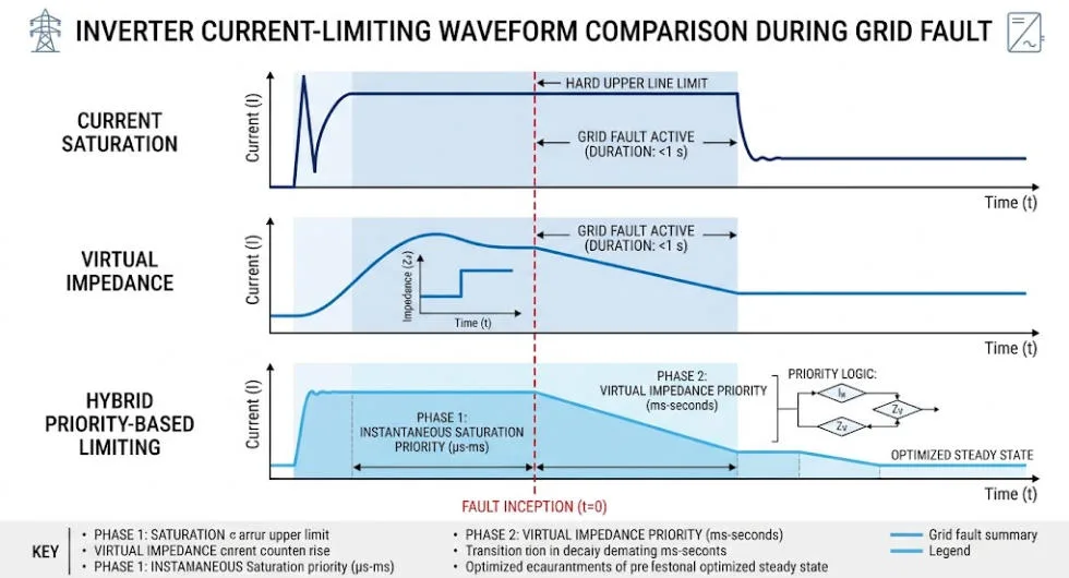
Once the hardware layer confirms the fault is survivable, the control layer decides how the PCS behaves for the rest of the ride-through window. This matters most for grid-forming PCS designs. Utility-scale BESS increasingly uses grid-forming designs because they set their own voltage reference rather than tracking the grid through a phase-locked loop. Three main control-level fault ride-through features keep grid-forming output current within hardware limits during a fault:
Current saturation: the controller switches into a current-controlled mode and fixes the current reference at the PCS’s maximum rated output for the duration of the fault.
Virtual impedance: the controller inserts an artificial impedance into its internal voltage-reference calculation. This lowers the commanded voltage in proportion to output current and limits current without a hard mode switch.
Priority-based saturation: a blended approach that combines current saturation and virtual impedance. It captures the current-limiting reliability of the first method with the smoother, more predictable transient response of the second.
Fault Ride-Through Features for Unbalanced (Asymmetrical) Faults
Most faults on a distribution or sub-transmission feeder are unbalanced — single-line-to-ground or line-to-line — not the symmetrical three-phase dip used in headline grid-code curves. Unbalanced faults introduce negative-sequence voltage and current components. A control loop built only for positive-sequence quantities can’t regulate these components correctly. Some grid-forming control architectures address this by working directly in the stationary reference frame rather than the conventional rotating (synchronous) frame. This design choice simplifies separating and limiting positive- and negative-sequence fault current independently. Engineers make this control-architecture decision well before a fault occurs — a plant controller can’t add it after the fact.
Fault Ride-Through Features That Differ Between BESS and Solar-Only PCS
A solar PCS has one energy source: whatever the array produces at that instant. It can curtail that output but not absorb energy. A BESS PCS has a battery on the DC side that can actively source or sink energy. That difference changes what fault ride-through features can actually do in practice.
During a voltage swell (HVRT), a BESS can charge from the surplus DC-side energy instead of dumping it through a brake chopper — but only if the BMS accepts a fast charge-current step, not just a steady-state charge-power limit.
State of charge and cell temperature set the real headroom. Near full SOC or at temperature extremes, the BMS derates charge current. That derating shrinks how much of a voltage swell the battery can absorb and pushes the PCS back toward reactive-current absorption or a supplemental dump resistor.
This means the PCS-BMS communication interface needs a fast current-limit path for ride-through events. That path has to run faster than the slower power-limit updates the system uses during normal charge/discharge scheduling.
None of this shows up on a PCS current-vs-time datasheet curve, because the curve is a converter-side spec. Whether the battery can actually support that curve under real SOC and temperature conditions is a system-level integration question, not a spec-sheet question.
Converter Topology and Fault Ride-Through Behavior
Topology choice shapes how fault current is distributed and controlled inside the converter itself.
Two-level converters concentrate fault current stress on fewer semiconductor devices per phase leg. This simplifies control but raises per-device stress during a fault.
Multilevel topologies (such as neutral-point-clamped or modular multilevel designs) spread that stress across more devices. They allow finer control of output voltage during unbalanced current injection, at the cost of more complex coordinated current-limiting logic across levels.
Plant-level topology matters too. Whether the site uses a string architecture or a small number of centralized PCS units changes how individual-unit current limits sum to the plant’s response at the point of interconnection. See our String vs. Centralized BESS PCS comparison for how that choice plays out beyond fault ride-through behavior.
Plant Controller Coordination for Fault Ride-Through Features
A single PCS unit’s current-limiting response is only half the picture. On a multi-inverter plant, the plant controller must aggregate every unit’s local response into a combined output at the point of interconnection (POI). That combined output has to match the required curve. Individual units sometimes apply current limiting independently, with slightly different thresholds or timing. When that happens, the combined POI response can differ meaningfully from what any single unit’s test report shows. Communication latency between the plant controller and individual PCS units becomes a real design constraint here. Ride-through windows can run as short as tens of milliseconds — too short for a slow polling cycle to matter.
Specifying Fault Ride-Through Features When Selecting a PCS
Treat fault ride-through features as a checklist to verify individually, not a single line item to take on faith.
Ask which current-limiting algorithm the PCS implements — current saturation, virtual impedance, or a priority-based blend — and how the manufacturer tuned the gain or setpoint, not just whether it claims a compliant curve.
Ask whether the manufacturer validated the DC chopper or dump resistor for repeated, closely spaced faults, not a single worst-case event.
Confirm the BMS charge-current step response time. Check whether it’s fast enough to support the PCS’s intended DC-side energy-absorption strategy during HVRT.
Confirm whether the unit is grid-following or grid-forming, and how its behavior changes during any momentary-cessation window.
Request fault-current test evidence at the plant-controller level, aggregating multiple units, not only single-unit type-test results.
Key Fault Ride-Through Features at a Glance
Feature
Why It Matters
Gate-driver desaturation detection
Fastest layer of protection; determines whether the control layer ever gets to ride through the fault
DC chopper / dump resistor
Keeps DC-link voltage within limits during a swell; duty-cycle rating matters more than peak wattage
Current saturation vs. virtual impedance vs. priority-based
Different trade-offs between reliability, reactive support, and transient smoothness
Positive/negative-sequence current control
Required for the unbalanced faults that dominate real-world fault statistics
BESS DC-side energy absorption
Lets a BESS actively soak up swell energy instead of only dissipating it — subject to SOC and thermal derating
Plant controller aggregation
Individual-unit compliance doesn’t guarantee POI-level compliance on a multi-inverter plant
Frequently Asked Questions About Fault Ride-Through Features
What’s the difference between hardware-level and control-level fault ride-through features?
Hardware-level features, such as IGBT desaturation detection, react in microseconds to protect the semiconductors. They have no awareness of grid-code requirements. Control-level ride-through features operate over tens to hundreds of milliseconds. This layer actually follows the required voltage-against-time curve. Hardware protection takes priority whenever the two layers conflict.
Why does a BESS have an advantage over a solar-only plant during HVRT?
A BESS can actively charge its battery to absorb surplus DC-side energy during a voltage swell. A solar-only PCS can’t do this — it has no equivalent energy sink beyond curtailing the array.
What is virtual impedance current limiting?
It’s a control technique where the inverter’s controller inserts an artificial impedance term into its internal voltage-reference calculation. This lowers the commanded output voltage in proportion to current and limits fault current without switching the converter into a different control mode.
Do all grid-forming inverters use the same fault ride-through features?
No. Implementations vary in whether they use current saturation, virtual impedance, or a priority-based combination. They also vary in whether they regulate unbalanced fault current in the stationary or synchronous reference frame. These are architecture-level decisions, not settings a plant operator can change after the PCS is built.
Why does DC chopper sizing matter beyond a single fault event?
A brake chopper resistor sized for a single worst-case fault can still overheat if the plant experiences repeated faults in a short period. Repeated faults are common on weaker feeders. Duty-cycle rating, not just peak wattage, determines whether the chopper survives real-world fault patterns.
AS/NZS 4777.2 Amendment 2 changed how Australia approves grid-connect inverters. Standards Australia published it on 23 August 2024. It became mandatory exactly one year later. Also, it now applies to every new grid-connect install. So any inverter installed today needs to meet it. So this guide covers every real change. It also covers the region settings you need to check, and what happened to inverters already on the approved list. It’s one of three standards in Australia’s new battery rules.
Quick Answer Quick answer: It became mandatory on 23 August 2025, after a 12-month transition. It makes six changes. New supply terms. Fewer tests for battery-only gear. New generation limit rules. Updated Region C set points. New paperwork rules. New clauses for two-way EV charging. Older CEC inverter listings didn’t carry over automatically. So manufacturers had to submit a declaration and evidence of the updated region settings before the deadline, or their models came off the approved list.
What Is AS/NZS 4777.2 Amendment 2?
AS/NZS 4777.2 is the standard that governs how grid-connect inverters behave once installed. It’s also Part 2 of a two-part standard. Part 1 covers general requirements. Part 2 covers the inverter-specific rules that matter most for design work. AS/NZS 4777.2 Amendment 2 is the second update to the 2020 edition. So it’s formally known as AS/NZS 4777.2:2020 Amendment 2:2024.
The Six Changes in AS/NZS 4777.2 Amendment 2
Six changes make up the bulk of AS/NZS 4777.2 Amendment 2. First, AS/NZS 4777.2 Amendment 2 updates supply type terminology, for clearer alignment with AS/NZS 4777.1. Then second, battery-only products no longer need IEC 62109 testing. That cuts duplicate certification work. Third, generation limit control parameters changed. Fourth, AS/NZS 4777.2 Amendment 2 updates Region C set points. Fifth, documentation and marking rules changed. Sixth, and most talked-about, new clauses cover electric vehicle supply equipment.
Change
What It Means
Supply type terminology
Updated for clearer alignment with AS/NZS 4777.1’s supply-type definitions
IEC 62109 removed
Battery-only products no longer need this testing, cutting duplicate certification work
Generation limit parameters
Control parameters for generation limiting were updated
Region C set points
Updated power quality set points specifically for Region C networks (Horizon Power, TasNetworks, remote Power & Water)
Documentation and marking
Updated requirements for product documentation and equipment marking
EVSE clauses (new)
New clauses covering electric vehicle supply equipment for bidirectional charging
When AS/NZS 4777.2 Amendment 2 Took Effect
So Standards Australia set a 12-month transition window. During that time, manufacturers could apply under the old or the new standard. After 23 August 2025, the Clean Energy Council only accepts Amendment 2 products for new listings. The Clean Energy Council runs this through its approved inverter list. Most network operators use that list directly.
What Happened to Existing CEC Inverter Listings
Existing listings didn’t need full re-testing for AS/NZS 4777.2 Amendment 2. Still, manufacturers had to prove compliance. The Clean Energy Council asked for a signed declaration. It also asked for proof of the updated region settings for every model. That proof could be a product manual, an install guide, or a screenshot from a monitoring app. Anything missing by 23 August 2025 meant the model came off the approved list. The Clean Energy Council’s standards-change page has the full manufacturer declaration template and process.
So this matters for anyone still specifying against an old product sheet. An inverter that was genuinely CEC-approved two years ago may not carry that status today. So always check the live CEC list at the point of design, not a cached copy from a previous project.
CSIP-AUS and Smart Communication
The updated standard introduced CSIP-AUS, the Common Smart Inverter Profile for Australia. Still, this is a communication protocol, not a hardware requirement. It lets network operators manage dynamic export limits, and in some cases apply remote curtailment. A compliant inverter under AS/NZS 4777.2 Amendment 2 lets the grid talk back to it, not just receive power one-way.
Region-Based Power Quality Settings
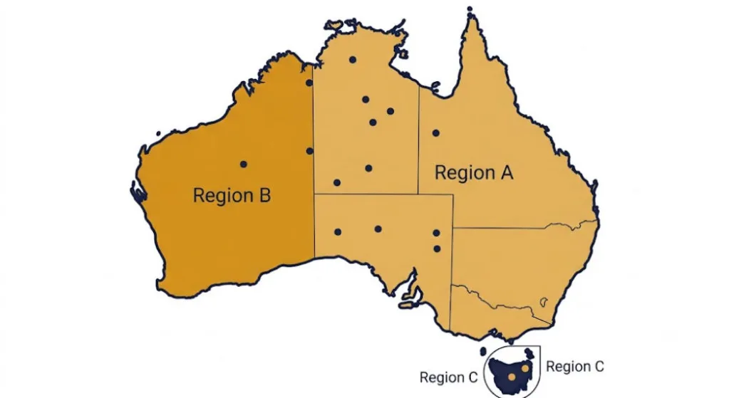
Power quality settings still follow a region-based structure: Australia A, B, or C. Most of the country falls under Region A. Western Power alone makes up Region B. Tasmania and remote areas fall under Region C, covering Horizon Power, TasNetworks, and remote parts of Power & Water. The full list is in the table below. AS/NZS 4777.2 Amendment 2 changed the Region C set points specifically. So a Tasmanian or remote WA install needs extra care here. Energy Networks Australia’s FAQ has the full DNSP contact list for each state.
Region
Distribution Network Service Providers (DNSPs)
Australia A
Ausgrid, AusNet Services, Endeavour Energy, Essential Energy, Ergon Energy, Energex, Evoenergy, Jemena, CitiPower, Powercor, United Energy, SA Power Networks, Power & Water (some areas)
Australia B
Western Power
Australia C
Horizon Power, TasNetworks, Power & Water (remote networks)
Warranty Replacement Rules
Warranty replacements get a narrow exception. Owners can still swap in an older-standard inverter under warranty, but only if three conditions hold together. The replacement has to be the same make and model. It has to genuinely be a warranty case. And the inverter has to match the existing connection agreement. Also, DNSPs still need to approve the replacement first. Outside those conditions, a warranty swap needs a current AS/NZS 4777.2 Amendment 2 compliant unit.
Bidirectional EV Charging: Mode 3 vs Mode 4
Bidirectional EV charging is where this amendment gets genuinely new. It’s not just a terminology refresh. So it splits two charging modes apart. Mode 4 charging sends power to and from the vehicle through wall-mounted gear with its own inverter. That gear now falls under AS/NZS 4777.2 Amendment 2 directly. It also sits inside the CEC’s approved inverter list. Mode 3 also sends power both ways, but the inverter lives inside the car instead. The Clean Energy Council is still working out how much of that setup falls under the same listing rules.
AS/NZS 4777.2 Amendment 2 Compliance Checklist
Confirm the specific inverter model against the live CEC approved list, not a cached spec sheet or marketing page.
Confirm the correct region setting (A, B, or C) for the installation’s DNSP — Region C set points changed under this amendment.
Check whether any EV charging equipment on the job is Mode 3 or Mode 4, since that determines which listing requirements apply.
For battery-only power conversion equipment, confirm whether the IEC 62109 exemption applies to the specific product.
If proposing a warranty replacement with an older-standard inverter, verify all three conditions: same make and model, genuine warranty case, and matching connection agreement.
Get DNSP approval before installing any warranty replacement inverter.
Frequently Asked Questions
When did AS/NZS 4777.2 Amendment 2 become mandatory?
Standards Australia published it on 23 August 2024. After a 12-month transition, it became mandatory for new inverter installations from 23 August 2025.
Does an old CEC inverter listing still work after Amendment 2?
Not automatically. Manufacturers had to submit a declaration and evidence of updated region settings before 23 August 2025. Any model without that evidence was removed from the approved list on that date.
What is CSIP-AUS?
CSIP-AUS is the Common Smart Inverter Profile for Australia — a communication protocol introduced with this amendment that lets network operators manage dynamic export limits and, in some cases, apply remote curtailment.
What’s the difference between Mode 3 and Mode 4 EV charging under this amendment?
Mode 4 charging uses wall-mounted Electric Vehicle Supply Equipment with its own inverter, which falls directly under AS/NZS 4777.2 and the CEC’s approved inverter list. Mode 3 charging also flows power both ways, but the inverter sits inside the vehicle instead — how that gets covered by the listing framework is still being finalised.
Can I still install an inverter that only meets the pre-Amendment 2 standard?
Only as a like-for-like warranty replacement, and only if the replacement is the same make and model, is genuinely for warranty purposes, and is set up to match the existing connection agreement. The DNSP still has to approve it first.
The BESS PCS — Power Conversion System — converts DC battery power to AC for loads or the grid. However, what a PCS must do beyond that basic job changes completely depending on the application. Consequently, choosing the wrong PCS type is one of the most expensive mistakes a project team can make.
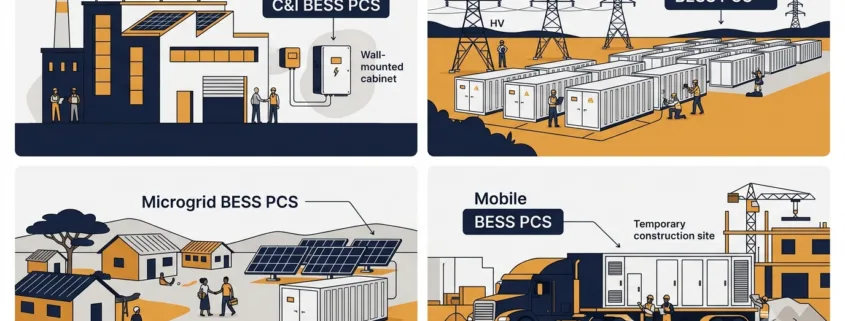
Consider four scenarios. A factory running peak shaving needs a PCS that switches to backup mode within 20 ms. By contrast, a 200 MW grid project needs sub-200 ms frequency response and reactive power control. An island microgrid, meanwhile, needs the PCS to synthesise the AC voltage reference — because no utility connection exists at all. Finally, a mobile BESS on a trailer needs ruggedness and fast site commissioning above all else.
Therefore, this guide covers each of the four application types in detail. Furthermore, it includes a master comparison table so you can see exactly which PCS functions are mandatory, optional, or not needed for each system type. By the end, you will have a clear framework for evaluating any BESS PCS proposal.
What Is a BESS PCS?
Inside every battery energy storage system, the Power Conversion System converts DC from the battery cells to AC for loads or the grid. During charging, it reverses direction and converts AC back to DC. Crucially, both functions share a single hardware platform — hence the term bidirectional.
As Sunlith’s PCS vs. Inverter guide explains, a PCS includes far more than just a bidirectional inverter. In addition, it handles reactive power control, protection functions, grid synchronisation, and communication with the BMS and EMS. According to NLR’s Power Electronics research, the PCS is one of the most critical components in grid-connected storage — because its control functions directly determine grid stability and service quality.
Moreover, the Bidirectional Inverter vs PCS comparison on this site highlights PCS-specific capabilities — including multi-port DC support, islanding, and black start. None of these are available in a stand-alone inverter. However, which of these capabilities you actually need depends entirely on your application type.
Four Application Types at a Glance
Before diving into each type, here is a quick overview showing how the four BESS application categories differ in their primary PCS priorities.
System Type
Typical Power
Grid Connection
Primary PCS Priority
C&I (Behind-the-Meter)
30 kW – 2 MW
Grid-connected, LV/MV
Peak shaving, backup power, solar integration
Utility Scale (Front-of-Meter)
2 MW – 500 MW+
Grid-connected, MV/HV
FFR, reactive power, grid code compliance
Microgrid / Off-Grid
10 kW – 50 MW
Islanded or weak grid
Grid-forming, black start, load following
Mobile BESS
50 kW – 5 MW
Temporary grid or off-grid
Portability, ruggedness, fast commissioning
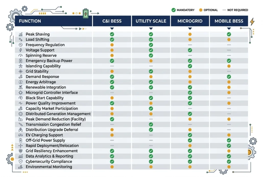
Master Comparison Table: BESS PCS Functions by Application Type
Use this table to compare PCS requirements across all four system types. Functions marked ✔ Mandatory must be specified and tested. Those marked ◉ Optional are recommended in certain site conditions. Those marked ✘ Not Required are not applicable to that system type.
PCS Function / Feature
C&I BESS
Utility Scale
Microgrid / Off-Grid
Mobile BESS
Bidirectional AC-DC Conversion
✔ Mandatory
✔ Mandatory
✔ Mandatory
✔ Mandatory
Peak Shaving / Load Shifting
✔ Mandatory
✘ Not Required
✘ Not Required
◉ Optional
Seamless Transfer / UPS Mode
✔ Mandatory
✘ Not Required
✔ Mandatory
✔ Mandatory
Solar PV Integration (AC/DC)
✔ Mandatory
◉ Optional
✔ Mandatory
◉ Optional
Fast Frequency Response (FFR)
✘ Not Required
✔ Mandatory
✘ Not Required
✘ Not Required
Primary Frequency Response (PFR)
✘ Not Required
✔ Mandatory
◉ Optional
✘ Not Required
Reactive Power (Q) Control
◉ Optional
✔ Mandatory
◉ Optional
✘ Not Required
LVRT / HVRT (Ride-Through)
◉ Optional
✔ Mandatory
✘ Not Required
◉ Optional
Grid-Following Mode (GFL)
✔ Mandatory
✔ Mandatory
◉ Optional
✔ Mandatory
Grid-Forming Mode (GFM)
✘ Not Required
◉ Recommended
✔ Critical
◉ Optional
Black Start Capability
✘ Not Required
◉ Optional
✔ Critical
◉ Optional
Droop Control
✘ Not Required
◉ Optional
✔ Critical
◉ Optional
Load Following
✘ Not Required
✘ Not Required
✔ Critical
◉ Optional
Genset Synchronisation
✘ Not Required
✘ Not Required
✔ Critical
✔ Mandatory
Time-of-Use (TOU) Scheduling
✔ Mandatory
✘ Not Required
✘ Not Required
◉ Optional
Multi-Port DC Input (PV + Battery)
◉ Optional
✘ Not Required
✔ Mandatory
◉ Optional
IEC 61850 / SCADA Integration
✘ Not Required
✔ Mandatory
◉ Optional
✘ Not Required
Modbus TCP / EMS Communication
✔ Mandatory
✔ Mandatory
✔ Mandatory
✔ Mandatory
Wide DC Input Voltage Range
✘ Not Required
✘ Not Required
✔ Mandatory
✔ Mandatory
Overload Capability (150–200%)
✘ Not Required
✘ Not Required
✔ Critical
✔ Mandatory
Compact / Trailer-Mount Design
✘ Not Required
✘ Not Required
✘ Not Required
✔ Critical
Rapid Commissioning (< 4 hrs)
✘ Not Required
✘ Not Required
✘ Not Required
✔ Critical
IP55+ Outdoor Enclosure
◉ Optional
✔ Mandatory
✔ Mandatory
✔ Critical
Noise Level < 65 dB(A)
✔ Mandatory
✘ Not Required
◉ Optional
◉ Optional
NERC CIP / Cybersecurity
✘ Not Required
✔ Mandatory
✘ Not Required
✘ Not Required
Legend: ✔ Mandatory = must be specified and verified at FAT | ◉ Optional = recommended for certain conditions | ✘ Not Required = not applicable
Which PCS functions are mandatory, optional, or not needed? This comparison covers all four BESS application types in one quick-reference chart.
C&I BESS PCS Functions and Features
A C&I — Commercial and Industrial — BESS sits behind the utility meter, serving loads inside a building or factory. Unlike utility systems, its PCS does not need to meet grid operator mandates. Instead, it must respond to site-level conditions to deliver financial returns. Specifically, the financial case comes from cutting demand charges, shifting energy to cheap tariff windows, and providing backup power during outages.
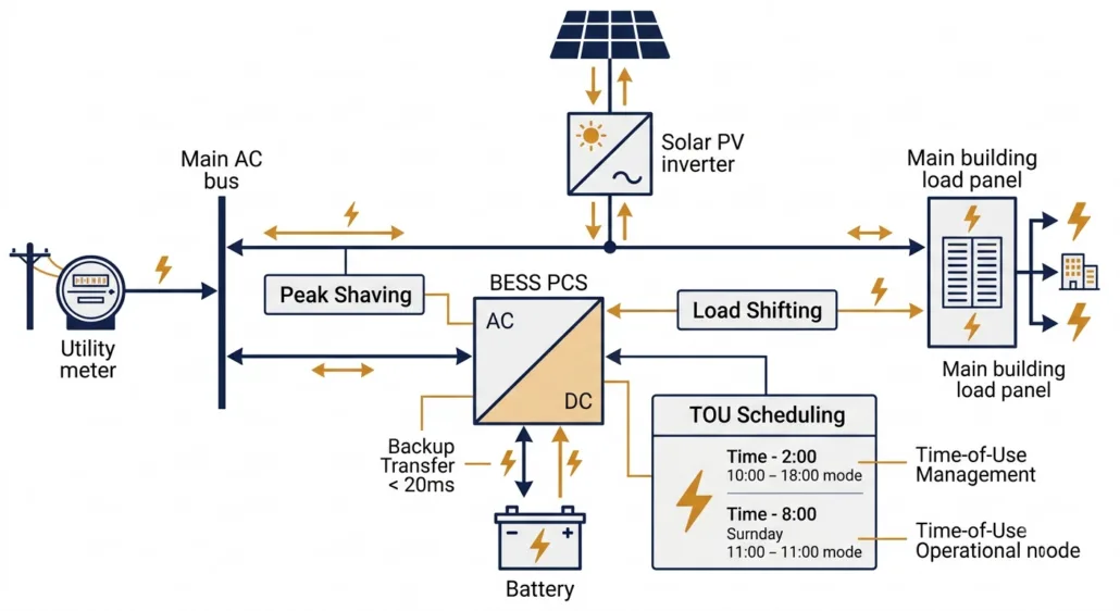
In a C&I system, the PCS manages power flow between the utility meter, solar array, and site loads — all simultaneously.
Peak Shaving and Time-of-Use Scheduling
Peak shaving is the most financially important C&I BESS PCS function. Demand charges can account for 30–50% of a commercial electricity bill. Therefore, the PCS charges the battery during low-demand periods and then discharges during peak demand to reduce the demand reading at the meter. Furthermore, time-of-use (TOU) scheduling shifts energy consumption into cheaper tariff windows, reducing energy cost on top of the demand saving.
Both functions require the PCS to support scheduled cycles via the EMS. Additionally, the PCS must respond to dynamic tariff signals from the utility in real time. As the IEA’s Grid-Scale Storage report notes, demand-side flexibility is one of the fastest-growing commercial storage applications globally. Consequently, TOU scheduling is now a baseline requirement in most C&I BESS tenders.
Seamless Transfer and Backup Power
When the grid fails, the C&I BESS PCS must switch to island mode fast enough to protect sensitive equipment. This transfer — called a seamless transfer or UPS mode — must complete within 20 ms for most commercial sites, and within 10 ms for data centres or precision manufacturing. Critically, seamless transfer is not a standard feature on all PCS products, so buyers must list the maximum allowed transfer time explicitly in their specification.
Furthermore, the PCS must be able to supply the full site load in island mode — not just a fraction of it. Therefore, both the transfer time and the island-mode power rating must be tested during factory acceptance testing (FAT). Accepting a vendor declaration without live testing is a common and expensive commissioning mistake.
Solar PV Integration
Most C&I BESS projects include rooftop or carport solar PV, so the PCS must integrate with the solar inverter. Two integration methods are available. AC coupling connects the solar inverter and PCS on the same AC bus — straightforward to retrofit, though energy passes through two conversion stages, which adds losses. DC coupling, by contrast, connects solar panels directly to the BESS DC bus via a DC-DC converter inside the PCS. This cuts conversion losses significantly. However, DC coupling requires the PCS to support multi-port DC input, so buyers must specify this feature explicitly at procurement stage.
C&I PCS Key Specifications
Power Range: 30 kW – 2 MW continuous output
Seamless Transfer: < 20 ms to island mode (< 10 ms for critical loads)
TOU Scheduling: Via EMS with dynamic tariff integration
Solar Integration: AC-coupled or DC-coupled PV input support
Grid Code: IEEE 1547 / UL 1741-SA for LV interconnection
Noise: < 65 dB(A) at 1 m for indoor installations
Communications: Modbus TCP to site EMS or BMS
Utility Scale BESS PCS Functions and Features
A utility-scale BESS connects to the medium or high-voltage grid in front of the meter. Consequently, its PCS must comply with grid operator requirements — legal obligations rather than performance suggestions. These requirements are more precise, more rigorously enforced, and technically more demanding than anything a C&I project faces. Therefore, a utility-scale PCS is a genuinely different machine from a C&I unit, even if the basic conversion function is the same.
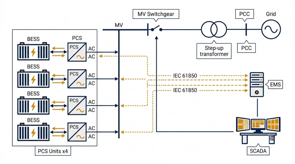
At utility scale, multiple PCS units run in parallel, feeding through a step-up transformer to the grid, with full IEC 61850 SCADA integration.
Fast Frequency Response (FFR)
FFR is the most commercially valuable utility-scale PCS function. When grid frequency drops — for example, because a large generator trips — the PCS must detect the deviation and ramp power within milliseconds. Most grid operators set the response window at 200 ms. However, some markets require 150 ms, and AEMO in Australia now tenders for sub-100 ms response.
To achieve these targets, the PCS control loop must use a dedicated high-speed frequency measurement algorithm — standard power quality meters are far too slow. Furthermore, the EMS-to-PCS communication link must have a round-trip latency below 50 ms, otherwise the communication delay consumes the available response window before the PCS even starts ramping. According to the US Department of Energy Energy Storage Grand Challenge, fast-responding battery storage is central to grid stability as thermal generation retires. Consequently, FFR is now a baseline commercial requirement for most utility-scale BESS contracts.
Reactive Power Control
Utility-scale BESS must provide reactive power — VAR — support to the grid. Under IEEE 1547-2018 in North America and EN 50549 in Europe, this function is mandatory. Specifically, the PCS must inject or absorb reactive power across all four quadrants of the PQ operating plane.
One critical detail: the PCS must deliver Q control even when the battery is at minimum state of charge — a requirement known as Q-at-night capability. Notably, some PCS products restrict reactive power output when the battery is in standby. Therefore, buyers must test Q-at-zero-kW operation during commissioning rather than rely on a datasheet claim alone.
Voltage Ride-Through: LVRT and HVRT
Grid codes require BESS to stay connected during voltage disturbances. LVRT — Low Voltage Ride-Through — means the PCS holds its grid connection during faults and injects reactive current to support the network voltage. According to ENTSO-E’s Network Code on Requirements for Generators, LVRT capability must extend down to 15% of nominal voltage for up to 625 ms. HVRT works in reverse — the PCS stays connected and absorbs reactive power during grid over-voltages.
Together, LVRT and HVRT define the voltage operating envelope of the PCS. Buyers must obtain the full voltage-time profile from the vendor and then verify it against the grid code at their specific point of interconnection. Requirements vary by country and operator, so this step cannot be skipped.
Grid-Following vs Grid-Forming at Utility Scale
Most utility-scale PCS units operate in grid-following (GFL) mode — synchronising to the grid via a Phase-Locked Loop and injecting current according to EMS setpoints. GFL works well on strong grids. However, as renewable penetration increases, grids are weakening and GFM capability is becoming more important.
Grid-forming (GFM) mode provides better fault current support and voltage stability on weak grids. As Sunlith’s Microgrid BESS technical guide notes, Australia already had over 1,070 MW of grid-forming BESS deployed by mid-2025. Therefore, GFM is mainstream technology, and buyers of utility-scale systems in high-renewable regions should evaluate it seriously.
Utility Scale PCS Key Specifications
FFR Latency: < 150–200 ms from event to ramp start
Q Control: Four-quadrant reactive power at all SOC levels including zero kW
LVRT / HVRT: Must match grid code voltage-time profile at PCC
DC Voltage: 1,000 V or 1,500 V DC to reduce cabling losses at scale
Communications: IEC 61850 GOOSE for deterministic low-latency dispatch
Cybersecurity: NERC CIP (North America) or IEC 62351 encryption
Certifications: IEEE 1547, EN 50549, AS/NZS 4777, UL 1741-SA — market-dependent
Microgrid and Off-Grid BESS PCS Functions and Features
Among all four application types, an off-grid or islanded microgrid BESS places the most demanding requirements on the PCS. No utility grid exists to act as a voltage and frequency reference. Consequently, the PCS must create that reference entirely from battery power. This changes nearly everything about how the system operates — from the control architecture down to the protection coordination.
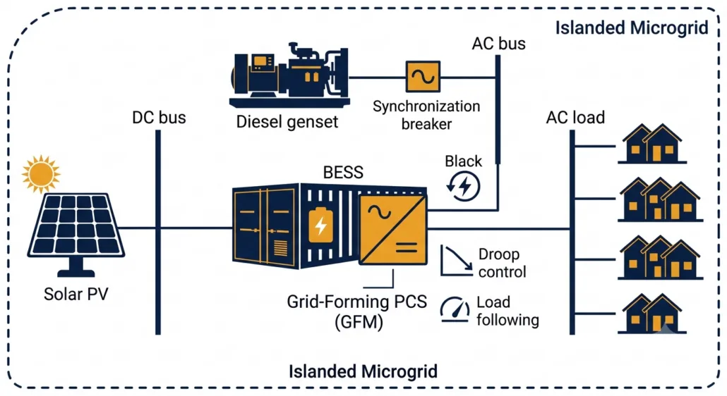
In an off-grid microgrid, the BESS PCS synthesises the local AC voltage and frequency from scratch — with no utility connection to lean on.
Grid-Forming Mode: The Non-Negotiable Requirement
Grid-forming (GFM) mode is the single most important requirement for any off-grid BESS PCS. Without it, the system simply cannot operate in an islanded environment. In GFM mode, the PCS synthesises the local AC voltage and frequency directly from battery DC power. All other devices in the microgrid — solar inverters, gensets, loads — then lock onto the PCS output as their grid reference.
This role is fundamentally different from a grid-connected system, where the PCS follows an existing grid reference. Consequently, GFM requires a completely different control architecture — it is not simply a software switch added to a grid-following PCS. Therefore, buyers must verify GFM certification through independent testing, not just through a vendor’s datasheet claim.
Black Start
Black start is the ability to energise a completely dead AC network from battery power alone, starting from zero volts. This function is essential for off-grid sites and increasingly mandatory for grid-scale microgrid contracts. However, it is also one of the most commonly missing features in PCS datasheets.
Specifically, black start requires the PCS to ramp up the AC bus voltage gradually — from zero — then connect loads in sequence as the voltage stabilises. Furthermore, close coordination with the protection scheme is needed to prevent fault currents during energisation. Therefore, black start must be tested and verified during commissioning. Listing it in a specification without on-site validation is not sufficient.
Droop Control and Load Following
In an islanded system, loads shift constantly and there is no external grid to absorb imbalances. Therefore, the PCS must continuously match its output to the instantaneous load demand — a function called load following. Droop control is closely related: it allows the PCS to share load automatically with a genset or another BESS unit by adjusting output in proportion to frequency or voltage deviations, without waiting for a central EMS command.
Consequently, droop control improves microgrid stability and allows multi-source systems to operate reliably even when the EMS communication link is temporarily lost. For these reasons, droop control and load following are both marked as critical requirements in the master comparison table above.
Genset Synchronisation
Many microgrids include a diesel or gas genset as a backup source. Before the interconnecting breaker closes, the BESS PCS must synchronise its output voltage with the genset — matching frequency, phase, and amplitude. Without proper synchronisation, inrush currents and voltage transients can damage both the PCS and the genset. Moreover, the PCS must manage transitions smoothly in both directions: when the genset starts up and when it shuts down.
Microgrid PCS Key Specifications
Grid-Forming Mode: Mandatory — PCS must synthesise local AC voltage and frequency
Black Start: Must be tested and certified on-site, not just listed in a datasheet
Droop Control: Autonomous load sharing without relying on EMS command
Load Following: Fast response to sudden load steps — no external grid buffer
Genset Sync: Smooth breaker closure with diesel or gas generators
Seamless Transfer: < 10 ms for critical load protection in island mode
Overload: 150–200% of rated current for 10 s to handle motor start loads
DC Voltage Range: Wide window to handle SOC swings without derating in island mode
Mobile BESS PCS Functions and Features
Mobile BESS units are trailer-mounted or containerised storage systems that travel between sites. Common applications include event venues, construction sites, disaster relief operations, emergency grid backup, and temporary peak demand support. Unlike fixed installations, however, mobile BESS PCS units must prioritise three things above all else: portability, ruggedness, and speed of deployment.
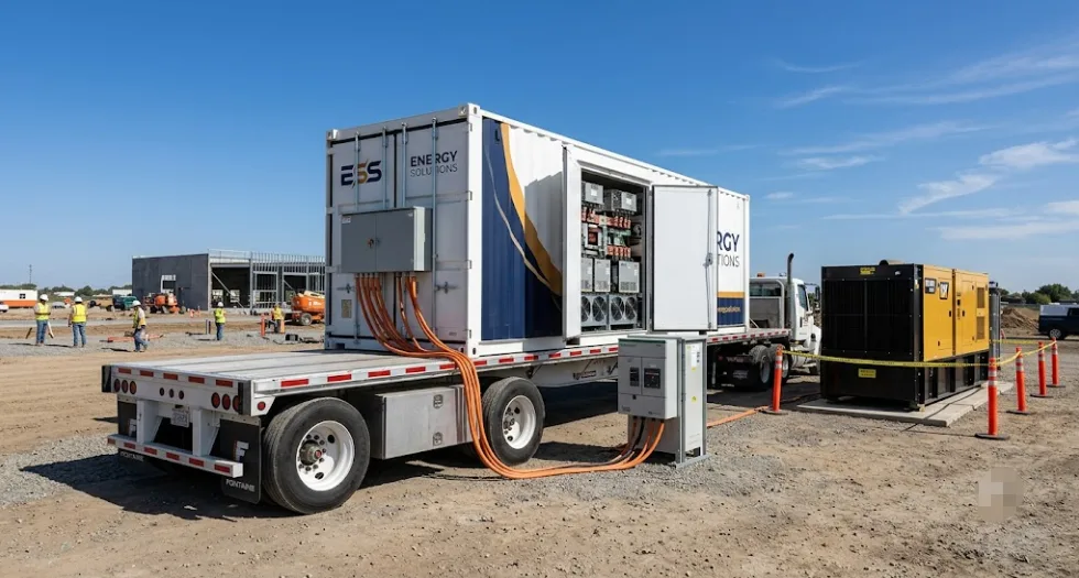
Mobile BESS units must reach full power output within hours of arriving on site — which demands a compact, rugged PCS with fast commissioning and multi-source compatibility.
Compact Design and High Power Density
Above all, a mobile BESS PCS must fit inside a trailer or small container. For this reason, power density is the primary design constraint — and liquid-cooled PCS units are preferred above 200 kW because they deliver more power per cubic metre and generate significantly less noise than air-cooled equivalents. Additionally, the PCS must tolerate vibration and shock loads during road transport, which standard stationary units are simply not designed to handle.
Rapid Site Commissioning
Speed of deployment is what sets mobile BESS apart from every other application type. A mobile BESS must reach full power output within a few hours of arriving on site — not the multi-week integration process typical of a permanent installation. Therefore, the PCS must support plug-and-play commissioning: pre-configured protection settings, automatic detection of local grid frequency (50 Hz or 60 Hz), and simple plug-in connections for power and communications.
Furthermore, the PCS must support multiple connection scenarios out of the box — temporary grid connection, islanded operation with a genset, or fully standalone off-grid mode. Consequently, mobile PCS units must include both grid-following and grid-forming capabilities as standard. Waiting for a firmware upgrade or specialist configuration on-site defeats the purpose of a mobile system.
Genset Integration and Overload Capability
Mobile BESS units frequently operate alongside diesel generators. Therefore, the PCS must synchronise with the genset smoothly and manage load transfers in both directions — when the engine starts and when it shuts down. Additionally, overload capability is a hard requirement for mobile deployments. Motor start loads on construction sites or industrial events can draw 150–200% of steady-state current for several seconds. A PCS that trips under this load makes itself useless.
Rugged Enclosure and Wide Temperature Range
Mobile BESS units deploy in unpredictable environments — muddy construction sites, outdoor festivals, flood-affected areas, and extreme climates. Consequently, the PCS must carry an IP55 or higher enclosure rating to resist dust and water ingress. Furthermore, the operating temperature window must extend well beyond typical stationary limits — many mobile PCS products are rated for operation between -25°C and +55°C and storage down to -40°C.
Mobile BESS PCS Key Specifications
Design: Compact, high power density; liquid cooling preferred above 200 kW
Transport Tolerance: Rated for road vibration and shock per IEC 60068-2
Commissioning Time: < 4 hours from arrival to full power output
Grid Frequency Auto-Detect: 50 Hz / 60 Hz without manual reconfiguration
Operating Modes: Grid-following and grid-forming built in as standard
Genset Sync: Smooth synchronisation and load transfer in both directions
Overload: 150–200% rated current for 10 s minimum
Enclosure: IP55 minimum; IP65 for harsh environments
Temperature Range: -25°C to +55°C operating; -40°C storage
PCS Functions Common to All Four Application Types
While each application type has unique demands, several PCS functions are universal. These baseline capabilities define what a PCS is — regardless of where it is installed or what grid code applies.
Bidirectional DC-AC Power Conversion
Every BESS PCS converts DC to AC during discharge and AC to DC during charging. Modern units reach peak conversion efficiency of 96% to 98.5%. However, round-trip efficiency matters more than peak figures. As Sunlith’s energy storage losses guide explains, power conversion is one of the four main loss categories in any BESS. Even a 1% PCS efficiency improvement compounds significantly across a 15-year project life — so it is worth specifying carefully.
BMS and EMS Communication
Two control layers interface with the PCS. Working from the bottom up: the Battery Management System (BMS) sends real-time charge and discharge limits — maximum current, minimum cell voltage, and thermal boundaries. These limits must always be respected by the PCS, including during high-priority grid response events. Above the BMS sits the Energy Management System (EMS), which sends power setpoints and operating mode commands to the PCS.
As Sunlith’s BESS communication protocols guide explains, the BMS transmits SOC, SOH, cell voltages, temperatures, current, and fault codes to enable safe and optimised dispatch. Consequently, the PCS-BMS-EMS communication stack is not merely a data link — it is a safety-critical control interface that must be validated end-to-end before commissioning.
DC-Side Battery Protection
Regardless of application type, all BESS PCS units must protect the DC bus from electrical faults. Key protection functions include over-current limiting, overvoltage protection and DC bus voltage regulation, pre-charge control to prevent capacitor inrush, earth fault detection, and short-circuit protection. Together, these functions protect the battery cells and reduce the risk of thermal runaway events. Therefore, buyers should always request the full DC protection relay specification — not just the AC circuit breaker ratings.
Key Technical Features to Specify in Any BESS PCS
Regardless of application type, the parameters below form a baseline specification checklist for any BESS PCS request for proposal (RFP).
Feature
Typical Range
Notes
Rated Power
30 kW – 10 MW per unit
Confirm continuous rating — not peak or 30-second duty
DC Voltage Range
600 V – 1,500 V DC
Must cover full battery SOC range without derating
AC Output Voltage
400 V / 690 V / 11 kV
MV output reduces transformer count at utility scale
Peak Efficiency
97% – 98.5%
Also request weighted average at your load profile
Power Factor Range
0.8 lead – 0.8 lag
Confirm Q capability at zero kW active output
FFR Response Time
< 100 – 200 ms
Verify against grid code at interconnection point
Grid-Forming Mode
Mandatory (microgrid)
Optional at utility scale; essential for off-grid
Seamless Transfer
< 20 ms C&I; < 10 ms off-grid
Test at FAT — do not accept a datasheet figure only
Communications
Modbus TCP / IEC 61850
IEC 61850 GOOSE for FFR; Modbus TCP for C&I dispatch
Certifications
IEEE 1547, UL 1741-SA, EN 50549
Request current certificates with expiry dates
Cooling
Forced air / Liquid-cooled
Liquid cooling preferred above 500 kW
Enclosure Rating
IP54 indoor; IP55+ outdoor
IP65 for mobile or harsh-environment sites
Warranty
5 – 10 years
Align with BESS project life of 15–20 years minimum
Relevant Standards for BESS PCS
Standards differ by region and application type. Always verify that certifications are current, geographically valid, and cover the specific grid code version in force at your interconnection point. Furthermore, check expiry dates — expired certifications are a common and avoidable cause of project delays.
Use this checklist when writing a BESS PCS request for proposal (RFP). Start with the application type — it determines which items below are mandatory.
Define application type: C&I, utility, microgrid, or mobile. This single decision shapes every other requirement.
Rated Power: Specify continuous AC output (kW) and DC input separately — not peak ratings.
DC Voltage Window: Confirm the PCS operates across the full battery SOC range without derating at either end.
Efficiency Curve: Request weighted average efficiency at your typical daily load profile, not only the nameplate peak value.
Grid-Forming Mode: Mandatory for microgrid. Specify if needed for weak-grid or mobile deployments.
Seamless Transfer Time: < 20 ms for C&I; < 10 ms for off-grid critical loads. Test at FAT without exception.
FFR Response Time: Define maximum latency from EMS setpoint to output ramp start — applicable to utility scale only.
Reactive Power: Specify power factor range. Confirm Q control works at zero kW active power output.
Black Start: Specify explicitly if required — not included in all PCS products. Test on-site.
Overload Capability: 150–200% rated current for 10 s — mandatory for microgrid and mobile types.
Commissioning Time: < 4 hours from arrival to full output — applicable to mobile BESS deployments.
Communications: Specify Modbus TCP, IEC 61850 GOOSE, or CAN Bus as required for your application.
Certifications: List required standards by jurisdiction. Request current certificates with expiry dates.
Enclosure Rating: IP54 for indoor; IP55+ for outdoor; IP65 for mobile or harsh-environment sites.
Inside a battery energy storage system, the Power Conversion System converts DC electricity from the battery to AC for loads or the grid. During charging, it reverses and converts AC to DC. Beyond this basic function, it also controls reactive power, responds to grid frequency and voltage events, and protects the battery. In off-grid systems, furthermore, it synthesises the local AC voltage and frequency reference from battery power alone.
Are C&I and utility scale BESS PCS units the same product?
No — they are significantly different. A C&I PCS focuses on peak shaving, load shifting, solar integration, and fast backup transfer. A utility-scale PCS, by contrast, must meet strict grid code requirements for FFR, reactive power control, and voltage ride-through. Consequently, you cannot simply scale up a C&I PCS for a utility project — the control architecture, communications, and certification requirements are fundamentally different.
Does an off-grid microgrid need a different PCS?
Yes, absolutely. A microgrid BESS PCS must operate in grid-forming mode — synthesising the local AC voltage and frequency without any external grid connection. In addition, it must support black start, droop control, load following, and genset synchronisation. None of these are required in most grid-connected applications. Therefore, always specify off-grid requirements explicitly in procurement documents — do not assume they are included.
What makes a mobile BESS PCS different from a fixed installation?
A mobile BESS PCS must be compact, transport-rated, and fast to commission on arrival. It must auto-detect local grid frequency and support both grid-following and grid-forming modes as standard. Furthermore, it must tolerate road vibration, wide temperature ranges, and variable site conditions that a stationary unit would never encounter. Consequently, mobile PCS units are a distinct product category — not simply a stationary PCS mounted on a trailer.
What efficiency should I expect from a BESS PCS?
Modern BESS PCS units reach peak efficiency of 97% to 98.5%. However, weighted average efficiency across a typical daily profile runs 1–2% lower than the peak figure. Therefore, always request the weighted average efficiency for your specific load profile — the nameplate peak value alone is not a reliable basis for energy yield calculations.
Which standards does a BESS PCS need?
Certification requirements depend on your project location and application type. In the US, IEEE 1547-2018 and UL 1741-SA are typically required. Meanwhile, Europe relies on the EN 50549 standard. For projects in Australia, AS/NZS 4777 is mandatory. Additionally, utility-scale projects in North America must meet NERC CIP cybersecurity requirements. See Sunlith’s Worldwide PCS Certification Guide for full details by country.
How Sunlith Energy Approaches BESS PCS Selection
At Sunlith Energy, we treat the PCS as one of the most important decisions in any energy storage project. Every engagement begins with an application analysis that defines the required operating modes, protection settings, and grid code obligations for that specific site. Furthermore, we verify certifications independently — rather than accepting vendor declarations without review.
Our team has evaluated PCS products across C&I, utility, microgrid, and mobile deployments. Importantly, we carry out PCS-EMS-BMS integration testing before any system leaves the factory. This ensures that communication protocols, protection coordination, and control modes are all validated end-to-end. Consequently, our clients avoid the costly commissioning surprises that arise when integration is left to the site team.
Contact the Sunlith Energy team if your project needs a BESS PCS specification review, vendor proposal evaluation, or commissioning support.
Selecting the right BESS PCS comes down to knowing your application. A C&I system needs peak shaving, backup transfer, and solar integration. A utility-scale project demands FFR, reactive power control, and full grid code compliance. An off-grid microgrid requires grid-forming mode, black start, and droop control. A mobile BESS, moreover, needs ruggedness, fast commissioning, and multi-mode operation out of the box. Therefore, there is no single PCS specification that fits all four scenarios — and trying to use one is a recipe for expensive rework.
Consequently, the first and most important step is to define your application type precisely. From there, use the master comparison table and specification checklists in this guide to build your PCS requirements. Furthermore, involve your PCS vendor early, verify certifications independently, and test all critical functions — especially seamless transfer, black start, and FFR — during factory acceptance testing before the system ships.
Sunlith Energy works with EPCs, project developers, and asset owners across all four BESS application types. Contact our team to discuss PCS requirements for your next project.
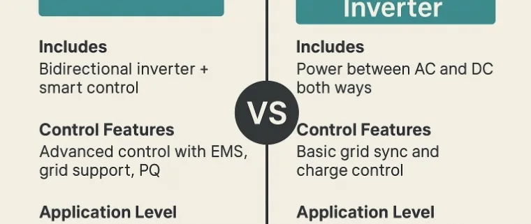
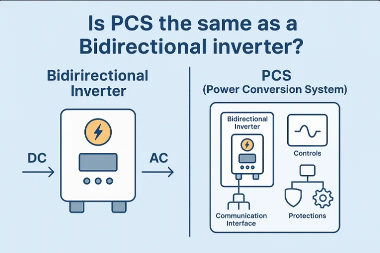
Bidirectional Inverter vs PCS: In the evolving world of energy systems, both Bidirectional Inverters and Power Conversion Systems (PCS) play a critical role—especially in energy storage systems (ESS), microgrids, and renewable power integration. While they appear similar in functionality, they are not interchangeable. In this blog, we break down every point of comparison, explain how each works, and where they are best used.
AC to DC Conversion: Converts grid AC to DC to charge batteries.
DC to AC Conversion: Converts stored DC back to AC to supply the load or feed the grid.
Grid Synchronization: Ensures power output is matched in voltage, frequency, and phase with the grid.
Battery Management Communication: Works with BMS to control charging/discharging safely.
⚙️ Usage Areas:
Home and commercial solar + battery systems
Microgrids
EV charging stations with V2G (Vehicle to Grid)
UPS systems with grid-tie capability
⚡ What Is a PCS (Power Conversion System)?
A PCS, or Power Conversion System, is a more comprehensive solution. It usually includes bidirectional inverter functionality, plus additional components such as:
Grid-interfacing controller
Communication interfaces
Safety protections
Advanced energy management algorithms
✅ Functions of PCS:
Bidirectional Power Flow: Handles charging and discharging like a bidirectional inverter.
Energy Management: Integrates with EMS (Energy Management System) for dynamic power flow.
Power Quality Control: Manages frequency, reactive power, and voltage.
Multi-port Control: Can connect multiple DC sources (PV, battery, etc.).
Islanding and Black Start: Supports off-grid operation and black start capability.
You need basic backup power and solar integration.
Budget is limited and advanced control isn’t a priority.
Choose PCS if:
You’re deploying a grid-scale battery system.
You need integration with grid operations or islanding capabilities.
You require smart control, power quality management, or multiple energy inputs.
📌 Bidirectional Inverter vs PCS: Real-World Example
Home System with Bidirectional Inverter: A solar home with a 10 kWh lithium battery uses a bidirectional inverter to charge the battery during the day and power the home at night. It synchronizes with the grid and works with a BMS.
Utility-Scale PCS Example: A 2 MW/4 MWh battery system at a wind farm uses PCS to manage energy injection into the grid during peak demand, support frequency regulation, and provide backup during outages.
🧠 Bidirectional Inverter vs PCS: Final Thoughts
Both Bidirectional Inverters and PCS are essential in the shift toward smarter, more resilient power systems. However, understanding their differences in function, scale, and intelligence is crucial before choosing the right solution.
In summary:
Use Bidirectional Inverter for basic energy conversion and storage in smaller systems.
Use PCS for smart, scalable, and grid-integrated power management in large or complex setups.
Bi-directional inverters are becoming a game-changer in modern energy solutions, especially within Power Conversion Systems (PCS). Whether in residential solar setups or large-scale Battery Energy Storage Systems (BESS), bi-directional inverters ensure seamless power flow in both directions—charging and discharging—between sources, storage units, and the grid. This blog post explores how they work, why they matter, and how they power smarter energy infrastructure.
What Is a Bi-Directional Inverter?
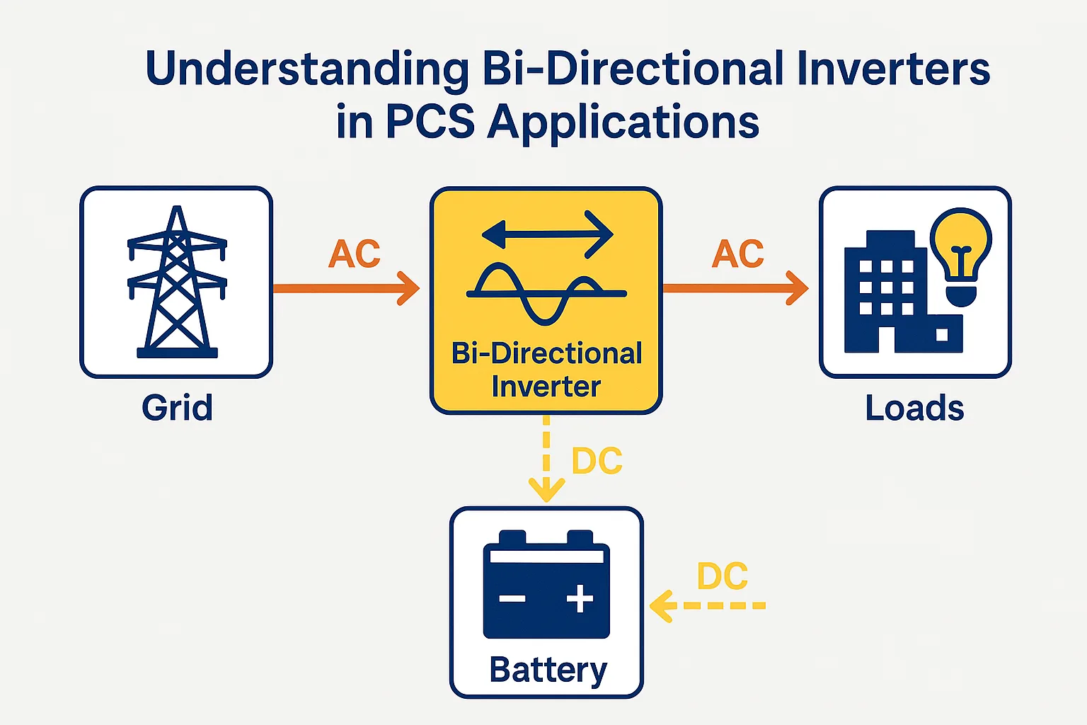
A bi-directional inverter is an advanced power electronic device that can both convert DC to AC (inverter mode) and AC to DC (rectifier mode). This dual functionality allows energy to move in two directions:
From the grid to batteries (charging)
From batteries to the grid or loads (discharging)
In PCS applications, this is crucial for load balancing, backup power, demand response, and optimizing energy costs.
Why Are Bi-Directional Inverters Important in PCS?
Power Conversion Systems (PCS) act as the interface between the energy storage system and the grid. The integration of bi-directional inverters offers several key advantages:
1. Grid Support and Frequency Regulation
They can feed power back into the grid or absorb it as required, enabling voltage/frequency stabilization, which is critical in renewable energy-heavy grids.
2. Flexible Load Management
During peak demand or outages, PCS with bi-directional inverters can redirect stored energy to critical loads.
3. Renewable Integration
They allow solar or wind energy to be stored and reused later, smoothing out the intermittency of renewables.
How Do Bi-Directional Inverters Work in PCS?
Charging Mode (Rectification)
When there’s excess power—such as from solar panels or the grid during off-peak hours—the inverter converts AC to DC and stores it in the battery system.
Discharging Mode (Inversion)
When power is needed, the stored DC energy is converted back to AC and used to power loads or sent to the grid.
This seamless switch between modes is managed by intelligent control algorithms within the PCS.
Applications of Bi-Directional Inverters in PCS
1. Battery Energy Storage Systems (BESS)
Large-scale storage units rely on bi-directional inverters for charge-discharge cycles, especially for grid-tied systems.
2. Microgrids
Enable isolated power operation and load sharing between solar, diesel generators, and batteries.
3. EV Charging Stations
Allow for vehicle-to-grid (V2G) energy transfer, where EVs serve as energy reserves.
4. Home and Commercial Energy Systems
Support self-consumption, energy arbitrage, and backup power during grid failure.
Key Technical Features of Bi-Directional Inverters
Smart Control Systems for dynamic energy flow management
Safety Mechanisms: Isolation, over-voltage, and thermal protection
These features make bi-directional inverters indispensable for smart energy ecosystems.
Benefits of Using Bi-Directional Inverters in PCS
Benefit
Explanation
Grid Interaction
Enables export/import of power to/from the grid
Energy Cost Optimization
Charge when prices are low; discharge when high
Resilience & Backup
Provide power during outages or peak load times
Renewable Maximization
Store excess solar or wind energy for future use
System Longevity
Controlled charge/discharge cycles improve battery life
Challenges and Considerations
Despite their many benefits, bi-directional inverters come with some technical and operational considerations:
Initial Cost: More complex and expensive than traditional inverters
System Complexity: Requires advanced control systems and integration
Regulatory Compliance: Must adhere to grid codes and safety standards
Thermal Management: Bidirectional use generates more heat, demanding better cooling solutions
Q&A About Bi-Directional Inverters
Q1: Can I use bi-directional inverters with solar panels?
Yes! They are ideal for solar systems combined with battery storage, allowing energy to be stored and used efficiently.
Q2: What makes them different from normal inverters?
Unlike regular inverters that only convert DC to AC, bi-directional inverters work both ways, supporting dynamic energy flows.
Q3: Are they suitable for off-grid systems?
Absolutely. In off-grid and hybrid systems, they provide enhanced energy control and backup capabilities.
Q4: Do they require special batteries?
Not necessarily, but high-efficiency systems often pair them with lithium-ion or other advanced battery chemistries for better results.
Real-World Use Case: Bi-Directional PCS in Smart Grid
In a commercial solar + storage project, a bi-directional PCS enables the facility to charge batteries during sunlight hours and discharge during peak demand, saving thousands on utility bills. The same system also provides blackout protection and participates in demand response programs, generating revenue.
Final Thoughts
Bi-directional inverters are at the heart of modern Power Conversion Systems. They’re more than just a technical upgrade—they’re a necessity for efficient, flexible, and intelligent energy management. As renewable energy and distributed generation continue to rise, so will the importance of these dual-purpose devices.
If you’re planning a BESS project, upgrading your commercial energy system, or simply aiming for smarter energy use, make sure to explore bi-directional inverters. They’re not just about converting power—they’re about empowering the future.
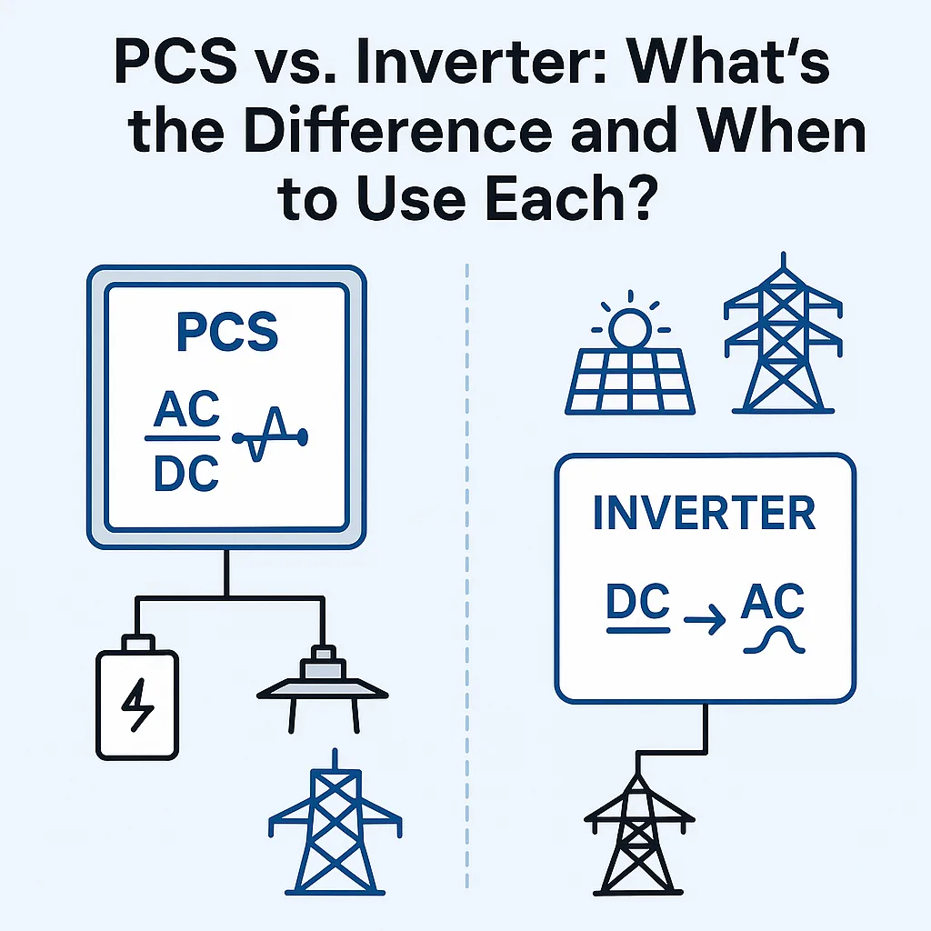
PCS vs. Inverter: When it comes to energy system components, terms like PCS (Power Conversion System) and inverter are often used interchangeably—but they are not the same. In the realm of modern energy storage systems (ESS), especially those connected to solar PV, EVs, or grid-scale applications, understanding the inverter vs PCS debate is critical for optimal design and performance.
Let’s break down the key differences, technical roles, and best-use scenarios to clarify your choices.
Understanding the Basics: Inverter vs PCS
What is an Inverter?
An inverter is a power electronic device that converts DC (Direct Current) electricity to AC (Alternating Current). This is essential for solar PV systems and battery packs that store electricity in DC but need to deliver power to appliances or the grid in AC format.
Function: DC to AC conversion
Common Use: Solar PV systems, UPS systems, small-scale battery applications
Types: String inverters, central inverters, microinverters
What is a PCS (Power Conversion System)?
A PCS is a broader system that performs bidirectional power conversion—both DC to AC and AC to DC—while also managing multiple other functions like voltage stabilization, frequency control, and reactive power compensation. It is a more intelligent, multifunctional energy interface between the battery system and the grid/load.
Function: AC-DC and DC-AC conversion with control logic
Common Use: Energy Storage Systems (ESS), microgrids, EV fast charging, utility-scale storage
Capabilities: Grid-forming, peak shaving, frequency regulation
Technical Comparison: Inverter vs PCS
Feature
Inverter
PCS (Power Conversion System)
Direction of Power Flow
One-way (DC to AC)
Two-way (DC-AC and AC-DC)
Intelligence & Controls
Basic
Advanced (EMS/BMS integrated)
Grid Interaction
Limited
Full (grid support, reactive power, etc.)
Energy Storage Support
Minimal
Full integration with ESS
Application Scope
Residential, Solar PV
C&I, Utility-scale, ESS, Microgrid
Communication & Protocols
Basic or none
Supports protocols (Modbus, CAN, etc.)
Roles in Energy System Components
Understanding the role each device plays in an energy system is key to proper ESS design.
Inverter’s Role in Solar Systems
Converts solar DC output into usable AC power
Often used in grid-tied residential and commercial systems
Not ideal for managing bidirectional battery storage
PCS Role in Energy Storage Systems
Acts as a bridge between AC grid and DC batteries
Controls power flow in both charge and discharge directions
Performs load shifting, peak shaving, and frequency regulation
Can operate in both grid-tied and off-grid modes
Use Case Scenarios: When to Use Which?
When to Use an Inverter
Simple Solar Systems: Use an inverter for small-scale solar PV systems without energy storage.
Backup Power: In residential UPS or emergency backup where power only flows one way.
Cost-Sensitive Projects: If the goal is just DC to AC conversion, inverters are cheaper and simpler.
Yes, you can find systems where both PCS and inverter are used—for example, a hybrid solar + battery system where the inverter handles solar generation and the PCS handles battery interaction and grid support.
This kind of layered architecture ensures reliability, especially in critical load centers and utility-scale applications.
ESS Design Tips: Choosing Between Inverter and PCS
When designing an Energy Storage System, consider these:
Is energy storage involved?
If yes, go with PCS.
Do you need two-way power flow?
PCS is designed for bidirectional conversion.
Are grid services like voltage support or peak shaving needed?
Only PCS can handle those.
Is this a standalone or grid-tied system?
PCS offers both modes; inverters are mostly grid-tied.
Frequently Asked Questions (FAQs)
Q1: Can I use a PCS as a simple inverter?
Yes, but it’s like using a supercomputer as a calculator—overkill and more expensive.
Q2: Is PCS required for all energy storage systems?
Yes, but it’s like using a supercomputer as a calculator—overkill and more expensive.
Q3: How does PCS integrate with EMS or BMS?
PCS acts as the executor of commands from EMS (Energy Management System) or BMS (Battery Management System), controlling charge/discharge, load balancing, and safety cutoffs.
Conclusion: Make the Right Choice for Your Energy System
Understanding the difference between PCS and inverter is vital for making smart decisions in energy system design. While both are critical energy system components, they serve different roles.
Use inverters when you need simple DC-to-AC conversion and use PCS when your application demands intelligent, two-way power flow and system-wide control—especially in ESS design.
Always assess your system’s needs before making the call. Choosing the right component can mean the difference between a basic power setup and a fully-optimized energy powerhouse.