
The Cost of Stranded Capacity: What Poor BMS Design Costs BESS Asset Owners
BESS financial models assume throughput follows a clean degradation curve. Real fleets don’t behave that way. Stranded capacity is the gap between the two.
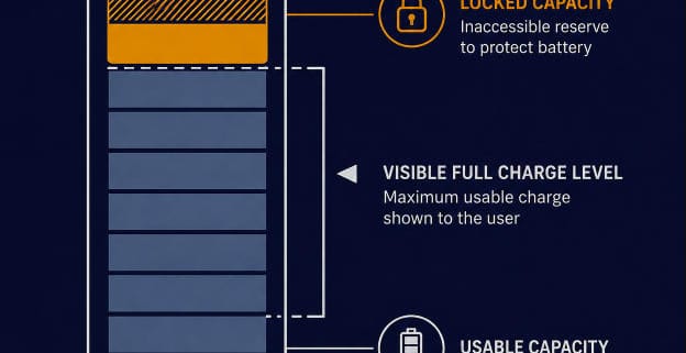
Every year, some capacity goes stranded. That’s capacity the pack technically still has, but the BMS can’t safely deliver it. Stranded capacity never shows up in a standard ROI model.
Our guide to calculating BESS ROI covers the standard model: capex, opex, revenue streams, payback period. This piece covers a value-at-risk category that model doesn’t capture.
Quick Answer
Stranded capacity is battery capacity a BESS has but can’t deliver, due to SOC drift, cell imbalance, or overly conservative cutoffs. It’s a hidden cause of revenue below projections. Fixing the underlying BMS design can recover real throughput — up to 10% in mid-to-late project life, in one internal analysis.
Key Takeaways
- Stranded capacity is real capacity the battery holds but the BMS can’t safely deliver. It’s a design and control issue, not a warranty defect or a safety problem by itself.
- One internal DCIR-adaptive cutoff analysis found up to 10% of effective throughput can be recovered in mid-to-late project life, just by replacing a fixed cutoff voltage with a DCIR-adaptive one.
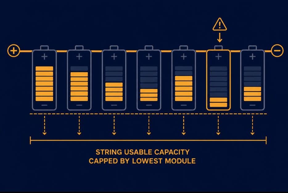
- Cell imbalance alone can strand real energy. A pack stops charging or discharging when its weakest cell hits a limit, well before the rest of the pack is full or empty.
- SOC estimation drift compounds silently. Left uncorrected, it produces wrong dispatch decisions and wrong revenue forecasts, not just an inaccurate percentage on a screen.
- None of these issues show up in a standard BESS ROI model’s assumptions. Asset owners and EPCs who ask about them at the RFP or commissioning stage catch value a generic warranty review misses.
Why Stranded Capacity Doesn’t Show Up in a Standard ROI Model
This is a different problem from capacity stranded by deliberate oversizing. See our BESS oversizing guide for that scenario, where idle nameplate capacity is a sizing choice, not a BMS malfunction. The stranded capacity covered here comes from BMS design and control issues on capacity the system was never meant to leave unused.
A standard BESS ROI model tracks one degradation number: State of Health. It assumes capacity fades on a smooth, predictable curve, and revenue scales down with it.
That model misses a second category entirely. Stranded capacity isn’t capacity the battery has lost. It’s capacity the battery still has, that the BMS can’t reach.
Our own DCIR-adaptive cutoff design analysis found this gap directly. A fixed low-voltage cutoff is sized conservatively for a fresh pack.
It stops discharge earlier and earlier as internal resistance rises with age.
A liquid-cooled BESS cycle-life comparison echoes the same finding. A DCIR-adaptive cutoff can recover up to 10% of effective throughput in mid-to-late project life.
That’s real revenue a fixed-cutoff design leaves on the table, every single cycle.
What Stranded Capacity Actually Looks Like
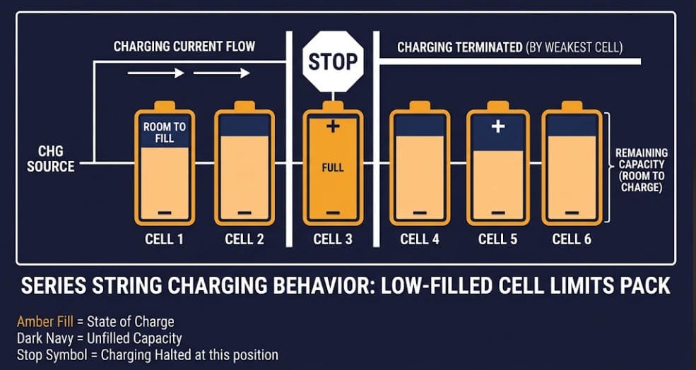
The mechanism is well documented in industry practice. Trade coverage of battery imbalance in BESS describes stranded energy this way: capacity that stays inaccessible because a small number of cells reach their limits first.
Charging can stop even though most of the pack still has room. Discharge can end while real energy still sits in the stronger cells.
Neither event trips an alarm. Neither shows up as a fault. The pack just quietly delivers less than it should, cycle after cycle.
Performance guarantees compound the problem. Industry analysis of BESS performance guarantees notes that a generic throughput guarantee often ignores which degradation mechanism actually applies.
Frequency regulation stresses a pack differently than energy shifting does.
A guarantee calibrated for the wrong use case can look satisfied on paper while stranded capacity quietly erodes real revenue underneath it.
Four Root Causes That Strand Throughput
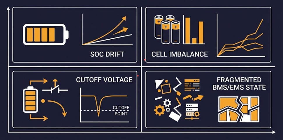
Stranded capacity has a small number of well-understood causes. Each one has a specific design fix, not just a monitoring dashboard.
SOC Estimation Drift
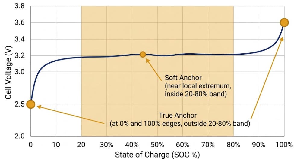
A BMS that only counts coulombs accumulates error every cycle, with no way to self-correct. Dispatch decisions built on a drifted SOC number are wrong, even when the battery itself is healthy.
This kind of drift is easy to miss because it doesn’t trigger any alarm. The dispatch software keeps making decisions confidently, just on the wrong number.
Over months, the gap between estimated and true state of charge can grow large enough to strand real capacity at both ends of the cycle — charge or discharge stopping based on a number that no longer matches reality.
See our EKF SOC estimation design guide for how a Kalman-filter-based estimator corrects for this instead of just counting and hoping.
In-Service Cell Imbalance
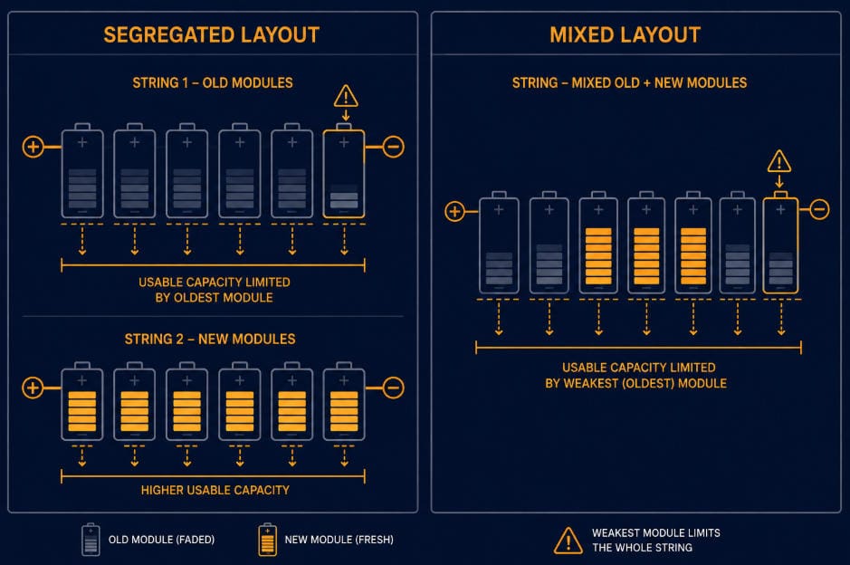
Cells drift apart in charge level over months of real-world cycling, even when they started out closely matched. The weakest cell then governs the whole string’s usable window.
Imbalance rarely announces itself either. Two cells built to the same spec can still diverge under real thermal and manufacturing variation, cycle after cycle.
Left uncorrected, that gap widens on its own. More of the pack’s true capacity quietly becomes capacity the BMS won’t touch.
See our in-service cell imbalance guide for how to detect and correct drift before it strands real capacity.
Premature Low-SOC Cutoffs
A fixed cutoff voltage, set conservatively for a brand-new pack, gets more conservative every year as internal resistance climbs. It ends discharge earlier than the chemistry actually requires.
The effect compounds quietly with age. A cutoff that was appropriately conservative in year one becomes needlessly conservative by year five, since resistance keeps climbing while the cutoff voltage stays fixed.
Nobody adjusts it, because nothing about the system looks broken. It just delivers a little less every year than it safely could.
See our DCIR-adaptive cutoff design guide for the design behind the 10% recovery figure cited above.
Fragmented BMS and EMS State
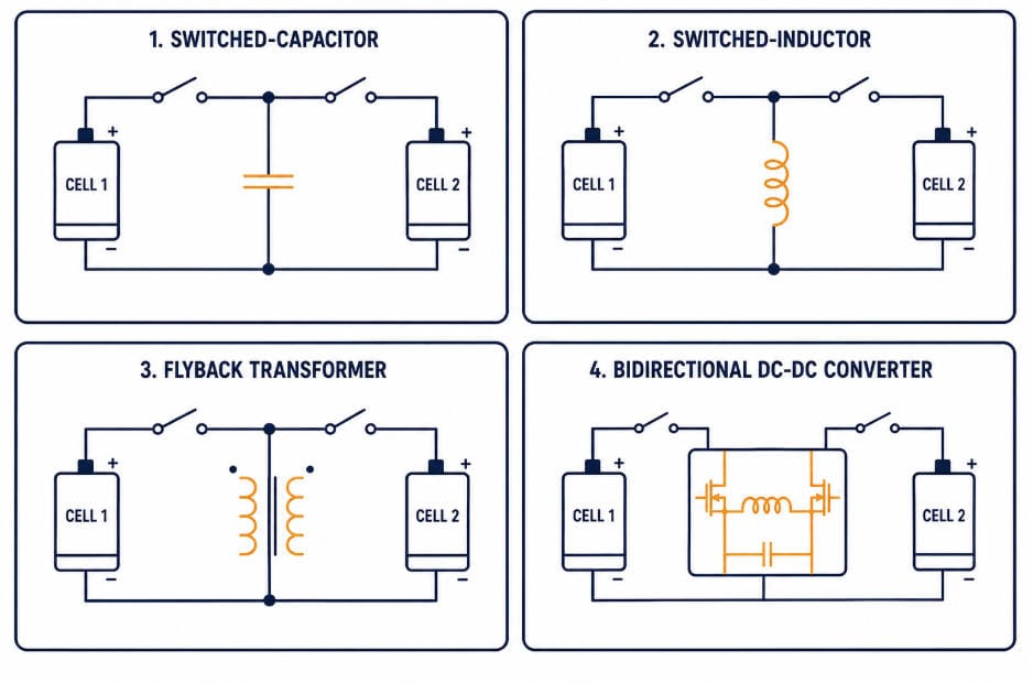
SOC, SOH, imbalance data, and cutoff logic often live in separate modules that don’t share state cleanly. Each module compensates conservatively for what it doesn’t know, and those safety margins stack up.
Each layer, acting alone, makes a reasonable decision. Stacked together, those decisions compound into capacity nobody intended to strand.
See our integrated BMS control architecture guide for how a shared-state design removes the guesswork each layer would otherwise carry on its own.
Root Causes, Symptoms, and Fixes at a Glance
The table below lines up all four causes of stranded capacity covered here, alongside how each one shows up and the design fix that addresses it.
| Root Cause | How It Shows Up | Design Fix |
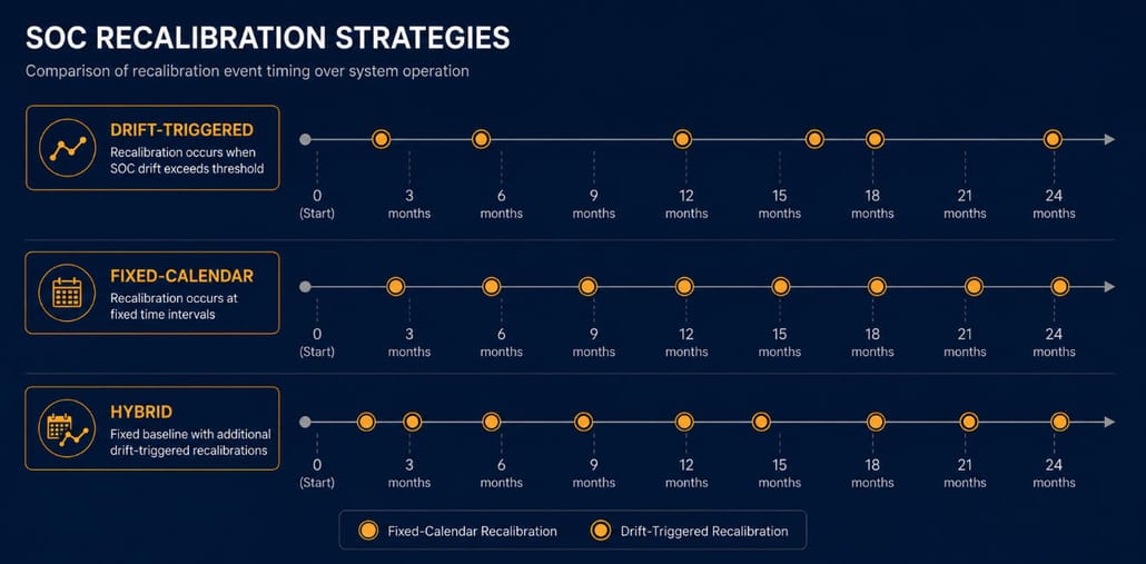
| SOC estimation drift | Wrong dispatch decisions; inaccurate revenue forecasts | Kalman-filter-based SOC estimation with periodic recalibration |
| In-service cell imbalance | String stops early on charge or discharge | Active balancing tuned to LFP’s flat voltage curve |
| Premature low-SOC cutoffs | Discharge ends before chemistry limits are reached | DCIR-adaptive cutoff voltage, not a fixed one |
| Fragmented BMS/EMS state | Conservative margins stack across separate modules | Integrated, shared-state control architecture |
Translating Stranded Capacity Into Revenue Terms
A simple illustration makes the scale concrete. Consider a 10 MWh system earning a blended $80 per MWh-cycle across arbitrage and grid services, cycling roughly 300 times a year.
That works out to about $240,000 in annual gross revenue at full throughput.
If stranded capacity quietly removes 5% of usable throughput, roughly $12,000 in potential annual revenue never gets captured. Not because the battery lacks the energy — because the BMS won’t release it.
At the higher end of the up-to-10% figure cited earlier, that figure roughly doubles to about $24,000 a year.
These are illustrative figures, not a forecast for any specific project. Actual revenue per cycle and stranded-capacity percentage vary by market, duty cycle, and system design.
But the exercise makes the point: stranded capacity deserves the same scrutiny during procurement as round-trip efficiency or a cycle-life warranty.
What This Means for Asset Owners and EPCs
Most procurement processes don’t ask about any of this directly. A typical RFP asks for round-trip efficiency, cycle-life warranty, and a capacity fade curve — all useful numbers, but none of them capture stranded capacity.
A vendor can meet every number on that list and still ship a BMS that strands a meaningful share of usable throughput.
None of these four causes show up in a standard capex/opex ROI model. They also rarely show up in a standard commissioning checklist.
A pack can pass acceptance testing and still strand capacity over its operating life.
The practical fix isn’t a new financial model. It’s a short set of design questions asked before contracts are signed, not after a project underperforms.
- Does the BMS use a fixed or DCIR-adaptive cutoff voltage, and how was that threshold validated?
- Does the SOC estimator include a correction mechanism, or does it rely on Coulomb counting alone?
- How does the BMS report cell imbalance, and what balancing current does it actually deliver?
- Do the BMS and EMS share state directly, or does each layer apply its own separate safety margin?
None of these questions require a vendor to reveal proprietary algorithm details. They just require a vendor who can explain, in plain terms, how the BMS handles SOC estimation, imbalance, and cutoff voltage as the pack ages — not just what it does on day one.
Asking these questions at the RFP or commissioning stage costs nothing. Discovering the answers three years into operation, in a shortfall against a revenue forecast, costs real money.
Sunlith Energy provides technical consultancy for BESS specification, BMS design review, and lifecycle modeling. Contact us to discuss where your project’s design may be leaving throughput stranded.
Frequently Asked Questions
Is stranded capacity the same as normal battery degradation?
No. Degradation is a real, permanent loss of capacity over time, tracked by State of Health.
Stranded capacity is different. It’s capacity the battery still physically has, that the BMS simply can’t reach.
Can stranded capacity void a BESS warranty?
Not directly. Warranties typically cover capacity retention against a defined degradation curve, not the BMS’s ability to access all available capacity. But a system that strands capacity may also look like it’s underperforming its warranty, which is worth raising with the integrator.
How much revenue does stranded capacity actually cost?
It depends heavily on the system, duty cycle, and root cause involved.
One internal analysis found up to 10% of effective throughput recoverable from a single fix: replacing a fixed cutoff voltage with a DCIR-adaptive one, in mid-to-late project life.
Can monitoring software alone fix stranded capacity?
Monitoring can reveal that capacity is being stranded, but it can’t fix the underlying cause on its own. SOC drift, cell imbalance, and conservative cutoffs are BMS design issues, not dashboard issues — they need to be corrected at the control-algorithm level.
Further Reading
For more on the design issues behind stranded capacity, and where this piece differs from adjacent site coverage:
BESS Oversizing: Pros, Cons & the Right-Sizing Strategy
Designing an LFP BESS Against SOC Drift, Cell Imbalance, and Premature Cutoffs
EKF SOC Estimation Design for LFP BESS
In-Service Cell Imbalance in LFP BESS
DCIR-Adaptive Cutoff Design for LFP BESS
Integrated BMS Control Architecture
The Economics of BESS: A Practical Guide to Calculating ROI
Sources
- Adding Efficiency and Better Performance to Battery Energy Storage Systems. Electrical Contractor Magazine, 2026
- Why BESS performance guarantees are more complex than they seem. Energy-Storage.News, 2026