EMS architecture is the control backbone of modern battery energy storage systems. It helps batteries operate safely, efficiently, and reliably. In addition, EMS architecture improves grid stability, renewable energy integration, and power management.
Today, battery storage systems support much more than backup power. They also help utilities balance electricity demand and stabilize renewable energy output. Therefore, smart control software is now essential.
At Sunlith Energy, advanced energy storage platforms use intelligent monitoring and automation to improve overall system performance.
What Is EMS Architecture?
EMS architecture refers to the structure that controls and manages a battery energy storage system. It combines software, communication systems, and hardware—such as Power Conversion Systems (PCS)—into one intelligent platform.
The system continuously collects real-time data. Then, it analyzes operating conditions and sends control commands.
For example, the EMS can:
Manage charging cycles
Prevent battery over-discharge
Balance grid demand
Improve energy efficiency
Monitor system safety
As a result, operators can improve both performance and reliability.
EMS Architecture and the 3S Framework
Modern battery systems use the 3S framework. This framework includes:
Battery Management System (BMS)
Power Conversion System (PCS)
Energy Management System (EMS)
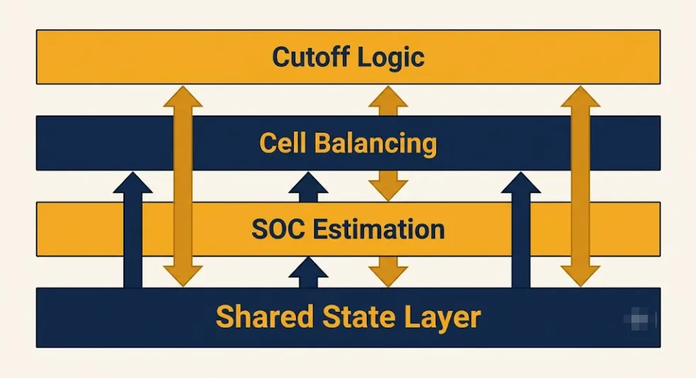
Each system has a different role. However, all three systems work together continuously.
Battery Safety and Monitoring
The Battery Management System protects battery cells from unsafe operating conditions.
The control platform operates continuously in real time.
First, it monitors grid conditions. Then, it analyzes battery data. Finally, it sends commands to the PCS and BMS systems.
This process repeats every second.
As a result, the storage system can maintain stable and reliable operation.
Future Trends in EMS Architecture
The global energy market continues to evolve rapidly.
As renewable energy adoption increases, EMS architecture will become even more important.
Future systems may include:
AI-based optimization
Predictive maintenance
Faster communication systems
Advanced analytics
Smart forecasting tools
Consequently, battery systems will become more efficient and intelligent.
Conclusion
EMS architecture is the operational brain of modern battery energy storage systems. It connects batteries, power electronics, and communication systems into one intelligent platform.
Through advanced monitoring and automation, operators can improve energy efficiency, grid support, and battery reliability.
At Sunlith Energy, integrated storage solutions support modern renewable energy and utility-scale applications.
FAQs
What is EMS architecture?
EMS architecture is the control structure used to manage communication, monitoring, and optimization inside battery energy storage systems.
Why is EMS architecture important?
EMS architecture improves system safety, grid stability, battery performance, and energy efficiency.
What are the three main parts of a battery storage system?
The three main components are:
Battery Management System (BMS)
Power Conversion System (PCS)
Energy Management System (EMS)
Technical Reference Guide
To better understand the individual components and metrics mentioned in this architecture, explore our deep-dive engineering guides:
Battery Performance: Learn why DC Internal Resistance (DCIR) is the true measure of a cell’s ability to handle high-power grid demands.
System Sizing: Use our Energy Storage Calculation Guide to determine the exact battery and solar capacity required for your architecture.
Safety & Compliance: A detailed breakdown of UL 9540A Test Methods for thermal runaway propagation.
BMS Evaluation: Download our checklist for Evaluating BESS Suppliers to ensure your BMS meets utility-scale standards.
⚡ Quick Answer: BESS Supplier BMS Evaluation in Brief In any BESS supplier BMS evaluation, ask for cell-level monitoring, SOC algorithm type, balancing current, fault response speed, SOH logging, certifications, and full test reports. A quality supplier answers all seven without hesitation. Vague answers, missing test data, or refusal to name the SOC algorithm are the clearest red flags.
A thorough BESS supplier BMS evaluation is one of the most important steps in any energy storage procurement. Most buyers spend hours comparing cell chemistry, capacity, and cycle life. Then they spend five minutes on the BMS. That gap is where expensive mistakes happen.
The battery management system determines whether a BESS is safe and whether its cells reach their rated life. Yet BMS quality is hard to verify from a spec sheet. Many suppliers use the same headline numbers — regardless of whether the implementation delivers those claims.
This guide gives you a practical BESS supplier BMS evaluation framework. Specifically, it covers the questions to ask, the documentation to request, and the red flags that reveal when a BMS falls short.
1. Why BESS Supplier BMS Evaluation Matters More Than Most Buyers Realise
A thorough BESS supplier BMS evaluation covers five areas: SOC accuracy, protection, balancing, certification, and data logging
The BMS is the hardest BESS component to evaluate from a spec sheet. Cells have measurable characteristics — capacity, internal resistance, cycle life. A BMS spec sheet, in contrast, often contains claims that are hard to verify without test data.
Consider two BMS platforms with identical spec sheets. Both claim 6,000-cycle compatibility, active balancing, and EKF SOC. One uses a properly calibrated EKF with cell-level monitoring. The other uses Coulomb counting relabelled as EKF and pack-level monitoring relabelled as cell-level.
In the field, the first system protects cells correctly and reaches its rated cycle life. The second degrades faster, shows erratic SOC readings, and fails early. Both had identical spec sheets.
Consequently, a structured BESS supplier BMS evaluation is the only way to tell them apart. Asking the right questions and requesting the right documentation must happen before you sign.
2. The Seven Questions Every BESS Supplier BMS Evaluation Must Include
These seven questions form the core of any BESS supplier BMS evaluation. Specifically, a credible supplier answers all of them without hesitation. Vague or evasive answers are red flags.
Question 1: Is Monitoring at Cell Level or Pack Level?
Cell-level monitoring tracks every individual cell voltage. Pack-level monitoring, however, tracks only the total pack voltage. These are fundamentally different levels of protection.
In a 16-cell LFP pack, one weak cell can hit its 2.5V limit while the pack reads 49V. A BMS monitoring only pack voltage misses this. As a result, the weak cell gets damaged and the pack degrades faster.
Cell-level monitoring is non-negotiable. Ask specifically: does the BMS monitor each individual cell voltage — or only the total pack? Pack-level only is an immediate disqualifier. For more on why, see our BMS guide.
Question 2: Which SOC Algorithm Is Used — and Is It Calibrated for This Chemistry?
SOC estimation is where most generic BMS platforms fall short on LFP. OCV-based SOC on LFP is unreliable during operation. Coulomb counting is the minimum standard. EKF is the most accurate option for systems above 200 kWh.
Ask two sub-questions. First: which method — OCV, Coulomb counting, EKF, or hybrid? Second: was the cell model calibrated for the specific cells in this system? An EKF with a mismatched model is often less accurate than well-implemented Coulomb counting.
Question 3: What Is the Balancing Current and Method?
Ask whether balancing is passive or active, and what the current is in milliamps. Residential systems under 30 kWh need 100 mA passive balancing. Commercial systems above 200 kWh need 200 mA or more. Active balancing is preferred above 500 kWh.
Indeed, a supplier who cannot state the balancing current either uses a low-quality BMS or does not know their product. Both are red flags.
Question 4: How Fast Does the BMS Respond to Faults?
Short circuit protection must activate in microseconds. This uses hardware circuits, not software. Thermal runaway protection must disconnect in under 100ms. Ask specifically for fault response times in the spec document.
A vague answer such as “the BMS has overcharge protection” is not enough. Response time is what matters. Slow fault response on NMC especially can mean the difference between a contained event and a fire.
Question 5: What Communication Protocols Does the BMS Support?
Confirm the BMS works with your specific inverter and EMS before signing. CAN bus and Modbus RTU are the most common protocols. Ask for a compatibility list showing which inverter models have been tested.
A protocol mismatch needs a gateway converter — adding cost, a failure point, and communication lag. Discovering this after delivery is also expensive and causes project delays.
Question 6: Does the BMS Log SOH and Cycle Data — and for How Long?
SOH logging is essential for warranty claims. Most BESS warranties guarantee a minimum SOH at a set cycle count. Without accurate SOH records, therefore, any warranty dispute becomes very hard to resolve in your favour.
Furthermore, from February 2027, EU Battery Passport compliance requires SOH history, cycle count, and energy throughput data. A BMS without adequate logging creates regulatory risk. For more on these requirements, see our EU 2023/1542 compliance guide.
Question 7: Which Certifications Does the BMS Hold — and Can You Provide Full Test Reports?
UL 1973, IEC 62619, and IEC 62933-5 are the key certifications for a BESS BMS. Always ask for full test reports — not just a certificate image. A certificate shows testing was done. A test report, however, shows what was tested, under what conditions, and what the results were.
If a supplier provides only a certificate image and cannot produce the full report, that is a serious red flag. Reputable suppliers keep test reports on hand.
3. BESS Supplier BMS Evaluation: Red Flags and Green Flags
Red flags and green flags in a BESS supplier BMS evaluation — what credible suppliers provide versus what evasive suppliers avoid
Red Flags: Signs a BMS Falls Short
Red Flag
What It Means
What to Do
🚩 OCV-only SOC on LFP
SOC will be inaccurate — erratic readings, wrong shutdowns
Require Coulomb counting or EKF with LFP-calibrated model
🚩 Pack-level voltage monitoring only
Cannot detect weak cell — will miss over-discharge events
Require cell-level individual voltage monitoring as standard
🚩 Cannot state balancing current
Low-quality BMS or supplier unfamiliar with their product
Request balancing current in mA from the spec sheet
🚩 No test report — certificate image only
Cannot verify what was actually tested or under what conditions
Require full test report from the certification body
🚩 Fault response time not specified
Cannot confirm short circuit or thermal protection speed
Require fault response time in ms in the spec document
🚩 No SOH logging capability
Cannot support warranty claims or EU Battery Passport compliance
Require SOH logging with timestamped cycle data
🚩 EKF claimed but no dynamic SOC accuracy data
May be Coulomb counting relabelled — not genuine EKF
Require SOC accuracy spec under dynamic load, not just at rest
Green Flags: Signs of a Credible Supplier
Green Flag
What It Means
What to Do
✅ Cell-level voltage monitoring confirmed
Weak cells will be detected and protected before damage occurs
Verify in test report
✅ SOC accuracy data under dynamic load provided
Genuine EKF or well-calibrated Coulomb counting
Cross-check against your application’s cycle profile
✅ Balancing current stated in spec sheet
Supplier understands their product and is transparent
Verify adequacy for your system size
✅ Full certification test reports provided
BMS has been genuinely tested under fault conditions
Check test temperature and conditions match your application
✅ Cell model calibration confirmed for specific cells
SOC estimation is tuned for actual cells in the system
Request calibration test report as evidence
✅ SOH logging with data export capability
Warranty claims and EU Battery Passport compliance are supported
Confirm export format and data retention period
4. Documentation to Request in a BESS Supplier BMS Evaluation
Questions reveal what a supplier claims. Documentation, however, reveals what they can prove. Request these six documents during any BESS supplier BMS evaluation — before signing.
BMS Technical Specification Sheet
Specifically, the spec sheet should state: cell voltage monitoring level, voltage accuracy in mV, SOC algorithm type, balancing current in mA, fault response times in ms, and communication protocols.
If any parameter is missing, ask for it in writing. A supplier who cannot provide this data does not have it — and that reveals something important about BMS quality.
Certification Test Reports
Request full test reports for UL 1973, IEC 62619, and IEC 62933-5. These reports specify the test conditions — temperature, voltage range, C-rate, and fault scenarios. They also show pass/fail results for each test item.
Pay attention to the test temperature. A BMS certified at 25°C may behave differently at 45°C in an outdoor enclosure. Ask whether certification was done at your actual operating temperature.
SOC Accuracy Test Data
Ask for SOC accuracy data under dynamic load — not resting accuracy. Specifically, the test should show SOC error during charge and discharge at varying C-rates and temperatures. Genuine EKF achieves ±1–2% under these conditions. If the supplier only has resting data, the SOC method is likely OCV-based.
Cell Model Calibration Report
If the supplier claims EKF, ask for the cell model calibration report. This confirms the EKF model was built and validated for the specific cells in the system. A generic EKF model, calibrated for different cells, will underperform.
Firmware Version and Update Policy
Ask for the current BMS firmware version and update policy. Ask whether OTA updates are supported and whether cell model updates can be deployed remotely. For 10–15 year systems, OTA capability is valuable — it keeps SOC accuracy high as cells age.
Field Reference List
Also ask for a reference list of installed systems using the same BMS platform. A few direct conversations with reference customers reveals real-world BMS performance that no spec sheet captures.
5. BESS Supplier BMS Evaluation by System Size
The depth of BESS supplier BMS evaluation needed scales with system size. Specifically, a 10 kWh residential install carries different risk than a 5 MWh commercial project. This section provides a tiered evaluation framework.
Residential BESS — Under 30 kWh
Residential systems have simpler BMS requirements. Key items to verify are cell-level voltage monitoring, a 0°C charge inhibit, and IEC 62619 certification. Coulomb counting SOC with OCV resets is the minimum SOC standard.
Passive balancing at 50–100 mA is adequate at this scale. SOH logging is also good practice — however, it is less critical for warranty purposes. The main risk is a BMS that allows over-discharge or cold-temperature charging. Both cause permanent cell damage.
Commercial BESS — 30 kWh to 1 MWh
Commercial systems need all seven questions from Section 2 addressed. SOC accuracy matters more at this scale. Dispatch contracts and self-consumption both depend on knowing available energy. EKF is therefore preferred above 200 kWh.
SOH logging becomes important at this scale for warranty compliance. Communication protocol compatibility with the site’s EMS is also critical — confirm this before delivery, not after.
Utility-Scale BESS — 1 MWh and Above
At utility scale, every aspect of the BESS supplier BMS evaluation matters. EKF is strongly recommended. A 5% SOC error on a 10 MWh system means 500 kWh of uncertainty. That directly affects revenue from grid services contracts.
Additionally, require master-slave architecture documentation, slave module independence verification, and a data logging spec that meets EU Battery Passport requirements for EU market systems.
6. How to Interpret Supplier Answers in a BESS Supplier BMS Evaluation
Knowing how to interpret supplier answers is as important as knowing which questions to ask. These, therefore, are the most common responses in a BESS supplier BMS evaluation — and what they actually mean.
Supplier Answer
What It Likely Means
Follow-up Required
“Our BMS has cell-level monitoring”
Could be cell-level or pack-level — the term is used loosely
Ask: how many voltage sensors are in a 16-cell module?
“We use advanced SOC algorithms”
Could mean anything — likely Coulomb counting marketed as advanced
Ask: specifically OCV, Coulomb counting, or EKF?
“Our BMS is EKF-based”
May be genuine EKF or may be lookup table relabelled
Ask: what is the SOC accuracy under dynamic load?
“We have all the certifications”
Certifications may be for cells only, not the full BMS system
Ask: UL 1973 or IEC 62619 specifically for the BMS?
“Our BMS has active balancing”
Active balancing design varies widely in quality and current
Ask: what is the balancing current in mA or A?
Provides full test report without being asked
Supplier is confident in their product and transparent
Green flag — review test conditions carefully
7. The BESS Supplier BMS Evaluation Checklist
BESS supplier BMS evaluation checklist — seven questions and six documents to request before signing a purchase order
Use this checklist when evaluating any BESS supplier’s BMS. A credible supplier completes all items. Any item left blank or answered vaguely is a prompt for further investigation.
Seven Questions — Minimum Answers Required
Q1: Cell-level or pack-level voltage monitoring?
Required answer: cell-level individual voltage monitoring, confirmed in the spec sheet.
Q2: SOC algorithm — OCV, Coulomb counting, EKF, or hybrid?
Required answer: Coulomb counting minimum. EKF preferred above 200 kWh. Cell model calibration confirmed for specific cells.
Q3: Balancing method and current in mA?
Required answer: specific mA value stated. 100 mA+ for residential. 200 mA+ for commercial. Active balancing for 500 kWh+.
Q4: Fault response time for short circuit and thermal events?
Required answer: short circuit response in microseconds. Thermal disconnect under 100ms confirmed.
Q5: Communication protocols and inverter compatibility?
Required answer: specific protocols stated. Compatibility with your inverter confirmed.
Q6: SOH logging — what data, how long, and what export format?
Required answer: SOH, cycle count, energy throughput logged. Retention period stated. Export format confirmed.
Q7: Certifications held and full test reports available?
Required answer: UL 1973 and/or IEC 62619 confirmed. Full test reports available on request.
Six Documents to Request
BMS technical specification sheet — with all parameters listed above
Full certification test reports — UL 1973, IEC 62619, IEC 62933-5
SOC accuracy test data — under dynamic load at relevant temperatures
Cell model calibration report — confirming EKF is tuned for specific cells
Firmware version and update policy — including OTA capability if applicable
Field reference list — installed systems at comparable scale using the same BMS platform
8. What a Strong BESS Supplier BMS Evaluation Response Looks Like
To give context to the checklist, here is what a strong, credible supplier response looks like for each key question. Use this as a benchmark when comparing suppliers side by side.
✅ Example 1. Strong Response — Cell Monitoring “Our BMS monitors each individual cell voltage using dedicated ADC channels — one per cell. In a 16-cell module, there are 16 independent voltage measurements sampled every 500ms. Cell-level monitoring is confirmed in our IEC 62619 test report, which we can provide.”
✅ Example 2. Strong Response — SOC Algorithm “We use an Extended Kalman Filter combined with Coulomb counting. The EKF cell model was calibrated for the EVE LF280K cells used in this system, at 15°C, 25°C, and 45°C. SOC accuracy is ±1.8% under 0.5C dynamic load. We can provide the calibration test report and the dynamic load accuracy data.”
🚩 Example 3. Red Flag Response — SOC Algorithm “Our BMS uses advanced intelligent SOC estimation technology that provides highly accurate state of charge monitoring in real time.” — No algorithm type named. No accuracy figure given. No test data offered. This is marketing language, not a technical answer. Follow up with the specific sub-questions from Section 2 immediately.
Conclusion: Make BESS Supplier BMS Evaluation a Standard Step
A BESS supplier BMS evaluation is not a technical exercise reserved for engineers. It is a procurement discipline that any buyer can apply with the right questions and the right checklist.
The seven questions and six documents in Section 7 take less than an hour to work through. That hour protects against BMS failures that cost far more to fix in the field.
The clearest signal of a credible supplier is transparency. Credible suppliers answer the seven questions clearly and provide full test reports without hesitation. Evasive or vague answers, in contrast, are the most reliable red flag in any BESS supplier BMS evaluation.
☀️ Need Help with Your BESS Supplier BMS Evaluation? Sunlith Energy reviews BMS specifications and supplier documentation for BESS projects from 50 kWh upward. We apply this checklist on your behalf — identifying gaps in protection architecture, SOC accuracy, and certification compliance before you commit. Contact us
Frequently Asked Questions About BESS Supplier BMS Evaluation
What is the most important question in a BESS supplier BMS evaluation?
Cell-level voltage monitoring is the most important single question. A BMS that monitors only pack voltage cannot protect individual cells from over-discharge or overcharge. This failure mode causes faster degradation across the entire pack. Every other BMS feature is secondary to getting this protection right.
How do I know if a supplier is using genuine EKF or just claiming it?
Ask for SOC accuracy data under dynamic load — not resting accuracy. Genuine EKF achieves ±1–2% during active charge and discharge. If the supplier gives only resting data, the SOC method is likely Coulomb counting or OCV. Also ask for the cell model calibration report.
What certifications should a BESS BMS hold?
For most commercial BESS, UL 1973 and IEC 62619 are the primary certifications to require. IEC 62933-5 covers the ESS safety framework and is relevant for grid-connected systems. For EU market access after 2027, the BMS must also support the EU Digital Battery Passport data requirements. Always ask for full test reports.
Can I evaluate a BESS supplier’s BMS without technical expertise?
Yes. These questions require no engineering background. The answers either contain the information required — algorithm type, balancing current, fault response time — or they do not. A credible supplier gives specific answers. An evasive supplier gives vague, non-specific ones. That distinction is clear without technical expertise.
What happens if I skip the BESS supplier BMS evaluation?
The risks are real and specific. A BMS without cell-level monitoring allows weak cells to be over-discharged, accelerating degradation. Poor SOC estimation causes unnecessary shutdowns and wasted capacity. Missing SOH logging makes warranty disputes nearly impossible to win. For a 10-year BESS project, these failures compound significantly over time.
⚡ Quick Answer: What Is a Battery Management System? A battery management system (BMS) is the electronic brain inside every lithium battery pack. It monitors cell voltage, current, and temperature in real time. It also protects cells from overcharge, over-discharge, short circuit, and thermal runaway. Furthermore, it estimates State of Charge (SOC) and State of Health (SOH). Without a BMS, a lithium battery is both unsafe and short-lived.
Every lithium BESS relies on a battery management system to run safely. This is true for a 10 kWh home install and a 10 MWh grid system alike. In both cases, therefore, the BMS is not optional — it sits between your cells and everything that can destroy them.
Yet the BMS is one of the most overlooked parts of any BESS purchase. Buyers focus on cell chemistry, capacity, and cycle life. Then they treat the battery management system as a given. That is a costly mistake.
A poor BMS, therefore, degrades good cells. A great battery management system, in contrast, extends the life of average cells. It is a lifespan management tool — not just a safety device.
This guide explains how a battery management system works, what it monitors, and how it balances cells. We also cover SOC and SOH calculation and show you how to evaluate a supplier’s BMS before you sign. For context on how the BMS interacts with cell chemistry, first read our LiFePO4 vs NMC battery comparison guide.
1. What Is a Battery Management System?
How a battery management system connects cells, inverter, EMS, and monitoring platform
A battery management system (BMS) is an electronic control unit built into a battery pack. Specifically, its job is to protect cells, measure their state, and report data to the rest of the system.
Think of the BMS as doing three jobs at once. First, it acts as a protection circuit — preventing electrical and thermal damage to the cells. Second, it is a measurement system — tracking voltage, current, temperature, SOC, and SOH. Third, it is a communication hub — sending live data to the inverter, EMS, and monitoring platform.
In a simple 12V residential pack, the BMS is a small PCB inside the module. In a commercial BESS, however, it manages hundreds of cells at once. The scale changes — but the core functions stay the same.
🔋 Why the Battery Management System Determines Lifespan Two identical cell packs with different BMS implementations deliver very different lifespans. Specifically, a BMS that allows cells to hit voltage limits, run hot, or drift out of balance will shorten cell life — regardless of the chemistry’s rated cycle count. The battery management system is, therefore, as important as the cells themselves.
2. Battery Management System Functions: The Seven Core Jobs
A well-designed battery management system performs seven distinct functions. Each one protects the battery in a different way. Together, furthermore, they determine whether your BESS is safe, efficient, and long-lived.
2.1 Cell Voltage Monitoring
The BMS monitors every individual cell voltage — not just overall pack voltage. This matters because cells in a multi-cell pack drift apart over time. Specifically, one weak cell can hit its limit before the others do.
For LiFePO4 cells, the safe range is 2.5V to 3.65V per cell. Going outside this range — even briefly — causes permanent capacity loss. So the BMS must, therefore, detect and respond to violations in milliseconds.
Voltage monitoring also underpins SOC estimation, which we cover in Section 5. Without accurate cell-level data, furthermore, everything else the BMS does becomes unreliable.
2.2 Current Monitoring and Overcurrent Protection
The BMS measures charge and discharge current using a shunt resistor or Hall-effect sensor. Specifically, this data serves four purposes:
Coulomb counting — integrating current over time to estimate SOC
Overcurrent protection — detecting short circuits and excessive discharge rates
C-rate enforcement — ensuring cells never charge or discharge faster than their rated speed
Power limiting — reducing available power as SOC drops or temperature rises
2.3 Temperature Monitoring
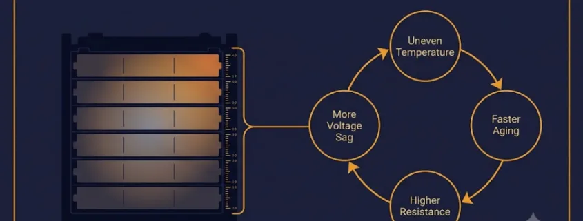
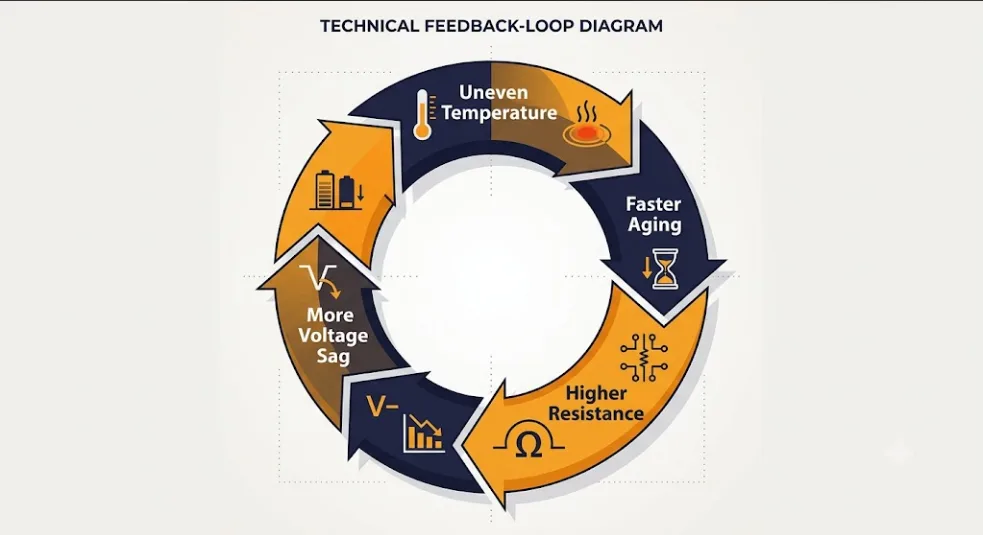
Temperature is one of the biggest drivers of battery degradation. Consequently, the BMS places sensors at multiple points — cell surfaces, busbars, and the enclosure. It uses this data to trigger cooling and reduce current.
It also halts charging below 0°C. Charging below freezing causes lithium plating. This is permanent anode damage that cannot be reversed.
For LiFePO4, the safe charging range is 0°C to 45°C. Discharge, however, runs across a wider range of -20°C to 60°C. The BMS enforces both limits automatically.
2.4 Overcharge and Over-Discharge Protection
These are the two most critical BMS protection functions. Overcharging a lithium cell causes irreversible changes in the cathode. Similarly, over-discharging collapses the anode. Both permanently reduce capacity.
The BMS prevents both by triggering a contactor disconnect when any cell breaches its voltage limit. This happens even if the pack’s overall voltage looks normal. One weak cell can hit its limit while others still have headroom. That is why cell-level monitoring is non-negotiable.
2.5 Short Circuit Detection and Response
A short circuit sends a massive current spike through the pack in milliseconds. Without protection, the heat this creates can trigger thermal runaway. As a result, the BMS detects the spike and opens the contactor in microseconds — before damage occurs.
Furthermore, sustained overcurrent protection prevents operation at damaging C-rates. This applies even without a sudden short circuit event.
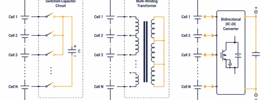
2.6 Cell Balancing
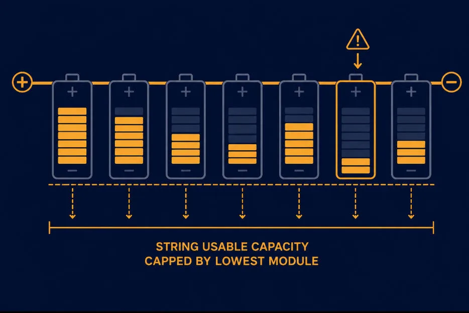
Cell balancing is one of the most important long-term BMS functions. It keeps all cells at the same State of Charge. Without it, the weakest cell limits the entire pack — even though the others still have energy to give.
We cover passive vs. active balancing in detail in Section 4. The key point, however, is this: balancing quality directly affects how much rated capacity you can use over time. In other words, poor balancing means lost energy.
2.7 Communication and Data Reporting
A modern battery management system communicates with the inverter, EMS, SCADA, and remote monitoring platforms. In particular, the most common protocols include:
CAN bus — standard in high-performance BESS and automotive applications
RS485 / Modbus RTU — common in commercial and industrial storage
MQTT / TCP-IP — used for cloud monitoring and Battery Passport data exports
The BMS transmits SOC, SOH, cell voltages, temperatures, current, cycle count, and fault codes. Specifically, this data feeds dispatch decisions in the EMS and enables remote health tracking.
3. Battery Management System Architecture: Three Tiers Explained
BMS architecture scales with system size. Specifically, there are three implementation levels. Each one adds capability and complexity.
BMS Tier
Also Called
Scope
Typical Application
Cell-level BMS
CBMS
Monitors individual cells in one module
Residential storage under 30 kWh
Module BMS
Slave BMS / MBMS
Manages one group of cells in a module
C&I systems, EV battery packs
System / Master BMS
SBMS / Master BMS
Coordinates all modules in the full pack
Utility-scale BESS, multi-rack systems
Single-Level BMS (Residential)
In smaller systems — typically under 100 kWh — a single BMS manages all cells directly. This is a simple, low-cost architecture. Consequently, the BMS PCB sits inside the battery module and handles monitoring, protection, and balancing on its own.
However, as cell count grows, wiring becomes complex and processing load increases. Beyond a certain size, single-level BMS becomes impractical.
Master-Slave BMS (Commercial and Utility Scale)
In larger systems — typically above 100 kWh — a master-slave design is used. Each battery module has its own Slave BMS. It handles local cell monitoring and balancing. All Slave units then report to a central Master BMS, which coordinates the full system.
The Master BMS aggregates data from all modules and manages system-level protection. Furthermore, it communicates with the inverter and EMS. As a result, this architecture scales well to multi-megawatt-hour systems.
⚠️ Key Evaluation Point: Master-Slave Independence In a quality master-slave battery management system, each slave module should protect its own cells independently — even if communication with the master is lost. A BMS where cell protection depends entirely on the master, however, creates a single point of failure. Therefore, always ask: what happens to cell-level protection if the master controller fails?
4. Cell Balancing in a Battery Management System: Passive vs. Active
Passive balancing dissipates excess charge as heat. Active balancing transfers charge between cells electronically.
Why Cells Need Balancing
No two lithium cells are identical. Manufacturing tolerances mean cells leave the factory with slightly different capacities. Moreover, temperature gradients within a pack cause some cells to age faster. Self-discharge rates also vary slightly between cells.
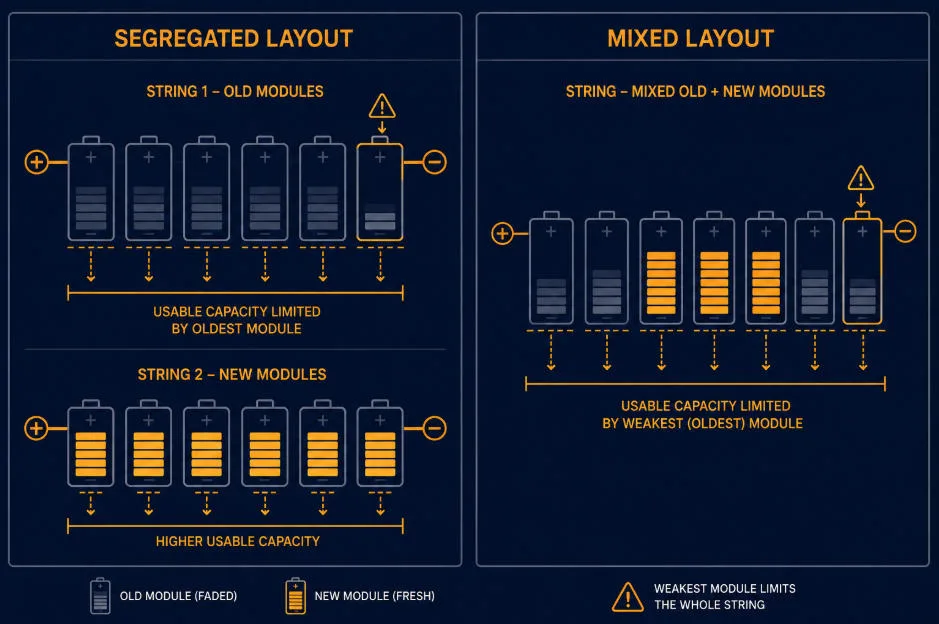
Over time, cells drift apart in State of Charge. The cell with the lowest SOC determines when discharge must stop. Similarly, the cell with the highest SOC determines when charging must stop. If cells are out of balance, the weakest cell constrains the entire pack — even though the others still have capacity.
The BMS corrects this drift through balancing. As a result, all cells stay at the same SOC and the full rated capacity remains usable.
Passive Balancing: Simpler and More Common
Passive balancing is, specifically, the most common approach. The BMS bleeds off excess charge from higher-SOC cells as heat through a resistor. It keeps doing this until, eventually, all cells match the lowest cell.
Advantages: Low cost, simple, reliable, and well-proven across millions of systems.
Disadvantages: Energy is wasted as heat. Balancing current is typically low (20–200 mA), so it is slow. In large packs with heavy imbalance, furthermore, passive balancing cannot keep up.
Passive balancing is, therefore, best suited to residential and small commercial systems. It works particularly well where cell quality is high and cycle frequency is moderate.
Active Balancing: Better for High-Cycle Systems
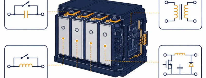
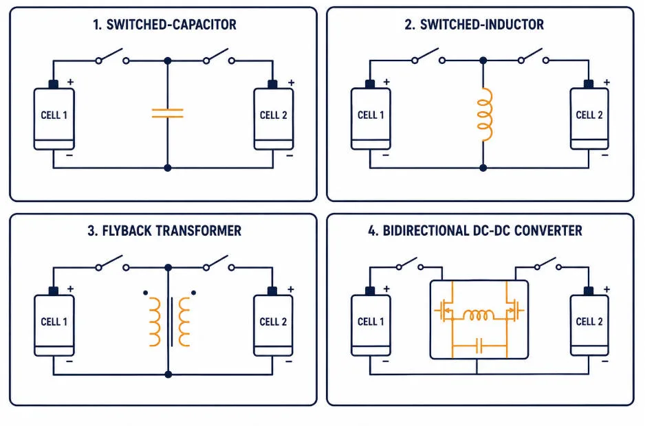
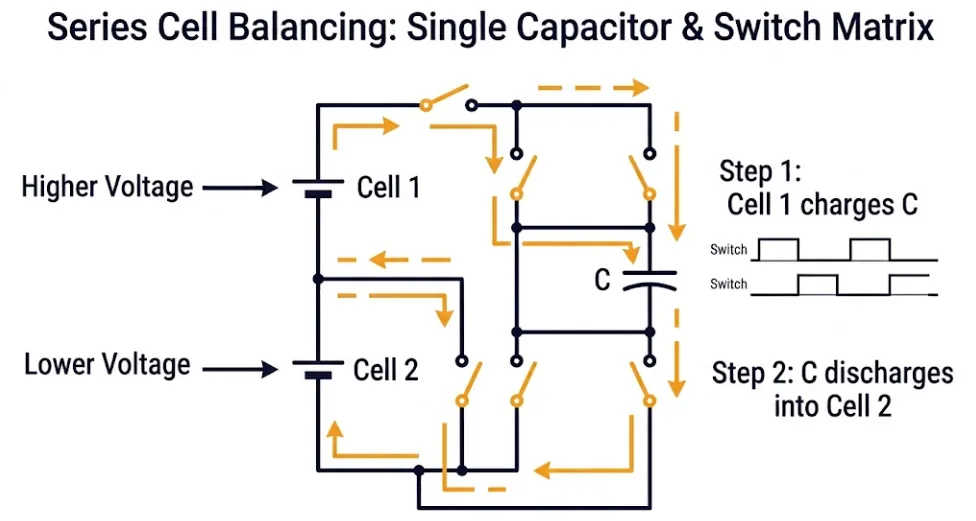
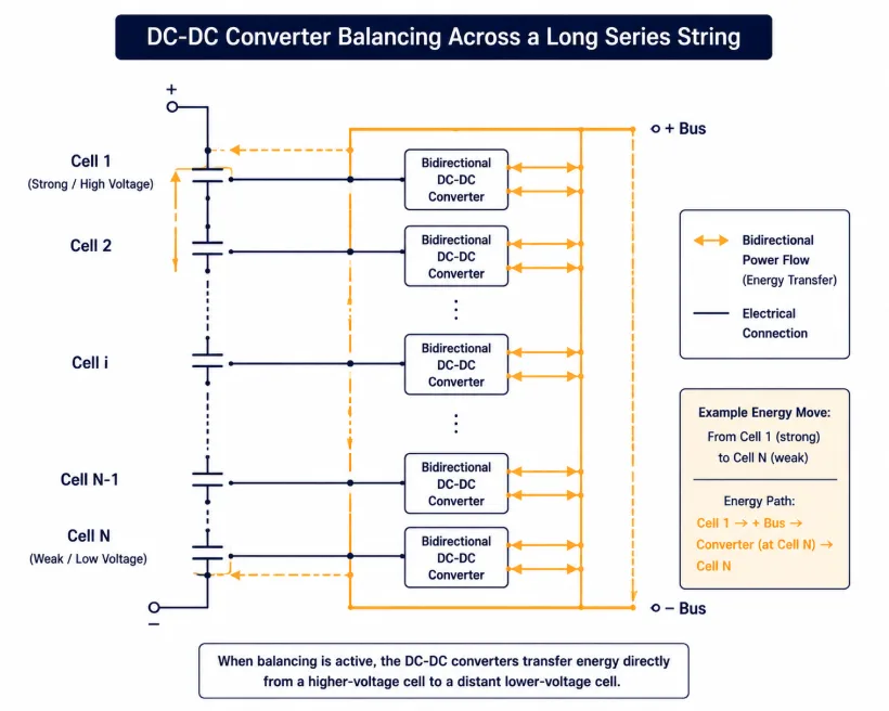
Unlike passive balancing, active balancing transfers energy from higher-SOC cells to lower-SOC cells using inductive or capacitive circuits. Energy is not wasted — instead, it is redistributed within the pack.
Advantages: No energy waste. Higher balancing currents (0.5–5A) mean faster correction. Better long-term capacity retention in high-cycle applications.
Disadvantages: Higher cost and more complexity. There are, therefore, more potential failure points in the balancing circuitry.
Active balancing is, therefore, best specified for utility-scale BESS, frequency regulation, and systems designed for 15+ year lifespans where long-term capacity retention is critical to ROI.
Factor
Passive Balancing
Active Balancing
How it works
Burns excess charge as heat via resistor
Transfers charge between cells electronically
Energy efficiency
Low — energy wasted as heat
High — energy redistributed within pack
Balancing speed
Slow: 20–200 mA typical
Fast: 0.5–5A typical
System complexity
Simple and reliable
More complex, more failure points
Cost
Low
Higher (2–5x passive)
Best for
Residential and small C&I (under 500 kWh)
Utility-scale and high-cycle BESS (over 500 kWh)
5. How the Battery Management System Estimates SOC (State of Charge)
Essentially, SOC is the fuel gauge of your battery. It shows how much energy is stored, expressed as a percentage of full capacity. Accurate SOC is essential for safe operation and efficient dispatch.
Importantly, SOC cannot be measured directly. Instead, it must be estimated from measurable quantities — voltage, current, and temperature. The BMS uses one or more algorithms to do this. Each method has distinct strengths and trade-offs.
Method 1: Open Circuit Voltage (OCV) Lookup
Specifically, this is the simplest SOC estimation method. When a battery has rested for 30–60 minutes, its Open Circuit Voltage maps to SOC via a lookup table. The table is built from cell characterisation tests.
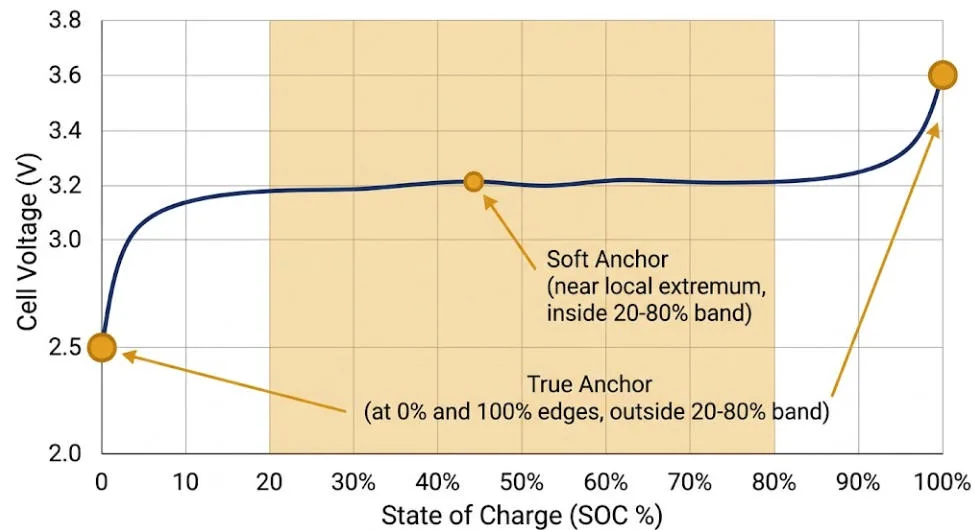
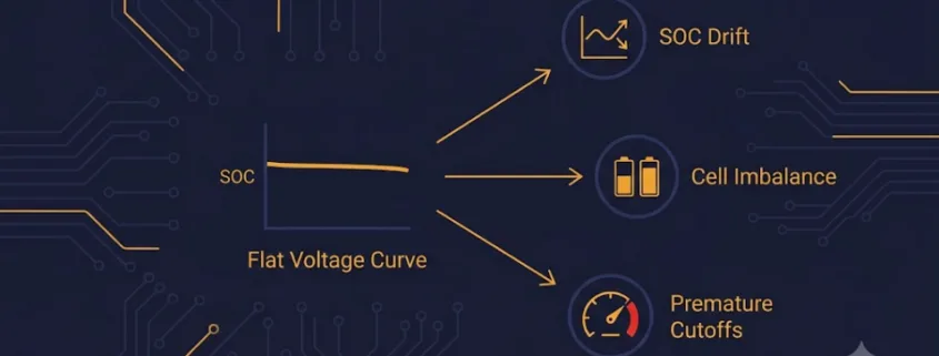
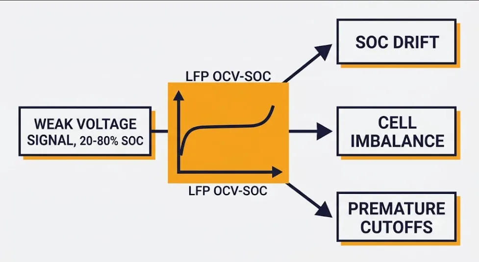
However, OCV works poorly for LiFePO4. LFP has a very flat voltage curve between 20% and 80% SOC. Small voltage changes correspond to large SOC swings in this region. As a result, OCV-based SOC is inaccurate during normal operation. It is mainly useful for setting the initial estimate after a long rest period.
Method 2: Coulomb Counting
Coulomb counting integrates current over time. It tracks how much charge has entered or left the battery. As a result, it is the most widely used SOC method in real-time operation.
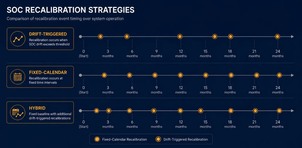
Coulomb counting is accurate over short periods. However, it accumulates error over time due to sensor tolerances, temperature effects, and small unmeasured currents. Without periodic recalibration, the estimate drifts.
Best practice: In practice, reset SOC to 0% or 100% when the battery hits its cutoff voltage. These anchor points correct accumulated drift effectively.
Method 3: Extended Kalman Filter (EKF)
The Extended Kalman Filter is the most accurate SOC method available. It combines Coulomb counting with a mathematical model of the battery’s electrochemical behaviour. Consequently, it corrects the estimate continuously based on the gap between model prediction and actual voltage.
EKF handles LFP’s flat voltage curve far better than OCV. It adapts in real time to temperature changes, aging effects, and varying loads. Furthermore, premium BMS platforms from Texas Instruments, Analog Devices, and Orion BMS use EKF or adaptive Kalman variants.
The trade-off: EKF requires significant processing power and a well-characterised cell model. It is, consequently, computationally demanding and needs careful tuning for each chemistry.
SOC Method
Accuracy
LFP Suitability
Typical Use
Open Circuit Voltage
±5–10% in flat region
Poor — flat curve limits accuracy
Initial SOC after rest period only
Coulomb Counting
±3–5% short term, drifts over time
Good for real-time tracking
Residential and most C&I systems
Extended Kalman Filter
±1–2% with good cell model
Excellent — handles flat curve well
Utility-scale BESS and precision apps
6. How the Battery Management System Tracks SOH (State of Health)
State of Health (SOH) measures how much of a battery’s original capacity remains. A new battery starts at 100% SOH. Each cycle causes a small, permanent capacity loss. Consequently, the BMS tracks this degradation over the system’s lifetime.
Specifically, SOH is defined as: SOH (%) = (Current Capacity ÷ Original Rated Capacity) × 100.
Notably, End of Life (EOL) is declared when SOH drops to 80% — or 70% in some industrial applications. For more on how EOL thresholds work in practice, see our Battery Cycle Standards guide.
How SOH Is Estimated Over Time
SOH cannot be measured with a single reading. Instead, the BMS builds up estimates using several data sources accumulated over time:
Capacity fade tracking — comparing measured full-charge capacity against original rated capacity
Internal resistance measurement — resistance increases as cells age; higher resistance correlates with lower SOH
Cycle counting — simple but imprecise; does not account for partial cycles or varying depth of discharge
Incremental Capacity Analysis (ICA) — an advanced technique that analyses the dV/dQ curve to detect electrochemical aging signatures
SOH Logging and Warranty Compliance
Accurate SOH logging matters for two reasons. First, it supports warranty claims. Most BESS warranties guarantee a minimum SOH at a set cycle count — for example, 80% SOH at 6,000 cycles. The BMS is the primary evidence source for any claim.
Second, SOH logging is becoming a regulatory requirement. The EU Digital Battery Passport, mandatory from February 2027 under EU Batteries Regulation 2023/1542, requires SOH history, cycle count, and energy throughput data. The battery management system is the primary source for all of it.
📊 Battery Management System SOH and Warranty Compliance A BMS that accurately logs SOH over time — with timestamped cycle data — makes warranty claims straightforward. A BMS without proper SOH logging, however, creates disputes. Always ask what SOH data is recorded, how long it is stored, and in what format it can be exported.
7. Battery Management System Requirements: LiFePO4 vs. NMC
LFP and NMC place very different demands on the battery management system — especially for SOC estimation and thermal monitoring speed
LiFePO4 (LFP) and NMC place very different demands on the battery management system. Understanding these differences, therefore, helps you confirm that a supplier’s BMS is genuinely designed for their stated chemistry. A BMS reused from a different application, for instance, will often perform poorly on LFP.
SOC Accuracy: Why LFP and NMC Differ
LFP’s flat voltage curve — discussed in Section 5 — makes SOC measurement significantly harder than NMC. An NMC cell’s voltage, in contrast, changes continuously and predictably with SOC. LFP, however, sits near 3.2V–3.3V across 80% of its SOC range. As a result, OCV lookup is unreliable for LFP in real-time operation.
Consequently, a BMS designed for NMC but deployed on LFP cells will show poor SOC accuracy. This leads to premature shutdowns or unexpected overcharge events. Always, therefore, confirm the BMS SOC algorithm is specifically calibrated for LFP chemistry.
Thermal Monitoring: NMC Is More Demanding
NMC cells are more temperature-sensitive than LFP. Specifically, they degrade significantly above 35°C and have a lower thermal runaway threshold — 150°C to 210°C versus 270°C to 300°C for LFP.
As a result, an NMC battery management system requires:
Temperature monitoring intervals of every 100–500ms — versus every 1–2 seconds for LFP
Faster thermal runaway response — disconnection in milliseconds when temperature spikes
More temperature sensors per module — to catch hot spots before they spread
Integration with active liquid cooling systems — which are common in NMC BESS
NMC cells are damaged more easily by small voltage excursions above the charge cutoff. As a result, a BMS protecting NMC must enforce tighter tolerances — typically ±5mV per cell versus ±10–20mV for LFP. It must also respond faster when a cell approaches its limit.
BMS Function
LiFePO4 (LFP)
NMC
SOC algorithm required
Coulomb counting or Kalman filter essential (flat curve)
OCV lookup or Coulomb counting (clearer voltage slope)
Voltage tolerance per cell
±10–20mV
±5mV — much tighter
Temperature monitoring interval
Every 1–2 seconds typical
Every 100–500ms — faster response needed
Thermal runaway response
Standard — higher threshold
Fast — lower runaway threshold (150–210°C)
Active cooling integration
Optional in most deployments
Often required
Overall BMS complexity
Standard
Higher on all parameters
8. Battery Management System Certifications: Which Standards Apply
As a safety-critical component, the battery management system must, therefore, comply with the relevant standards for each market where the BESS will be installed. Certification covers both the BMS hardware itself and the complete battery system.
Standard
Scope
BMS Relevance
UL 1973
Stationary lithium battery systems
Cell, module, and BMS safety — required for US market access
UL 9540
Complete BESS system safety
BMS must demonstrate system-level protection functions
IEC 62619
Safety for lithium-ion batteries
International standard covering BMS protection requirements
IEC 62933-5
ESS safety framework
Covers BMS communication, monitoring, and fault response
UN 38.3
Transport safety for lithium batteries
BMS must survive vibration, altitude, and thermal tests
EU 2023/1542
EU Batteries Regulation
BMS data required for Digital Battery Passport from 2027
The EU Digital Battery Passport and BMS Data
Specifically, the EU Digital Battery Passport becomes mandatory in February 2027 for industrial and EV batteries above 2 kWh. It is a QR-code record containing a battery’s full lifecycle data — SOH history, cycle count, energy throughput, and temperature exposure.
The battery management system is the primary data source for this passport. Consequently, any BESS sold into the EU after 2027 must have a BMS that records and exports this data in a compliant format. BMS data logging is, therefore, no longer just a technical feature. It is a regulatory requirement. For a full breakdown, see our EU 2023/1542 compliance guide.
9. How to Evaluate a Battery Management System: 8 Questions to Ask
Most buyers evaluate batteries on capacity, cycle life, and price. The BMS is then treated as a given. That is a mistake. These eight questions, therefore, separate a robust battery management system from one that will cause problems in the field.
Questions 1–4: Protection and Accuracy
Question 1: Is cell-level voltage monitoring standard — or only pack-level?
Cell-level monitoring is non-negotiable. A BMS that only monitors overall pack voltage cannot prevent localised overcharge or over-discharge. Always, therefore, confirm cell-level monitoring is standard — not an add-on.
Question 2: What SOC algorithm is used — and is it calibrated for the cell chemistry?
If a supplier cannot answer this clearly, that is a red flag. OCV-based SOC on LFP is inaccurate. Ask whether Coulomb counting, Kalman filtering, or a hybrid method is used. Furthermore, confirm it is tuned for the specific cell chemistry in your system.
Question 3: Is balancing passive or active — and what is the balancing current?
For high-cycle applications or systems above 500 kWh, active balancing is preferable. For smaller residential systems, passive balancing at 100 mA or above is adequate. In contrast, a balancing current under 50 mA in a large pack is a warning sign.
Question 4: How fast does the BMS respond to overcurrent and thermal events?
Short circuit response must be in microseconds. Thermal runaway disconnection must happen in under 100ms. Specifically, ask for the fault response time in the specification — not just a general claim that protection exists.
Questions 5–8: Communication, Data, and Certification
Question 5: What communication protocols are supported?
Confirm the BMS communicates with your inverter and EMS. CAN bus and Modbus RTU are the most common protocols. Additionally, cloud connectivity via MQTT or TCP-IP is increasingly important for monitoring and Battery Passport data exports.
Question 6: Does the BMS log SOH and cycle data — and for how long?
SOH logging is essential for warranty claims and EU Battery Passport compliance. Ask how many years of data is stored, which parameters are logged, and how the data is exported. Consequently, a BMS with no data export capability is a liability for EU market sales after 2027.
Question 7: What happens to cell protection if the master controller fails?
In a master-slave BMS, slave modules must maintain cell-level protection independently — even without master communication. A system where protection depends entirely on the master creates a single point of failure. Therefore, always ask this question before signing.
Question 8: Which certifications does the BMS hold — and can you provide test reports?
UL 1973, IEC 62619, and IEC 62933-5 are the key standards. A reputable supplier provides full test documentation — not just a certificate summary. If they hesitate, that is therefore a red flag.
10. Battery Management System Failure Modes: What Goes Wrong
Common battery management system failure modes and how to prevent each one in a BESS installation
Understanding how a battery management system can fail helps you design systems with the right redundancy. It also helps you evaluate suppliers whose BMS architecture accounts for these risks.
Failure Mode
Consequence
Prevention
Voltage sensor drift
Incorrect SOC — risk of overcharge or over-discharge
Dual redundant sensors; periodic recalibration against known references
Temperature sensor failure
Missed thermal event — possible thermal runaway
Multiple sensors per module; cross-validation between sensors
Balancing circuit failure
Cell imbalance grows; usable capacity shrinks
Active monitoring of balancing currents; SOC spread alerts
Master-slave communication loss
Master loses visibility of module status
Slaves maintain local protection; heartbeat watchdog triggers alarm
Contactor weld failure
BMS cannot disconnect pack during a fault
Pre-charge circuits; contactor health monitoring; dual contactors on large systems
OTA firmware updates; staged rollouts; version logging with rollback capability
11. The Battery Management System in a Complete BESS: System Integration
Importantly, the battery management system does not operate in isolation. In a complete BESS, it sits at the centre of a data and control network — connecting cells to the inverter, the EMS, the monitoring platform, and the thermal management system.
Connecting to the Inverter
The BMS sends SOC, available power, voltage, and fault status to the inverter in real time. The inverter uses this data to manage charge and discharge rates and respect SOC limits. It also triggers a soft shutdown when the battery approaches empty.
Without reliable BMS-to-inverter communication, the inverter operates blind. As a result, overcharge or deep discharge events become possible.
Connecting to the Energy Management System (EMS)
The EMS sits above the BMS in the control hierarchy. It uses BMS data to decide when to charge, when to discharge, and how much power to commit to a grid services contract. Consequently, a BMS that cannot communicate reliably with the EMS limits the system’s ability to optimise for economics.
To understand how BESS economics work in practice, see our guide on calculating BESS ROI.
Connecting to Remote Monitoring Platforms
Cloud-connected monitoring platforms use BMS data to track performance and flag early warnings. Typical parameters include SOC, SOH, cell voltage spread, temperatures, energy throughput, and fault logs. Moreover, this data is increasingly required for EU Battery Passport compliance after 2027.
Connecting to Thermal Management Systems
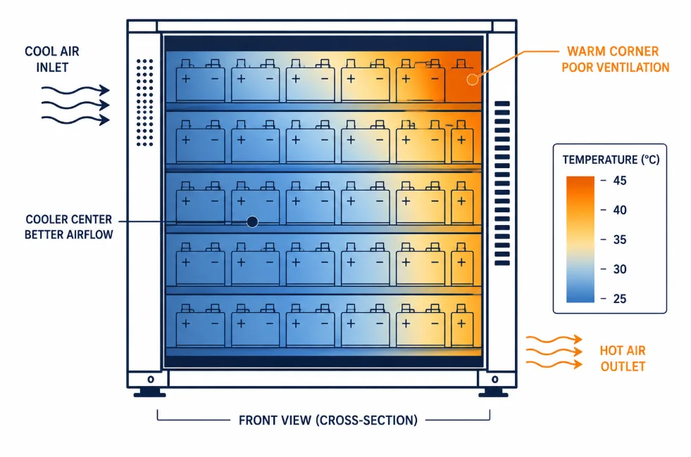
In systems with active cooling — fans or liquid cooling — the BMS directly controls the thermal hardware. It turns cooling on and off based on real-time cell temperature readings. In liquid-cooled NMC systems, this link is especially critical. In LFP systems, thermal management is simpler — but still important in warm climates or poorly ventilated enclosures.
Conclusion: The Battery Management System Is Not a Commodity
The battery management system determines whether a BESS is safe. It also determines whether cells reach their rated cycle life — and whether capacity is fully used. It is, therefore, not a component to be cut from the bill of materials.
Here are the key takeaways from this guide:
Cell-level voltage and temperature monitoring are non-negotiable in any lithium system
SOC algorithm choice matters enormously — especially for LFP’s flat voltage curve
Balancing method should match your cycle frequency and system size
SOH logging is now a regulatory requirement under the EU Battery Passport — not just a technical feature
BMS architecture must scale with system size: single-level for residential, master-slave for commercial and utility
Use the eight evaluation questions above before accepting any supplier’s BMS specification
Overall, whether you are designing a 10 kWh home system or a 10 MWh grid-scale BESS, the battery management system deserves the same scrutiny as the cells. A good BMS extends the life of average cells. A poor BMS, in contrast, shortens the life of great ones.
☀️ Need a Battery Management System Review for Your BESS Project? Sunlith Energy reviews BMS specifications and supplier documentation for BESS projects from 50 kWh upward. Specifically, we identify gaps in protection architecture, SOC algorithm suitability, and certification compliance — before you sign a purchase order. Contact us
Frequently Asked Questions About the Battery Management System
Does a LiFePO4 battery need a BMS?
Yes — without exception. LiFePO4 is chemically stable, but it still needs a battery management system. Specifically, the BMS prevents overcharge, over-discharge, short circuit, and thermal damage. No reputable BESS supplier ships lithium cells without one.
What is the difference between a BMS and a battery controller?
The battery management system monitors and protects individual cells and modules. A battery controller — or Master BMS — manages the full system and coordinates with the inverter and EMS. In simple residential systems, one device does both. In large commercial systems, however, they are typically separate hardware.
Can a BMS extend battery life?
Yes — significantly. A BMS keeps cells within safe voltage and temperature limits. It also maintains good cell balance and enforces appropriate C-rate limits. As a result, it extends cell life considerably compared to unprotected operation.
This depends on your inverter and EMS. CAN bus is most common in high-performance systems. Modbus RTU over RS485, however, is standard in commercial and industrial storage. Check your inverter’s compatibility list first — mismatched protocols require additional gateway hardware and add cost and complexity.
How do I know if my BMS is failing?
Watch for these warning signs: SOC readings that jump unexpectedly; growing cell voltage spread, which indicates poor balancing; shutdowns not caused by actual low SOC; temperature readings that are static or incorrect; and fault codes that repeat in the log without a clear cause. In particular, growing cell voltage spread is often the earliest signal of BMS trouble.
Remote monitoring platforms are, therefore, the most reliable early detection tool. They flag SOC spread and temperature anomalies before they become failures.
In the age of electric vehicles, solar energy storage, and portable power, batteries are everywhere. However, they don’t work efficiently—or safely—on their own. That’s where the Battery Management System (BMS) steps in.
A BMS monitors, protects, and optimizes battery operation. In this guide, we’ll break down how a BMS works, what makes it essential, and how it improves battery safety and performance.
Let’s begin with the basics.
🔍 What Is a BMS (Battery Management System)?
A Battery Management System (BMS) is an electronic controller found in nearly every advanced battery pack. Whether in electric scooters or solar home systems, the BMS performs several important tasks:
It monitors battery health and performance.
It protects the battery from unsafe conditions.
It balances cells to maintain consistency.
It calculates key values like State of Charge (SOC) and State of Health (SOH).
It communicates with other devices and controllers.
In short, it acts as the brain behind the battery.
Each battery cell has a safe voltage range. The BMS monitors individual cell voltages and the total pack voltage. Even a small voltage imbalance can reduce performance or cause damage.
➡️ Why it matters: It helps avoid overcharging or over-discharging, which can permanently damage cells.
⚡ Current Monitoring
By measuring the charging and discharging current, the BMS keeps track of how much energy is moving in or out of the battery.
➡️ Why it matters: It prevents dangerous current spikes and helps calculate the battery’s remaining energy.
🌡️ Temperature Monitoring
Battery temperature is closely watched using thermal sensors. Too much heat or cold can cause big problems.
➡️ Why it matters: If a battery gets too hot, it can overheat or even catch fire. Monitoring temperature helps avoid this.
🛡️ BMS Protection Features: Preventing Damage Before It Happens
Real-time monitoring is helpful, but monitoring alone isn’t enough. The BMS also responds when things go wrong. It includes four core protection mechanisms, each with a specific safety role.
1. ✅ Over Voltage Protection (OVP)
If a battery is charged beyond its safe limit, chemical reactions inside the cells can become unstable.
➡️ Why it matters: OVP prevents this by stopping charging when voltage gets too high. This protects the cells and keeps them from overheating.
2. ❌ Under Voltage Protection (UVP)
If voltage drops too low during discharge, cells can be permanently damaged.
➡️ Why it matters: UVP shuts down the battery before damage occurs. It helps protect capacity and extends battery life.
3. 🌡️ Over Temperature Protection (OTP)
Charging or discharging at extreme temperatures can harm the battery.
➡️ Why it matters: OTP stops activity when the battery is too hot or cold. This ensures safe operation in every condition.
4. ⚠️ Short Circuit Protection (SCP)
If a short circuit occurs, current can spike instantly. This can lead to fire or explosion.
➡️ Why it matters: SCP reacts in microseconds to cut off power, preventing serious accidents.
⛽️ State of Charge (SOC): How Much Energy Is Left?
Think of SOC as the battery’s fuel gauge. It tells you how much usable energy remains, usually shown as a percentage (like 75% or 50%).
How SOC is calculated:
Coulomb counting: Tracks how much current flows in and out.
Voltage-based estimation: Uses resting voltage as an indicator.
Temperature-corrected models: Account for heat effects on performance.
➡️ Why it matters: Knowing SOC helps you avoid running out of battery unexpectedly. It also prevents overcharging, which protects the battery.
➡️ Why it matters: A battery may charge fully but still not perform like new. SOH lets users know when a battery is aging or needs replacement. It’s also useful for warranties and service checks.
⚖️ Cell Balancing: Keeping Every Cell in Sync
While monitoring and protection are essential, a truly effective Battery Management System also performs cell balancing. This function ensures that all individual cells within the battery pack maintain equal voltage levels.
Over time, slight differences in cell chemistry, resistance, or temperature cause some cells to charge faster or slower than others. Left unchecked, this leads to performance drops and early aging.
📌 What Is Cell Balancing?
Cell balancing equalizes the voltage of each cell, improving pack efficiency and lifespan.
There are two main types:
1. 🔋 Passive Balancing
In passive balancing, extra energy from higher-voltage cells is burned off as heat using resistors.
✅ Simple and low-cost
✅ Common in consumer electronics
❌ Less efficient due to energy loss
2. ⚡ Active Balancing
Active balancing redistributes charge from more charged cells to less charged ones, using inductors, capacitors, or switch networks.
✅ Higher efficiency
✅ Extends battery life
✅ Suitable for EVs, BESS, drones
❌ More complex and expensive
🧠 Why Balancing Matters
Balancing is critical because even small voltage mismatches between cells can lead to:
Uneven charging
Reduced usable capacity
Early triggering of safety cutoffs
Accelerated aging in weaker cells
By balancing cells, the BMS ensures every cell contributes equally—maximizing safety, performance, and battery lifespan.
⚙️ Where BMS Is Used
You’ll find BMS systems in many places, including:
…a BMS ensures that the battery stays safe, efficient, and long-lasting.
If you’re using or building battery-powered systems, never ignore the importance of a well-designed BMS. It’s the hidden engine behind every reliable energy solution.
🤛 BMS Frequently Asked Questions
Q1: Can I use batteries without a BMS?
➡️ Technically yes, but it’s risky. A BMS prevents overheating, damage, and accidents.
Q2: What type of batteries use a BMS?
➡️ Mostly lithium-based batteries (like Li-ion or LiFePO4), but other chemistries can also benefit.
Q3: Can a BMS extend battery life?
➡️ Absolutely. By balancing cells, protecting from damage, and avoiding extreme conditions, a BMS helps batteries last longer.
Q4: How accurate is the SOC reading?
➡️ Accuracy depends on the BMS algorithm, temperature conditions, and battery type. Premium systems can be highly precise.
In today’s world of renewable energy and smart grids, understanding the key components in a BESS architecture is very important. A Battery Energy Storage System (BESS) is made up of several parts that work together to store, manage, and deliver electricity safely and efficiently. In this blog post, we’ll break down each major component — what it does and why it matters — so you can see how a BESS works as a whole.
What Is a BESS?
Before we dive into the key components in a BESS architecture, let’s quickly explain what a BESS is. A Battery Energy Storage System is a setup that stores electricity in batteries so it can be used later. It helps balance energy supply and demand, provides backup power, and supports the use of renewable energy like solar and wind.
1. Battery Packs: The Core Energy Storage Units
The battery packs are the heart of any BESS. These packs are made up of many individual battery cells grouped together. They store the electrical energy until it’s needed.
Function: Store electrical energy in chemical form and release it as needed.
Why It Matters: The quality and type of battery pack (like Lithium-ion, LFP, or others) decide how much energy you can store, how long it lasts, and how safe the system is.
Tip: Always choose battery packs from reputable manufacturers with proper certifications.
2. Battery Management System (BMS): Monitors and Protects
The Battery Management System (BMS) is like the brain for the battery packs. It constantly checks the status of each cell to make sure everything works safely.
Function: Monitors voltage, temperature, and charge level. Balances cells and protects against overcharging or deep discharge.
Why It Matters: Without a good BMS, batteries can get damaged, lose efficiency, or even pose safety risks.
Tip: A well-designed BMS extends battery life and helps you get the most from your investment.
3. Power Conversion System (PCS): Converts Power
The Power Conversion System (PCS) is what makes your stored energy usable. Batteries store electricity as Direct Current (DC), but most homes and businesses use Alternating Current (AC).
Why It Matters: A good PCS maximizes efficiency, ensures stable power output, and protects connected devices.
Tip: Look for PCS units with high conversion efficiency and reliable grid interaction features.
4. Energy Management System (EMS): Controls Energy Flow
The Energy Management System (EMS) decides when to charge, when to discharge, and how to manage energy flows smartly.
Function: Monitors energy demand, renewable production, and market conditions to optimize usage.
Why It Matters: An EMS helps reduce electricity bills, maximize renewable energy use, and maintain grid stability.
Tip: Modern EMS can be cloud-based, allowing remote monitoring and control for better energy savings.
5. Cooling and Safety Systems: Keep It Safe and Efficient
Batteries generate heat during charging and discharging. That’s why Cooling and Safety Systems are vital parts of any BESS architecture.
Function: Maintain safe operating temperatures, prevent overheating, and manage emergencies like fires.
Why It Matters: Proper thermal management improves battery life and reduces safety risks.
Tip: Systems can use air cooling, liquid cooling, or a mix. Always ensure your system meets local safety standards.
Why Knowing These Key Components in a BESS Architecture Matters
Understanding the key components in a BESS architecture helps you make better decisions when planning or buying a system. Each part plays a role in safety, efficiency, and cost-effectiveness.
When all these components work together, you get reliable energy storage that supports your home, business, or grid.
Frequently Asked Questions (FAQ)
Q1: Which component is the most important in a BESS?
A: All components are important, but the battery packs and BMS are the core for safety and performance.
Q2: Can I upgrade one part of my BESS later?
A: It depends. Some parts like EMS software can be upgraded, but battery packs or PCS upgrades need expert checks for compatibility.
Q3: How do I maintain a BESS?
A: Regular checks on the BMS, PCS, cooling system, and software updates are recommended to keep your BESS in top shape.
Final Thoughts
Knowing the key components in a BESS architecture is the first step to using battery storage wisely. Whether you’re planning a home energy system or a big grid-scale project, make sure you work with trusted suppliers and ask about certifications, maintenance, and upgrades.