
Cold-Climate BESS Design: Discharge-Side DCIR and Premature Cutoffs
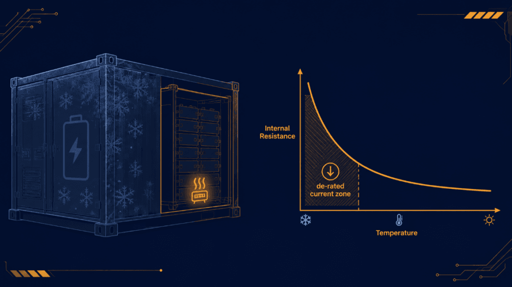
Most cold-weather BESS design attention goes to charging. Lithium plating below roughly 0°C is a real, well-documented risk. Charge-inhibit logic is standard practice for good reason. Discharge-side cold behavior gets far less coverage. But it drives a different problem: resistance-driven voltage sag that trips a cutoff long before the pack is actually empty. This guide covers cold-climate BESS design for the discharge side specifically. It covers how cold amplifies the same DCIR mechanism covered in our dynamic cutoff design guide. It also covers what that means for current de-rating, heater sizing, and enclosure insulation.
| ⚡ Quick Answer Cold-climate BESS design has to account for LFP internal resistance rising sharply as temperature drops, since ion mobility slows in the electrolyte and at the electrode interface. This increases voltage sag under load, which can trip a fixed or even a DCIR-adaptive cutoff early if the resistance lookup table doesn’t extend to true cold-climate minimums. The design response has three parts: extending the cutoff’s temperature matrix to cover real winter conditions, applying current de-rating as temperature drops, and sizing enclosure heating and insulation to keep cells out of the steepest part of the resistance curve. |
Why Cold-Climate BESS Design Needs to Address Discharge-Side DCIR
Our DCIR-adaptive cutoff design guide covers how internal resistance rises with cell age. It also covers how a fixed cutoff voltage fails to account for that rise. Cold temperature drives the same mechanism through a different cause. As temperature drops, electrolyte viscosity increases and ionic mobility slows, both in the bulk electrolyte and at the electrode interface. That raises internal resistance independent of cell age or cycle count. A fresh cell at -10°C can show meaningfully higher resistance than an aged cell at 25°C.
The practical effect is the same voltage-sag mechanism covered in the cutoff design guide.
Vterminal = VOCV − I × DCIR
A higher DCIR term means more sag at identical current, which reaches a fixed trip voltage sooner. This isn’t a marginal effect. A coupled electrochemical-thermal model validated against real cells from -20°C to 45°C confirms resistance rises sharply as temperature drops. Usable discharge capacity falls well below nameplate rating in the -10°C to -20°C range. That drop is driven primarily by the resistance rise, not by any real loss of stored charge. The energy is still in the cell. The pack just can’t deliver it fast enough to clear the cutoff threshold at typical discharge rates.
This matters most for anyone who has already implemented a DCIR-adaptive cutoff per our earlier guide. Say the HPPC test matrix behind that lookup table stopped at a moderate low-temperature bound, rather than the site’s true winter minimum. In that case, the adaptive cutoff extrapolates poorly. It can even fail safe into overly conservative behavior — exactly in the conditions where it matters most.
Extending the Cutoff Matrix for Cold-Climate BESS Design
The fix is directly upstream of implementation, not a separate system. The HPPC test campaign behind a DCIR-adaptive cutoff needs a temperature range that matches real deployment conditions. It shouldn’t just reflect a generic qualification range. A system specified for a temperate climate, but deployed somewhere with regular sub-zero winter lows, needs its lookup table re-tested. It needs to be rebuilt for that colder range. That should happen before commissioning, not patched in after a field failure.
Two practical points from that testing process carry directly into cold-climate design:
- Pulse-test resistance at temperature steps that bracket the real minimum with margin, not just the design spec’s stated floor. Local weather can exceed nameplate assumptions during extreme events.
- Re-validate hysteresis settings at cold temperature specifically. A cutoff tuned for hysteresis behavior at room temperature can behave differently at the steeper part of the resistance curve. There, small current fluctuations produce larger voltage swings.
Current De-Rating Strategy for Cold-Climate BESS Design
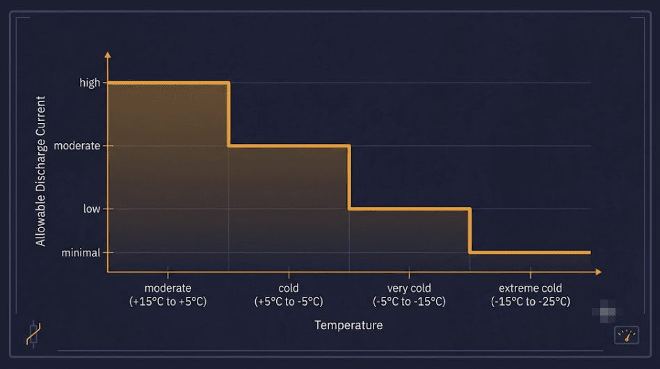
Even with an accurate cold-temperature resistance map, discharging at full rated current in cold conditions is risky. It pushes the system into the steepest part of the resistance curve. That’s where voltage sag grows fastest per unit of additional current. Current de-rating reduces the maximum allowed discharge current as measured cell temperature falls. It keeps the operating point away from that steep region. That’s safer than relying on cutoff logic alone to catch the problem after the fact.
A practical de-rating curve ties allowable current to the same temperature bands used in the DCIR lookup table. It steps down current limits at each band, rather than applying one blanket reduction across the entire cold range. This preserves as much usable power as safely possible at moderately cool temperatures. It pulls back harder as conditions approach the pack’s true low-temperature floor.
Heater Sizing for Enclosure Thermal Management
Where current de-rating manages the symptom, enclosure heating addresses the cause. It keeps cells out of the steep-resistance temperature range in the first place. A Sandia-led modeling study across eight U.S. locations found that enclosure heating and cooling loads alone increased required battery energy capacity. The increase ranged from 42% to 300%, depending on climate severity. The same study found that power conversion system placement matters too. Keeping the PCS inside the thermally managed envelope reduced the capacity penalty; leaving it exposed outside increased it. That model was built around an NMC cell, not LFP. LFP chemistry is generally more resistance-sensitive in cold conditions. So the real capacity penalty for an LFP system is likely at or above this range, not below it.
Heater sizing follows standard enclosure thermal design practice. Calculate steady-state heat loss for the enclosure’s surface area and target ΔT. Then apply a safety margin, commonly in the 125–130% range. That covers thermal mass and startup transients, not just steady-state loss. Insulation quality changes this calculation substantially. A well-insulated enclosure can cut steady-state heat loss by roughly 90% compared to an equivalent bare-metal enclosure. That’s normally the larger lever before reaching for a bigger heater.
Insulation and Enclosure Strategy in Cold-Climate BESS Design
BESS enclosures almost always use sealed-loop climate control rather than direct outside-air ventilation. Pulling ambient air through the battery compartment introduces humidity, salt, and dust. Those contaminants degrade cells and can create insulation-resistance faults over time. A cold-climate site often adds condensation risk too, from indoor-outdoor temperature swings. The standard architectures are a split air-conditioning unit with a sealed evaporator inside the compartment, for small to mid-size systems. Larger systems, above roughly 1 MWh or with high C-rate demands, typically use liquid cooling with cold plates instead. Whichever architecture is used, insulation determines how hard the heater has to work. It’s what holds the compartment above the steep-resistance zone, making it a critical factor in overall cold-climate BESS design. That’s worth specifying to the actual climate data for the site, not a generic regional assumption.
Bringing It Back to the Cutoff and Estimation Layers
Cold-climate design doesn’t introduce a new subsystem. It extends the temperature range that two subsystems already covered in this series need to handle correctly. The DCIR-adaptive cutoff’s lookup table needs a temperature axis that reaches the site’s true minimum. An EKF-based SOC estimator built from the same HPPC campaign needs its equivalent circuit model fitted across that same cold-temperature range. A model that only saw moderate temperatures during characterization will estimate poorly outside that range. Our EKF SOC estimation design guide and DCIR-adaptive cutoff design guide both assume the underlying test matrix covers real operating conditions. Cold-climate deployment is where that assumption needs the most scrutiny.
Key Takeaways
Cold-climate BESS design starts with the same electrolyte-viscosity and ion-mobility mechanisms that raise LFP internal resistance with age. That resistance rise produces the same voltage-sag effect that drives premature cutoffs. A DCIR-adaptive cutoff only protects against this if its HPPC test matrix extends to the site’s real winter minimum. A generic qualification range isn’t enough. Current de-rating tied to temperature bands keeps the operating point out of the steepest part of the resistance curve. That’s safer than relying on cutoff logic alone. Enclosure heater sizing should follow standard steady-state-plus-safety-margin methodology, with insulation quality as the larger lever before increasing heater capacity. Cold-climate design extends the same estimation and cutoff systems covered elsewhere in this series, rather than requiring a separate architecture.
Frequently Asked Questions
Does a DCIR-adaptive cutoff automatically handle cold-climate conditions?
Only if the HPPC test matrix used to build its lookup table extends to the site’s real winter minimum temperature. A table built against a generic or moderate qualification range will extrapolate poorly at true cold-climate lows. That can produce either an unsafe cutoff or an overly conservative one.
Is current de-rating necessary if the enclosure is heated?
Even a well-heated enclosure has a startup period. It can also see localized cold spots before reaching steady state. Current de-rating remains a useful safeguard during that transition. It’s not made redundant by heating alone.
How much does insulation actually reduce heater size?
A well-insulated enclosure can cut steady-state heat loss by roughly 90% compared to an equivalent bare-metal enclosure. That’s typically a larger lever than increasing heater wattage on a poorly insulated design.
References
Ji, Zhang, Wang — “Li-Ion Cell Operation at Low Temperatures,” Journal of The Electrochemical Society (2013)
Sandia National Laboratories / Energy journal — Impact of Heating and Cooling Loads on Battery Energy Storage System Sizing in Extreme Cold Climates
Further Reading
Dynamic, DCIR-Adaptive Voltage Cutoff Design for LFP BESS
EKF SOC Estimation Design for LFP BESS
Designing an LFP BESS Against SOC Drift, Cell Imbalance, and Premature Cutoffs







Trackbacks & Pingbacks
[…] Cold-Climate BESS Design: Discharge-Side DCIR and Premature Cutoffs […]
[…] section covers the general heat effect. If you run a system in a cold climate, our guide on Cold-Climate BESS Design covers cutoff behavior in full detail. For the underlying temperature/cycle-life relationship, see […]
Leave a Reply
Want to join the discussion?Feel free to contribute!