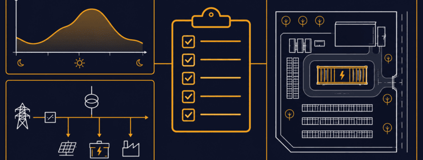
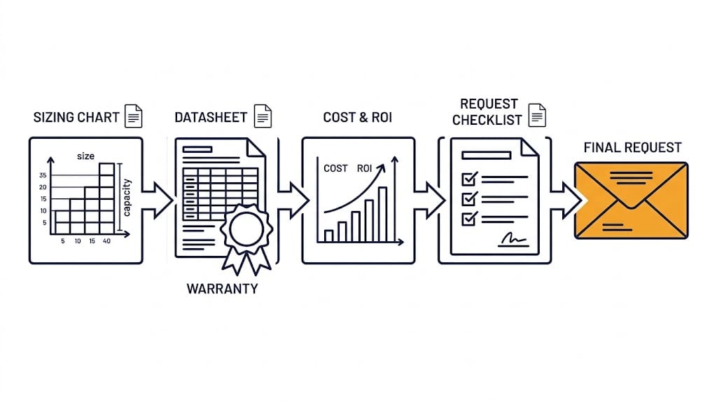
A C&I BESS quote is only as useful as the information behind it. In fact, a one-line request rarely supports reliable sizing or a comparable installed-price estimate.
Send your load data, tariff details, site facts, and main goal up front. Then every bidder answers the same question.
This guide covers the data, documents, and questions to prepare. Finally, it offers a request email you can copy and send.
Quick Answer: To request a C&I BESS quote, state your application, site location, target operating date, and available electrical and space details. Next, add interval load data and the tariff for savings-based projects, or critical loads and backup duration for resilience. Finally, share a single-line diagram if you have one.
Why a Generic C&I BESS Quote Is Not Enough
Asking what a 1 MWh system costs does not produce a project-ready C&I BESS quote. That is because installed cost depends on far more than battery size.
Energy duration and power rating
The application the battery must serve
Interconnection and controls
Site civil work and safety systems
Commissioning and warranty requirements
Each item changes the price. So a bare price request tells a supplier very little.
Quote preparation brings together the application, preliminary sizing, specifications, warranty requirements, and economic assumptions. However, you can refine these inputs with the supplier as the project develops.
Start Your C&I BESS Quote With the Application
Every C&I BESS quote starts with the job the battery must do. Because each job needs different data, the table below separates them.
If you have more than one goal, rank them. Otherwise, a system tuned for one job may perform poorly at another.
Prepare the Data Behind Your C&I BESS Quote
Three groups of information shape every C&I BESS quote request. Since each group answers a different supplier question, gather all three.
Energy and Tariff Information
For peak shaving and tariff-based savings analysis, aim for at least 12 consecutive months of interval data where available.
Use the utility’s demand-measurement interval, or finer data that can be aggregated to it. Also state the timestamps, time zone, units, and whether each reading is average kW or interval kWh.
Current utility bills
The full tariff or rate schedule
Demand charges, time-of-use windows, ratchets, and export compensation rules
Existing and planned solar generation data
Electrical and Site Information
Facility location and utility
Main-service voltage, transformer rating, and available capacity
Single-line diagram, where available
Existing switchgear, protection equipment, generator, and solar-inverter details
Proposed point of interconnection
Site plan, access route, usable footprint, setbacks, and fire-access constraints
Operational and Commercial Information
Main BESS use case and priority order
Target kW reduction, backup duration, or EV-charging demand
Typical operating schedule and seasonal changes
Expansion plans
Desired commercial-operation date
Budget range, procurement route, and financing preference, if you are willing to share them
Missing a document? Send what you have. Then the supplier can list the gaps and request the rest later.
What Suppliers Should Include in Their Reply
A budgetary estimate may give an indicative configuration, price range, scope, and assumptions without detailed engineering. In contrast, a developed proposal should add a more defined layout, electrical interface, commissioning scope, and itemized exclusions.
State which stage you are requesting. Also ask suppliers to flag anything that still depends on site investigation or engineering.
A strong C&I BESS quote does more than state a price. Next, ask each bidder to cover these items.
Proposed AC power rating, usable energy, and nominal energy
Stated duration at rated power
Assumed measurement boundary for capacity and efficiency
Scope of PCS, battery, BMS, EMS, HVAC, fire-safety, enclosure, and balance-of-system equipment
Interconnection and site-work assumptions
Conceptual layout and electrical-interface information, where available; more detailed drawings at the developed-proposal stage
Performance assumptions and dispatch limitations
Warranty scope, capacity retention, throughput limit, exclusions, and remedies
CAPEX breakdown, exclusions, O&M scope, and optional services
Schedule, commissioning plan, and commercial assumptions
Quote validity, currency, delivery basis, taxes or duties, payment milestones, and major price-adjustment conditions
Because unclear terms make bids hard to compare, read SunLith’s guide to understanding BESS specifications. It explains how vendors define capacity, power, and efficiency.
Also ask how the supplier plans for capacity loss over time. Our guide to BESS augmentation planning covers that topic.
Questions to Compare Across Every C&I BESS Quote
Use these questions to put every C&I BESS quote on the same footing. Ask for written answers as well, and have important assumptions, inclusions, and exclusions written into the proposal.
Capacity and Performance Questions
Is the energy rating nominal, usable DC, AC delivered, or measured at the point of interconnection?
What duration does the system provide at rated power?
Does the proposal assume one application or stacked value streams?
How are HVAC and auxiliary loads counted in efficiency and available-energy assumptions?
Scope and Ownership Questions
Which site upgrades, civil works, interconnection studies, permits, or fire-protection measures are excluded?
Who owns the EMS controls, performance monitoring, and data access?
What do commissioning, acceptance testing, training, remote monitoring, and maintenance include?
Warranty and Lifecycle Questions
Which warranty limits apply to DoD, throughput, C-rate, SOC, temperature, and dispatch?
What annual O&M and replacement costs are assumed?
What must happen for capacity augmentation, and who pays for it?
Because C-rate limits often sit inside warranty terms, see BESS C-rate explained for how those limits work.
Common Mistakes When Requesting a Quote
These errors often weaken a C&I BESS quote request. If you avoid them, your bids will be easier to compare.
Requesting price without an application: As a result, the supplier must make assumptions about the required kW, kWh, and controls.
Sharing one monthly utility bill: Because it hides peak shape, duration, and seasonal change, sizing stays uncertain.
Comparing nominal kWh with usable AC energy: Since the two numbers measure different things, the bids will not match.
Ignoring tariff and demand-charge rules: When you miss them, the value of every kW you cut is unclear.
Assuming extras are included: Unless stated, PCS, HVAC, fire protection, controls, and civil work may sit outside the price.
Comparing warranty years alone: Instead, check throughput and operating limits as well as the term.
Asking for a system sized for savings: Without sufficient load, tariff, and site information, savings-based sizing remains speculative.
Copy-and-Paste RFQ Email Template
Use this template to start your C&I BESS quote request. Replace each bracketed item with your own details before sending.
Subject: Request for preliminary C&I BESS assessment and budgetary quote
We are evaluating a battery energy storage system for [facility type] at [location]. Our primary objective is [peak shaving / backup / solar self-consumption / EV charging / other].
Attached are [interval load data / utility bills / tariff / single-line diagram / site plan].
Please provide a preliminary recommendation. Include proposed AC power, usable energy, expected duration, and key assumptions.
Also include required site or interconnection work, budgetary CAPEX, warranty summary, delivery schedule, and information needed for a detailed proposal.
Our target decision date is [date], and our target commercial-operation date is [date].
Send it to more than one supplier. Also use the same attachments each time.
Frequently Asked Questions About a C&I BESS Quote
When buyers prepare a C&I BESS quote request, the same questions come up often.
What data do I need for a C&I BESS quote?
Start with your application, site location, available electrical information, and target operating date. For peak shaving or tariff-based savings, include interval load data and the utility tariff.
For backup, provide critical-load requirements and the required backup duration. In addition, a single-line diagram and site plan help refine the proposal where available.
Can I get a C&I BESS quote with only one utility bill?
You may receive a budgetary estimate, but its sizing and savings assumptions will be limited. That is because one bill hides peak shape and seasonal change. Instead, interval data gives a far better basis.
Why do C&I BESS quotes differ so much?
Bids often use different definitions and scope. For example, one may quote nominal energy and another usable AC energy. Therefore, ask every bidder to state its assumptions.
Do I need a single-line diagram before I ask?
It helps, but it is not always required. If you lack one, send equipment nameplate details and photos of the main switchgear. As a result, the supplier can request more later.
Is a preliminary assessment the same as a final proposal?
No. A preliminary assessment gives budgetary figures and stated assumptions. However, a detailed proposal needs site-specific electrical, tariff, interconnection, and safety review.
Ready to Request a Preliminary Assessment?
Contact SunLith for a C&I BESS quote with your project objective, site location, and available load, tariff, and electrical information. If documents are missing, explain what you have so we can identify the next steps.
A C&I BESS sizing calculator answers one question fast. How big should the battery and inverter be?
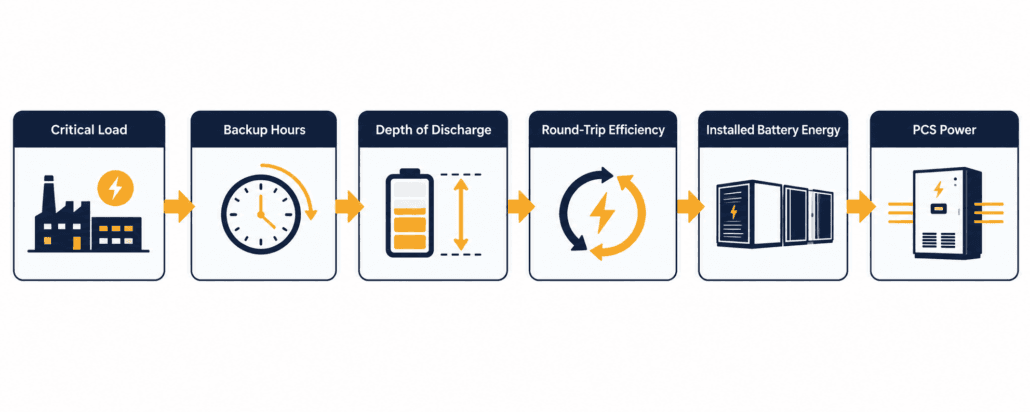
It turns your critical load and backup hours into two numbers. First, installed battery energy in kWh. Second, PCS power in kW.
Use the free calculator below for a preliminary estimate. Then review the formulas, assumptions, and worked example before making project decisions.
Quick Answer: A C&I BESS sizing calculator turns your critical load and backup hours into two numbers. Installed battery energy in kWh factors in depth of discharge and round-trip efficiency. PCS power in kW adds a safety margin to your critical load. Still, this is a preliminary size, not a final design.
Try the C&I BESS Sizing Calculator
This calculator runs instantly in your browser. Once you enter a few numbers, it returns a preliminary size.
Enter your peak site load, critical load, and backup duration below. Then adjust depth of discharge, round-trip efficiency, and reserve margin if you have better numbers than the defaults.
C&I BESS Sizing Calculator
Estimate preliminary BESS power (kW/MW), installed battery energy (kWh/MWh), usable capacity, and backup duration.
Checks that critical load is realistic. It does not set PCS size unless whole-site backup is required.
Load that must operate during an outage.
Preliminary assumption. Final design should use discharge-path losses and auxiliary loads.
Advanced assumptions
Your preliminary C&I BESS size
Recommended BESS power—
Installed battery energy—
Estimated usable capacity—
Minimum apparent rating—
Target backup duration—
Nominal E/P duration—
Estimated required C-rate—
Installed battery energy is the nominal battery capacity required after DoD, simplified system efficiency, and reserve margin, not the nameplate size on its own.
This is a preliminary estimate. Final BESS sizing requires interval-load analysis, electrical design, site conditions, grid requirements, safety review, and product-specific warranty validation.
The results show recommended PCS power and installed battery energy. They also show usable capacity, minimum apparent power, and the required C-rate.
It works on desktop and mobile browsers alike, with no signup and no limit on how many times you recalculate.
Preliminary sizing only. This calculator estimates battery energy and PCS power from the inputs you provide. It is not a final design, quotation, or performance guarantee. It also does not replace an interconnection study, fire-safety review, or full interval-load analysis.
Why C&I BESS Sizing Matters for Commercial and Industrial Sites
Demand charges and outage risk both push sites toward battery storage. So a C&I BESS sizing calculator earns its place from the first estimate.
But get the size wrong, and the cost shows up either way.
Demand charges can be steep. In fact, research from the National Renewable Energy Laboratory (NREL), cited in this NYSERDA research summary, puts them at 30 to 70 percent of a typical commercial bill.
For example, an undersized battery cannot cover the critical load for the full outage. An oversized one, meanwhile, ties up capital that could fund other work.
A sizing calculator will not replace formal engineering design. But it still gives you a fast, defensible starting point.
Many C&I storage decisions, in turn, weigh demand-charge savings alongside backup value, though actual payback varies widely by project, utility rate structure, and site load profile.
What This C&I BESS Sizing Calculator Estimates
This calculator has one job: outage backup. Enter a critical load and a backup duration. Then it returns a preliminary size.
It is not a peak-shaving calculator. Instead, peak shaving needs interval load data and your utility’s demand-charge structure, not just a critical load.
Cutting demand charges is a different goal. See our guide to C&I BESS peak shaving instead.
Facility managers, EPCs, and asset owners typically use this stage of sizing before requesting formal quotes from vendors.
How to Find Your C&I BESS Sizing Calculator Inputs
Most sizing mistakes start with the inputs, not the formulas. Get these right first, and the C&I BESS sizing calculator results are far more reliable. Rough numbers are fine at this stage; precise numbers can wait for the engineering phase.
Critical load: list every circuit that must run through an outage. Think life-safety systems, refrigeration, servers, security, and any process equipment that cannot tolerate downtime. Then sum their running kW, not nameplate or inrush kW.
Peak site load: pull this from 12 months of utility interval data if you have it. Otherwise, use your utility bill’s peak demand figure as a starting point.
Backup duration: match this to your actual outage risk, not a round number. A site with frequent short outages needs a different duration than one preparing for extended grid events, so review recent outage history if it exists.
Site documentation, meanwhile, helps too. Single-line diagrams, panel schedules, and recent utility bills all help validate your critical-load list before you finalise it.
Power factor and reserve margin, by contrast, are usually starting assumptions rather than measured figures. Adjust them once your battery vendor or EPC confirms real numbers.
The Sizing Formulas Behind the Calculator
Every result from this C&I BESS sizing calculator comes from one of the formulas below. Here is what each one does, and why it matters.
Delivered Backup Energy
Delivered backup energy is critical load multiplied by backup hours. A 300 kW critical load for four hours, for example, needs 1,200 kWh delivered.
In short, this is the energy your equipment actually uses. It is not yet the battery size, since no battery discharges every stored kWh.
A facility with several critical circuits should sum them before running this figure.
Installed Battery Energy
Installed battery energy has three steps. First, divide delivered energy by depth of discharge. Then divide again by round-trip efficiency. Finally, add a reserve margin.
Together, DoD and RTE shrink how much nameplate capacity you can actually use. The reserve margin, meanwhile, covers degradation, temperature, and load uncertainty.
Most C&I LFP batteries run 85 to 95 percent depth of discharge. Round-trip efficiency usually sits between 90 and 95 percent at the system level. Always confirm this with your manufacturer’s datasheet.
Round-trip efficiency is a simplified, conservative assumption for a preliminary calculator. Final backup sizing should instead use discharge-path efficiency. That includes PCS, transformer, cable, battery, and auxiliary-load losses at the actual operating condition.
A wider site temperature range usually pushes real-world RTE toward the lower end of that band.
Recommended PCS Power and Apparent Power
Similarly, recommended PCS power is critical load times one plus a power margin. A 10 percent margin is a preliminary allowance only, and motor starting or other transient loads still need separate review.
Minimum apparent power in kVA, meanwhile, divides that PCS power by your system power factor. This is the screening figure for PCS and transformer ratings.
A lower power factor raises the apparent-power requirement, which can affect transformer selection.
C-Rate and Nominal E/P Duration
Finally, required C-rate is PCS power divided by installed battery energy. It shows how hard you are asking the battery to discharge.
Nominal E/P duration, by contrast, is installed battery energy divided by PCS power. Watch this figure closely. It often differs from your target backup hours, since DoD, RTE, and reserve margin all pull it away from a clean match.
A lower target C-rate generally means a larger, more conservative battery for the same PCS power.
Calculation
Formula
Meaning
Delivered backup energy (kWh)
Critical load (kW) × backup duration (hours)
Energy the critical load needs during the outage.
Installed battery energy (kWh)
(Delivered ÷ (DoD × RTE)) × (1 + reserve margin)
Nominal capacity required after DoD, system efficiency, and reserve margin.
Usable battery capacity (kWh)
Installed battery energy × DoD
Energy within the chosen discharge window.
Recommended PCS power (kW)
Critical load × (1 + power margin)
Suggested continuous PCS output rating.
Minimum apparent power (kVA)
Recommended PCS power ÷ power factor
Screening value for PCS and transformer rating.
Required C-rate
Recommended PCS power ÷ installed battery energy
Power-to-energy relationship indicator.
Nominal E/P duration (hours)
Installed battery energy ÷ recommended PCS power
Configuration indicator, not a runtime guarantee.
A C&I BESS Sizing Calculator Worked Example: 300 kW Critical Load
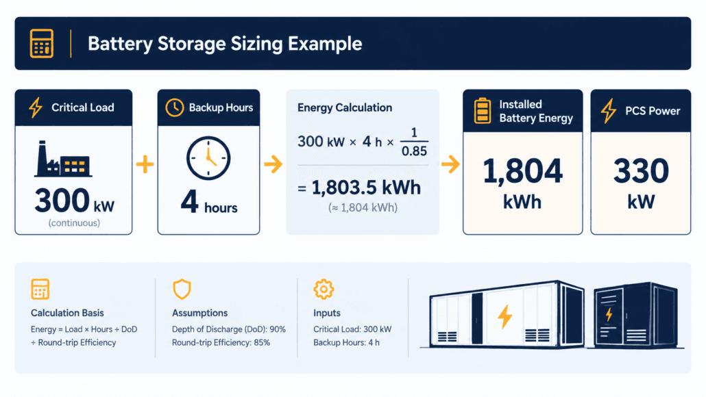
This worked example uses an 800 kW peak load and a 300 kW critical load. Backup duration is four hours.
Assumptions: 85% depth of discharge, 90% round-trip efficiency, 15% reserve margin. Also: 10% power margin, 0.90 power factor.
Nominal E/P duration: 1,804 ÷ 330 = 5.5 hours. That’s longer than the 4-hour target. DoD, RTE, and reserve margin together explain the gap.
This C&I BESS sizing calculator worked example uses one input combination. Change the backup duration to 2 hours, and installed battery energy roughly halves.
Push reserve margin to 20 percent instead, and it grows a little further. Run a few combinations of your own before settling on a target range.
Common C&I BESS Sizing Calculator Mistakes
These mistakes show up again and again in early estimates. But each one is easy to avoid once you know to check for it, and most take only a few extra minutes to correct before you share a number with anyone.
Ignoring DoD and RTE. In practice, sizing straight off delivered energy leaves a battery that cannot actually deliver the promised backup.
Skipping the reserve margin. Batteries lose usable capacity over time. A 10 to 15 percent margin, therefore, buys headroom for later years, not just day one.
Confusing power and energy. In short, a 330 kW PCS and a 1,804 kWh battery answer two different questions. Size both instead of just one.
Ignoring the required C-rate. For instance, a high C-rate can raise thermal stress and cut usable capacity under load. It can also affect cycle life and fall outside warranty limits. Confirm your chosen battery and PCS support the required rate.
Skipping fire code and siting review. NFPA 855, local fire and building codes, the authority having jurisdiction, and UL 9540A test evidence can all affect separation distances and layout. A preliminary estimate still needs a compliant site review. See our NFPA 855 guide for more detail.
Using nameplate load instead of running load. Nameplate and measured running load serve different purposes. Size the C&I BESS sizing calculator energy inputs off measured running kW, but review starting and transient loads separately for PCS sizing.
Skipping a sensitivity check. Run the calculator twice: once with conservative assumptions, once with optimistic ones. The gap between the two shows how much margin your estimate really has.
When You Need More Than a C&I BESS Sizing Calculator
Peak shaving, tariff optimisation, solar shifting, and generator integration all need more than one critical-load input. So do data centres and microgrids.
Peak shaving needs interval load data and your target demand level. Our demand charge guide covers why that line item is often 30 to 70 percent of a commercial bill.
Treat this calculator’s output as a starting point instead. Overall, bring it to an engineer, not to a procurement order.
Solar-plus-storage sizing is another case this C&I BESS sizing calculator does not cover. A hybrid system needs production profiles, self-consumption targets, and export limits alongside backup requirements.
Multi-building campuses work differently too. Size each building’s critical load separately, then combine the installed-energy totals rather than averaging duration targets across buildings.
Frequently Asked Questions
Quick answers to the most common C&I BESS sizing calculator questions, covering inputs, assumptions, and accuracy.
What inputs does a C&I BESS sizing calculator need?
At minimum: peak site load, critical load, and backup duration. Depth of discharge, round-trip efficiency, reserve margin, power margin, and power factor refine the estimate further.
What depth of discharge and round-trip efficiency should I use for LFP?
Most C&I LFP systems run 85 to 95 percent usable depth of discharge. Round-trip efficiency is usually 90 to 95 percent at the system level. Still, confirm exact figures with your manufacturer’s datasheet.
How much reserve margin should I add?
10 to 15 percent is a common starting point. It covers degradation, temperature swings, and load uncertainty. Still, longer contracts or harsher climates justify a larger margin.
Is a C&I BESS sizing calculator accurate enough for procurement?
No. Treat it as a preliminary estimate instead. Final sizing needs interval-load analysis, electrical design, site conditions, grid requirements, and product-specific warranty terms.
What’s the difference between installed and usable battery capacity?
Specifically, installed capacity is the nominal or nameplate energy capacity selected for the system. It is sized above the delivered-load requirement to account for DoD, system efficiency, and reserve margin. Usable capacity, by contrast, is the portion available within the selected DoD window.
Can this calculator size a multi-building campus?
Not directly in one pass. Run it once per building using each building’s own critical load and backup duration, then combine the installed-energy results before selecting a shared BESS.
How often should I re-run the calculator during a project?
Re-run it whenever a key input changes, such as an updated critical-load list, a revised backup target, or new DoD and RTE figures from a vendor quote. Treat early results as a starting range, not a fixed number.
Does this calculator account for battery degradation over time?
The calculator does not explicitly model year-by-year degradation. Its reserve margin is a user-selected allowance, not a validated end-of-life guarantee. Actual fade depends on chemistry, duty cycle, temperature, and your warranty terms.
Further Reading
More Sunlith guides pair well with this C&I BESS sizing calculator, covering fire code compliance, demand charges, and cost planning for C&I storage projects generally.
Disclaimer: This calculator and article provide preliminary estimates only. Final BESS sizing requires interval-load analysis, electrical engineering design, site assessment, applicable grid and fire codes, and manufacturer-specific validation.
You’ll find battery energy storage systems, or BESS, in settings ranging from portable power and rooftop solar homes to factories, construction sites, and grid-scale renewable projects. These systems all store and deliver electricity, but the types of BESS available differ substantially in size, packaging, controls, safety design, and grid connection.
First, matching the right type of BESS to your project starts with knowing what each one is built for.
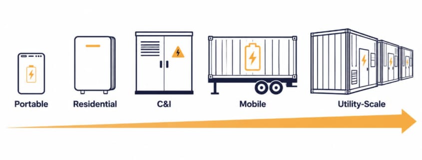
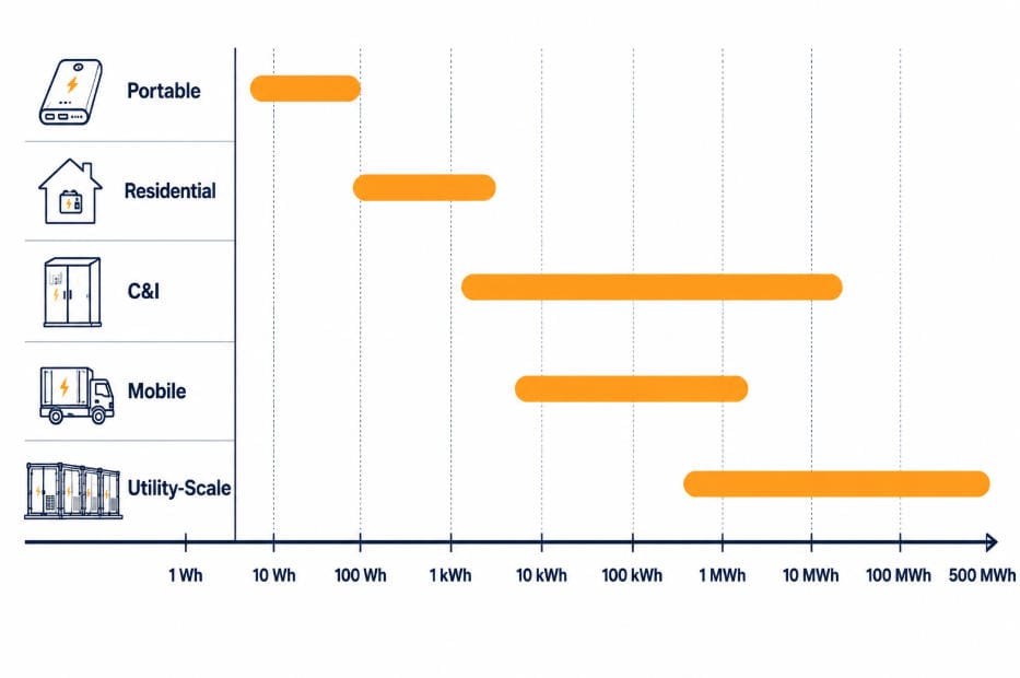
Quick Answer The five common types of BESS by application are portable, residential, C&I, mobile, and utility-scale. They range from compact systems storing watt-hours or a few kilowatt-hours to grid-connected projects storing hundreds of megawatt-hours.
BESS can also be classified by battery chemistry, system configuration, duration, or grid position. This guide focuses specifically on types of BESS by application — where the system is used and what it is designed to do.
Why There Are Different Types of BESS
Most rechargeable BESS combine batteries with monitoring and protection, power electronics, and thermal-control or enclosure features. But the exact architecture varies by size and application.
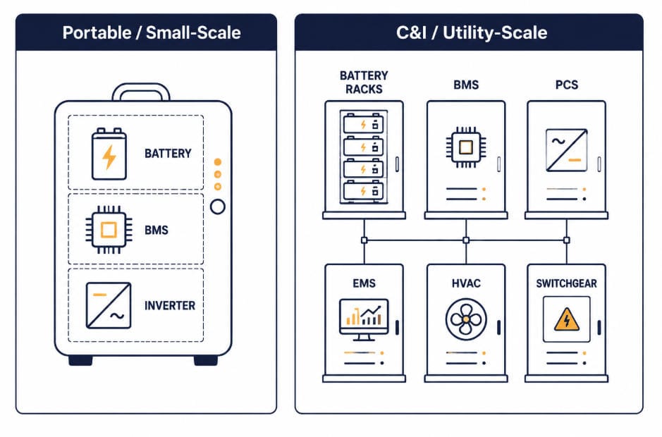
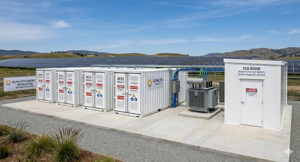
A portable power station often integrates these functions into one product. C&I and utility-scale projects, on the other hand, typically use dedicated subsystems instead: battery racks, a battery management system (BMS), a power conversion system (PCS), HVAC, fire protection, transformers, switchgear, and site controls.
An energy management system (EMS) is a separate, functional layer, not something that simply switches on above a size threshold. It coordinates charging and discharging according to site objectives, such as solar self-consumption, tariff optimization, backup reserve, generator reduction, or grid-service dispatch.
Large C&I and utility-scale projects generally require a dedicated EMS or site controller. Residential and portable products, meanwhile, often provide simpler embedded control functions instead. The underlying logic is similar; it’s just running at a smaller scale.
A few factors drive which type of BESS fits a given project:
How much power and energy the application needs, and for how long
What the system is trying to achieve — backup power, solar self-consumption, peak shaving, demand-charge reduction, generator reduction, energy arbitrage, or grid services
Whether the system stays in one place or moves
How it connects to the grid, and at what voltage level
What safety and compliance standards apply at that scale
Because of these differences, BESS spans a huge range. It ranges from a compact power station to a utility-scale installation that can occupy a large, purpose-designed site. For the full picture on how each type is built, see our complete guide to battery energy storage systems.
The 5 Types of BESS by Application
1. Portable BESS
Portable battery energy storage systems are compact, self-contained units built for power on the go. They typically range from a few hundred watt-hours to a few kilowatt-hours. Because they are small and easy to carry, they suit camping, remote work, field operations, and emergency response where power is needed without a permanent installation.
Most current portable power stations use lithium-ion cells, often lithium iron phosphate (LFP), because they offer a practical balance of energy density, cycle life, and safety characteristics. They typically combine the battery, inverter/charger, protection functions, and user controls in one enclosure rather than using a separate, dedicated PCS.
Portable units commonly include battery monitoring, protection, and temperature sensing. Unlike larger stationary systems, they generally do not require dedicated HVAC equipment or liquid-cooling loops.
They usually rely on embedded controls rather than a separate site-level EMS. Depending on the product, these controls may manage charging sources, output limits, backup behavior, or simple scheduling. The exact control and thermal design varies by product and power rating.
Home energy storage systems pair with rooftop solar to store excess daytime generation for evening use. Most residential systems run roughly 5-20 kWh. Larger systems, though, serve high-load homes, EV charging, electrified heating and cooling, or longer backup requirements.
In practice, the right size for a given household depends on its load profile, solar output, desired backup circuits, and target backup duration.
Installers commonly mount residential BESS units on a wall or floor. They connect through a hybrid inverter or a separate battery inverter, depending on the solar and electrical design, and include battery monitoring, protection, and thermal-control features built for long-term stationary operation.
Many also use energy-management logic for solar self-consumption, tariff optimization, backup reserve settings, or EV charging coordination. That’s a simpler, embedded version of the dispatch control found in larger C&I and utility-scale systems.
C&I battery energy storage systems serve businesses, factories, and campuses that want to cut demand charges, add backup resilience, or pair storage with on-site renewables. These systems generally range from tens of kilowatt-hours to several megawatt-hours.
Engineers often specify these systems by both power and duration — for example, 500 kW / 1 MWh or 2 MW / 4 MWh. That’s because a site’s peak load, tariff structure, backup requirement, and renewable-generation profile all shape the right configuration.
At this scale, however, design gets more involved. C&I systems typically need dedicated enclosures, active thermal management, and integration with a facility’s existing electrical infrastructure.
Depending on the site and jurisdiction, the design may include fire detection and suppression, emergency shutdown, HVAC or ventilation, electrical isolation and protection, access control, and remote monitoring.
We cover this application in depth across our C&I BESS series, starting with key components in C&I BESS — one of the most widely deployed types of BESS today.
4. Mobile BESS
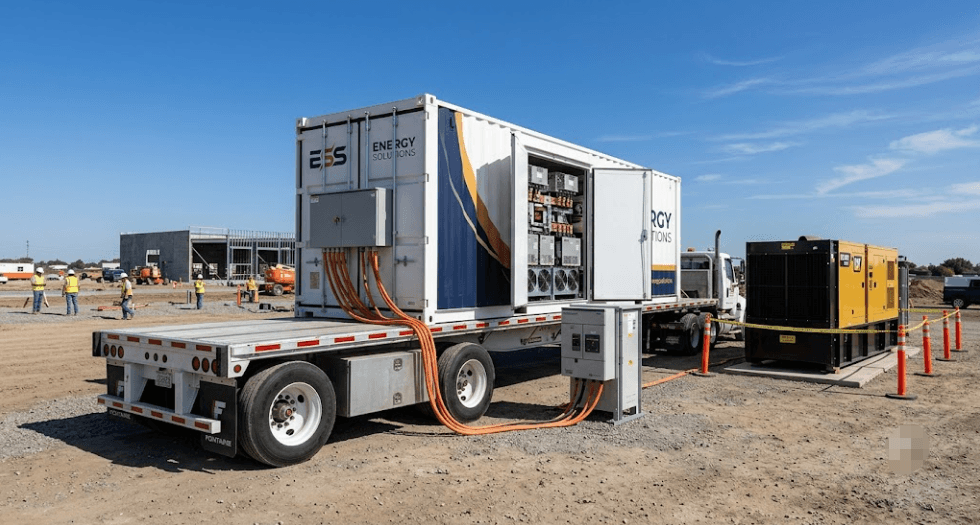
Mobile battery energy storage systems are trailer-mounted or containerized units that travel to wherever power is needed. That could mean a construction site, an event venue, a disaster response zone, or temporary grid support during planned outages.
Mobile BESS is often deployed alongside temporary grid connections, renewable generation, or diesel generators. In hybrid power setups, the battery can reduce generator runtime and improve generator loading efficiency.
It can also cover short-duration peak power. This is often the real economic case for choosing a mobile unit over a standard fixed C&I system.
Because they need to move, mobile units prioritize a rugged, self-contained design. They pack the battery, BMS, PCS, and often a built-in cooling system into a single towable or shippable unit. That trades some of the customization of a fixed installation for flexibility.
Learn more in our guide to mobile BESS, a uniquely flexible type of BESS built for temporary deployments.
5. Utility-Scale BESS
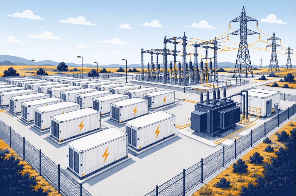
Utility-scale battery energy storage systems are the largest deployment type, ranging from several megawatt-hours to hundreds of megawatt-hours. They commonly use containerized or modular outdoor enclosures, combined with separate PCS, transformer, switchgear, protection, and control equipment.
The final layout depends on project capacity, duration, climate, fire-safety design, grid interconnection, and site constraints. So while containerized designs are common, they aren’t universal.
As a result, utilities, developers, and independent power producers deploy utility-scale BESS for frequency regulation, renewable-energy shifting and firming, capacity support, peak management, energy arbitrage, and other grid services.
Because of their size, these projects typically require detailed interconnection studies, protection coordination, dedicated switchgear, and coordination with the relevant grid operator. See the U.S. Department of Energy’s overview of grid-scale energy storage for more on how these systems support the wider grid. Utility-scale projects may connect at either distribution or transmission voltage, depending on the project’s rating.
Read our complete guide to utility-scale BESS, the largest of the five types of BESS by application, for the full picture.
Construction sites, events, disaster response, temporary grid support
Utility-Scale BESS
Several MWh to hundreds of MWh
Fixed, commonly containerized/modular
Frequency regulation, capacity firming, grid-scale renewable integration
Energy capacity indicates how much electricity a system can store. Power rating, expressed in kW or MW, determines how quickly it can charge or discharge.
How to Choose the Right Type of BESS
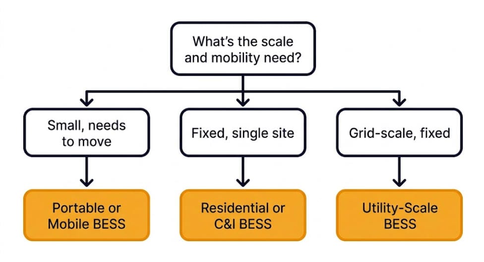
Picking the right type of BESS comes down to matching the system to the application:
Power and energy requirement — determine the kW/MW rating, the usable kWh/MWh capacity, and the required discharge duration. Their relationship matters: a 1 MW / 2 MWh system, for example, is built for about two hours of discharge at rated power, before accounting for operating limits and degradation.
Operating objective — solar self-consumption, peak shaving, backup power, generator reduction, arbitrage, or grid services each call for different controls and designs.
Mobility and site constraints — decide whether the system needs to be fixed, trailer-mounted, transportable, indoor, outdoor, containerized, or modular.
Grid connection and operating mode — systems may run off-grid, behind the meter, in a microgrid, or front of meter. Larger projects may interconnect at distribution or transmission level, depending on their power rating and local grid requirements.
Safety, permitting, and compliance — requirements vary by jurisdiction, installation location, fire strategy, electrical design, and project scale.
Budget and delivery timeline — factor in civil works, interconnection, switchgear, installation, commissioning, and ongoing operations and maintenance, not just equipment cost.
For most first-time buyers, matching the application to one of the five categories above is the fastest way to narrow down the right BESS type. Once that’s settled, these six factors help define the exact specification.
Conclusion
The right type of BESS depends first on the application. That means how much power and energy are needed, how long the system must operate, whether it needs to move, and how it will connect to the site or grid.
In general, portable and residential systems prioritize simplicity and compact design. C&I and mobile systems, meanwhile, balance resilience, flexibility, and site economics. Utility-scale projects, by contrast, are engineered for grid integration and large-scale dispatch.
Once you’ve identified the right application category, the next step is to define the required power rating, usable capacity, duration, site conditions, safety requirements, and control strategy. For a broader technical overview, see our complete guide to battery energy storage systems.
Frequently Asked Questions
What are the main types of BESS?
The main types of BESS by application are portable, residential, commercial and industrial (C&I), mobile, and utility-scale. Each one fits a different setting, from a few hundred watt-hours to hundreds of megawatt-hours.
What is the difference between a BESS and a battery?
In short, a battery is the electrochemical storage component. A BESS, however, is the complete system built around batteries, including battery monitoring and protection, power conversion, controls, thermal management, enclosure equipment, and — in larger projects — site-level safety and grid-interconnection equipment.
How are BESS systems classified besides application?
BESS can also be classified by battery chemistry, such as LFP or NMC. Other common classifications include system configuration (AC-coupled or DC-coupled), duration, mobility, and whether it operates behind the meter or front of meter. This guide classifies BESS by its end-use application.
What Size Should This Type of BESS Be for My Home?
Most residential systems run roughly 5-20 kWh. Larger systems, though, serve high-load homes, EV charging, or longer backup requirements — the right size depends on your household’s load profile, solar output, and desired backup circuits.
What’s the difference between C&I and utility-scale BESS?
C&I BESS typically ranges from tens of kilowatt-hours to several megawatt-hours, and serves a single business or facility. Utility-scale BESS is much larger, from several megawatt-hours to hundreds of megawatt-hours, and serves the broader grid instead of one site.
Which Types of BESS Can Be Moved Once Installed?
Fixed installations like residential, C&I, and utility-scale BESS generally don’t move once installed. Mobile BESS units are the exception — manufacturers build them specifically to be trailer-mounted or containerized for transport between sites.
Do all types of BESS use the same battery chemistry?
Most modern BESS across all five categories use lithium-ion batteries. Many new stationary systems use LFP chemistry because of its cycle-life and thermal-stability characteristics.
Chemistry can still affect system design, safety strategy, footprint, performance, and cost. However, this guide classifies BESS primarily by application, scale, packaging, and operating requirements.
NFPA 855, published by the National Fire Protection Association, is the U.S. standard for safe battery energy storage installation. If you’re developing, permitting, or financing a BESS project, compliance is not optional. In fact, your local fire marshal, your insurer, and your interconnecting utility will all check it first. This guide covers what the standard requires. It also covers what changed in the 2026 edition, and how the rules differ for C&I and utility-scale projects.
Quick Answer: What This Standard Covers
In short, this fire-safety standard sets the installation rules for battery storage in the United States. It covers spacing, ventilation, detection, suppression, and hazard analysis. That applies to everything from small residential batteries to utility-scale plants. Local fire codes enforce it. In addition, most insurers and interconnecting utilities require proof of compliance before they approve a project.
At a Glance
What it is: a National Fire Protection Association standard for stationary battery energy storage systems, first published in 2020, now in its 2026 (third) edition.
Who enforces it: local Authorities Having Jurisdiction (AHJs), typically through NFPA 1 (Fire Code) Chapter 52 or the International Fire Code Section 1207.
Who it applies to: residential, commercial, industrial, and utility-scale BESS. Specifically, the scope is set by battery chemistry and stored energy, not by project type alone.
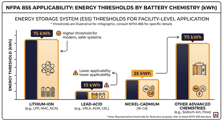
What triggers it: aggregate stored energy above chemistry-specific thresholds. For example, that’s 20 kWh for lithium-ion.
What’s new in 2026: a default requirement for Hazard Mitigation Analysis, large-scale fire testing, and stricter explosion control provisions.
What Does NFPA 855 Cover?
The standard addresses the full lifecycle of a battery energy storage system. That covers design, installation, commissioning, operation, maintenance, and decommissioning. In practice, most project teams also focus on five specific areas:
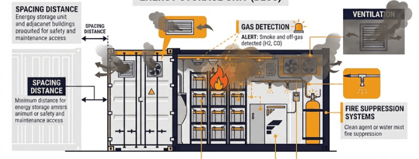
Separation and spacing — distances between battery units, and between the ESS and exposures like buildings, property lines, and other hazards
Fire detection and suppression — smoke and gas detection, plus sprinkler or other suppression systems sized to the installation
Ventilation — exhaust systems that keep flammable gas concentrations below dangerous thresholds
Explosion control — deflagration venting or prevention systems for enclosed spaces
Hazard Mitigation Analysis (HMA) — a documented assessment of thermal runaway, fire propagation, and toxic gas risks for the specific installation
Why Thermal Runaway Is the Core Hazard
Every requirement in this guide exists to control one underlying hazard: thermal runaway. It starts when a single battery cell overheats past a critical point. The cell then generates heat faster than it can dissipate it.
This can trigger a self-sustaining chain reaction, where one failing cell heats its neighbors until they fail too. In the worst case, that cascade spreads across an entire rack or unit.
NFPA 855’s core requirements each target a different stage of this chain. Spacing and separation slow how fast a failure can spread to nearby units. Gas detection catches early off-gassing before it ignites. Ventilation clears flammable gases before they reach dangerous concentrations. Suppression systems, meanwhile, cool cells enough to interrupt the cascade.
The newest layer is Thermal Runaway Propagation Prevention (TRPP). Importantly, this active system goes a step further by detecting early precursors like off-gassing or abnormal temperatures. Consequently, it automatically triggers a targeted response to stop the failure before it ever reaches a neighboring cell.
The Hazard Mitigation Analysis ties all of this together — it’s the engineering process, led by a qualified PE, that sizes each control to your project’s specific chemistry and configuration, instead of applying generic rules.
NFPA 855 Scope and Applicability
The first step is confirming the standard applies to your system at all. Applicability depends on battery chemistry and total stored energy, not project size alone. That said, below-threshold systems may fall outside full requirements. Your AHJ makes the final call.
Battery Chemistry
Below Threshold
At or Above Threshold
Lithium-ion
< 20 kWh aggregate (may be exempt)
≥ 20 kWh triggers full NFPA 855 requirements
Valve-regulated lead-acid (VRLA)
< 70 kWh aggregate (may be exempt)
≥ 70 kWh triggers full NFPA 855 requirements
Other battery chemistries
Threshold set per chemistry table (2026 lists chemistries alphabetically)
Confirm with your AHJ before assuming exemption
These thresholds still decide whether NFPA 855 applies to your system at all — that part hasn’t changed. What has changed is what happens once it does apply.
Previously, earlier editions let a project exceed the prescriptive threshold and still avoid a full Hazard Mitigation Analysis. It just had to stay under a separate “Maximum Stored Energy” cap in Chapter 9. The 2026 edition removed that cap entirely. As a result, once your system clears the Chapter 1 threshold, an HMA is the default requirement, not a fallback for oversized systems.
For example, a small server-room battery backup might still stay under 20 kWh and fall outside the standard’s full requirements. Almost any commercial, industrial, or utility-scale BESS, however, clears that threshold immediately. It now needs a documented HMA from the design stage, with no quantity-based way around it.
This standard runs on a three-year revision cycle. The 2026 edition, however, brought some of the most significant changes since its 2020 debut. Here’s what stands out for project developers, grouped by area.
Hazard Mitigation Analysis and Professional Oversight
Hazard Mitigation Analysis is now the default. Earlier editions required an HMA only in specific circumstances. The 2026 edition makes it the default requirement for most installations, with limited exceptions for well-understood chemistries like lead-acid.
A registered design professional must direct the risk assessment. Annex G now specifically names who should lead the Hazard Mitigation Analysis: a registered design professional (a licensed PE) experienced in fire protection engineering and energy storage risk assessment. The 2023 edition only referred to “parties,” with no qualification requirement attached.
New and Expanded Safety Systems
Thermal Runaway Propagation Prevention (TRPP) systems are now required. Section 9.7.6.6 introduces TRPP as a new, active fire-safety layer. Unlike passive features such as spacing or barriers, a TRPP system relies on active monitoring. Specifically, it detects early precursors like off-gas or abnormal temperatures. As a result, the system automatically triggers a targeted suppression or cooling response to stop the failure from spreading.
Large-scale fire testing (LSFT) plays a bigger role. Previous editions leaned on UL 9540A cell, module, and unit-level testing. The 2026 edition adds large-scale fire testing. In this test, a full unit burns under real-world conditions with suppression disabled. This validates worst-case performance.
Explosion-control guidance gets more specific. Annex G.8, which covers NFPA 69 evaluations for lithium-ion ESS, was revised with new engineering design and risk-mitigation considerations. Design teams now have clearer guidance for evaluating the consequences of an explosion event, not just whether one is possible.
Detection, Chemistry, and Emergency Planning
Detection methods expand for lithium-ion storage. Section 14.3.2.1.2 now allows smoke detection, thermal imaging, or radiant-energy detection installed per NFPA 72, replacing the older, narrower detection language. A related new section, 14.1.3, also lets batteries staged or stored temporarily at 50% state of charge or below skip full Chapter 14 compliance, under defined conditions.
Chemistry and application coverage expands. Additionally, the 2026 edition lists more battery chemistries. Furthermore, it drops the old subdivision between battery technologies and capacitor-based systems. It also adds two new chapters: Chapter 16 for flow batteries and Chapter 17 for energy storage systems on barges, plus expanded coverage of EV charging systems that include integrated energy storage.
Emergency planning becomes formal. The 2026 edition adds specific minimum requirements for an Emergency Response Plan and a training program. The plan must address mitigation, preparedness, response, and recovery, with an annual review and a yearly refresher training session that the AHJ is notified of.
Model fire codes take time to catch up. The 2024 International Fire Code, for example, still references NFPA 855-2023, not the 2026 edition. Many jurisdictions currently enforce that earlier version by default, even though NFPA has already published the newer standard. Because adoption timing varies by state and city, always confirm with your AHJ which edition actually governs your permit today, rather than assuming the newest edition automatically applies.
NFPA 855 Emergency Response and Backup Power Requirements
The 2026 edition adds two requirements that project teams commonly miss because they sit outside the usual spacing-and-suppression conversation.
Emergency Response Plan (ERP)
Every covered installation now needs a documented Emergency Response Plan. The plan must address four phases: mitigation, preparedness, response, and recovery. Facility operators must also run a training program for personnel, review the emergency operations plan annually, and hold a refresher training session every year. The AHJ must be notified when that training happens.
Emergency Power Supply Systems (EPSS/SEPSS)
New Section 4.10 requires that critical safety systems have reliable backup power. This applies to Emergency Power Supply Systems (EPSS) or Stored Emergency Power Supply Systems (SEPSS), built to NFPA 110 or NFPA 111. In practice, this means detection, suppression, and ventilation controls can’t silently fail during a grid outage. Per Section 4.10.22, the EPSS or SEPSS design must be available to the Fire Protection Engineer of record and the AHJ for review and approval, so this needs to enter the design package early, not as an afterthought during commissioning.
The core framework applies the same way across project types. Practical requirements, however, shift with scale.
Larger installations trigger stricter spacing and suppression requirements. Our C&I vs utility-scale BESS comparison covers the full picture. Utility-scale plants pack far more energy into open sites, so spacing tables scale up accordingly. C&I systems, meanwhile, sit next to occupied buildings and face tighter fire-marshal review instead.
C&I systems usually sit close to occupied structures. As a result, local fire marshal review and building setback rules carry extra weight alongside these requirements.
Utility-scale systems sit on purpose-built sites. Because of this, compliance centers more on large-scale fire testing data, explosion control, and emergency response planning coordinated with the local fire department.
Both project types need UL 9540A test data. Otherwise, they can’t satisfy the engineering basis for spacing and suppression design.
How NFPA 855 Relates to Other Standards
This standard doesn’t work alone. It references and depends on several other standards. Confusing them is a common, costly mistake.
Fire and Thermal Testing Standards
UL 9540 — the product-level safety certification for a complete energy storage system. Compliance also requires UL 9540-listed equipment.
UL 9540A — the test method that measures thermal runaway fire propagation. Its results set the engineering basis for spacing and suppression decisions. The 6th edition, published alongside the 2026 NFPA 855 cycle, expands the certification framework to address spacing and fire propagation directly, rather than leaving those as separate design considerations.
CSA/ANSI C800:25 — a newly published consensus standard for large-scale fire testing and ESS reliability. NFPA 855’s 2026 edition requires large-scale fire testing, but had no consensus test method to reference when it was finalized. CSA/ANSI C800:25 fills that gap, and NFPA has an open Tentative Interim Amendment (TIA Log No. 1852) proposing to formally reference it in Section 9.7. Worth tracking if you’re specifying test protocols today, since the reference may become official shortly after this guide’s publication.
Related Electrical, Grid, and Emerging Standards
IEEE 1547 — governs grid interconnection behavior for distributed energy resources. It sits outside this standard’s fire-safety scope, but it often appears in the same project approval package.
NEC Article 706 — the National Electrical Code section covering electrical installation requirements for energy storage systems above 1 kWh.
NFPA 800 (forthcoming) — a new Battery Safety Code currently under development, with public input accepted through January 2026. Once adopted, NFPA 800 is intended to address battery hazards across the full lifecycle, not just installation, and to complement NFPA 855. Over time, it may shift or replace some of the storage-specific provisions NFPA 855 currently covers. Worth watching if you’re planning a multi-year project timeline.
Use this sequence to build compliance into a project. Otherwise, you risk discovering requirements late, during permitting:
Confirm applicability — check your chemistry and stored energy against the current threshold table.
Then, select UL 9540-listed equipment with UL 9540A test data covering your configuration.
Complete a Hazard Mitigation Analysis, led by a registered design professional (PE) with fire-protection and energy-storage risk-assessment experience. The 2026 edition makes the HMA itself the default requirement, and Annex G now specifically calls for that qualification.
Also, design spacing, ventilation, detection, and suppression to the applicable chapter for your chemistry and installation type.
Add explosion control per NFPA 69, or document a performance-based alternative.
Draft an Emergency Response Plan covering mitigation, preparedness, response, and recovery, with an annual review and yearly refresher training built into your operating plan.
Confirm backup power for critical safety systems (EPSS/SEPSS per NFPA 110/111) and route the design through your Fire Protection Engineer and the AHJ before finalizing.
Finally, engage your AHJ early. Local adoption varies by state and jurisdiction. So, confirm which edition applies before finalizing your design.
Key Takeaways: NFPA 855
In short, this standard sets the fire-safety baseline for every battery energy storage system in the U.S., from a home battery to a utility-scale plant. The 2026 edition raises the bar with mandatory hazard analysis and large-scale fire testing. Compliance depends on chemistry, stored energy, and project scale. Therefore, the earlier you plan for it, the fewer surprises you’ll hit during permitting.
Frequently Asked Questions
Is NFPA 855 a Law or a Standard?
NFPA 855 is a consensus standard, not a law by itself. However, it carries legal weight once a jurisdiction adopts it, typically through NFPA 1 or the International Fire Code. Because adoption varies by state and city, always confirm which edition your local AHJ enforces.
Does It Apply to All Battery Chemistries?
Yes. The standard is technology-neutral and covers lithium-ion, lead-acid, flow batteries, nickel-based systems, and others. Each chemistry gets its own energy threshold. Consequently, the same project might qualify for an exemption under one chemistry and not another.
What’s the Difference Between UL 9540A and NFPA 855?
UL 9540A is a test method. It measures how far a fire propagates inside a battery system. NFPA 855, meanwhile, is the installation standard that uses those test results to set spacing, suppression, and separation requirements. Ultimately, you need UL 9540A data to satisfy it, not the other way around.
Does Compliance Differ for C&I vs Utility-Scale BESS?
The core framework stays the same, but practical requirements scale with the project. Utility-scale plants face larger spacing tables and heavier reliance on large-scale fire test data. C&I systems, meanwhile, face tighter scrutiny from local fire marshals, because they sit closer to occupied buildings.
When Does the 2026 Edition Take Effect?
NFPA publishes new editions on a regular three-year cycle, and 2026 follows that schedule. Model fire codes typically adopt a given edition about a year later. Because of this, check with your local AHJ to confirm which edition governs your permit application today.
Is Large-Scale Fire Testing Fully Standardized Yet?
Not completely. NFPA 855:2026 requires large-scale fire testing, but no consensus test method existed when the edition was finalized. CSA/ANSI C800:25, published shortly after, is expected to fill that role. NFPA has an open Tentative Interim Amendment proposing to formally reference it in Section 9.7. Until that TIA resolves, confirm your test protocol directly with your AHJ and testing lab.
C&I vs utility-scale is the first question every solar or battery storage project must answer. The two terms sound like simple size labels. In reality, they describe two very different businesses. Not only do they serve different customers, but they also connect to the grid differently and rely on entirely unique financing and equipment. This guide walks through the full C&I vs utility-scale comparison, section by section, so you know exactly which one applies to your project.
⚡ Quick Answer: C&I vs Utility-Scale In short, C&I vs utility-scale comes down to one factor: what sits behind the grid connection. A C&I system serves a single business site and lowers that site’s own electricity bill. A utility-scale system, on the other hand, connects straight to the grid and sells power to the wider market. Everything else — size, financing, interconnection, and equipment — follows from that one distinction.
C&I vs Utility-Scale: Key Differences at a Glance
Before the full breakdown, here’s the short version of the comparison:
Size: C&I typically runs 100 kW to 10 MW. Utility-scale typically runs 20 MW to 500+ MW.
Connection: C&I sits behind the meter. Utility-scale sits in front of it.
Revenue: C&I saves money on one facility’s bill. Utility-scale earns revenue from the wholesale market.
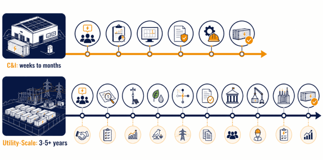
Timeline: C&I projects often finish in months. Utility-scale projects often take years.
Ownership: hosts or third-party lessors typically own C&I systems. Independent power producers typically own utility-scale plants.
What Does C&I Mean?
C&I stands for Commercial and Industrial. In the BESS world, it describes systems installed at a business’s own site. Picture a factory, a warehouse, a distribution center, or a hospital. These systems serve that facility’s own electricity needs. Specifically, C&I systems typically range from 100 kW to a few megawatts (MW). Large industrial campuses can reach 5–10 MW.
A C&I system sits behind the customer’s meter. Its main job is cutting that facility’s electricity bill, not selling power onto the grid. For that reason, businesses deploy C&I storage for several reasons:
Demand charge reduction — the battery discharges during peak demand and shaves the facility’s peak draw. Utilities bill demand separately from energy, often heavily. As a result, peak shaving delivers one of the fastest paybacks in the industry.
Time-of-use (TOU) arbitrage — the system charges when electricity is cheap and discharges when it’s expensive.
Backup power — stored energy keeps critical loads running through an outage.
Solar self-consumption — pairing storage with on-site solar lets the facility use more of its own generation instead of exporting it.
Demand response — the facility earns payments for cutting load when asked.
In addition, every one of these applications runs on the same core hardware — batteries, inverters, and enclosures — covered in our guide to the key components of a C&I BESS.
What Does Utility-Scale Mean?
Utility-scale storage means large power plants. Some call it grid-scale or front-of-the-meter storage. These plants typically run from tens of megawatts to several hundred megawatts. The largest projects reach the gigawatt range for total energy capacity. Unlike C&I systems, utility-scale plants don’t serve one building. Instead, they connect directly to the transmission grid or a high-voltage line, and they sell power and grid services into the wholesale market.
Developers build, own, and operate these projects as standalone power plants. Revenue comes from several sources:
Power purchase agreements (PPAs) with a utility or corporate offtaker
Wholesale energy market sales — buying low and selling high across the day
Ancillary services, such as frequency regulation, spinning reserve, and capacity payments
Resource adequacy and capacity markets, which pay the plant to stay available during system peaks
Most people reach for size first when they compare C&I vs utility-scale projects. But size is only a side effect, not the real distinction. The true dividing line is simpler: does an existing load sit behind the grid connection?
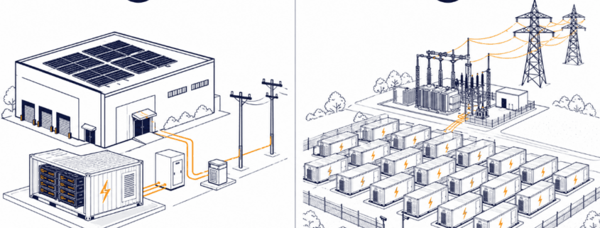
A C&I plant connects at a site with an existing load — a factory, a data center, a logistics hub — and the battery interacts with that load. A utility-scale plant, by contrast, connects at a site built only for the plant itself. No meaningful load sits behind it. The plant exists purely to generate or store energy for the grid.
This explains an unusual case. A data center with tens of megawatt-hours of storage still counts as C&I, because a load sits behind the meter. A small dedicated battery plant on a remote substation still counts as utility-scale, because no load does. In short, size alone never decides the category.
C&I vs Utility-Scale: Side-by-Side Comparison
The table below summarizes the core C&I vs utility-scale differences at a glance.
Attribute
C&I
Utility-Scale
Typical size
~100 kW – 10 MW
~20 MW – 500+ MW
Connection point
Behind the customer’s meter, low/medium voltage
Front-of-the-meter, transmission or sub-transmission voltage
Primary customer
The host facility (factory, warehouse, campus)
The grid / wholesale market / utility offtaker
Main value streams
Demand charge reduction, TOU arbitrage, backup power, self-consumption
Energy arbitrage, capacity payments, ancillary services, PPA revenue
Ownership model
Facility owner, third-party PPA/lease, or ESA
Independent power producer (IPP), utility, or institutional investor
Site control
Existing commercial/industrial property
Purpose-acquired land, often rural
Interconnection process
Utility’s commercial/small-generator process
RTO/ISO or utility large-generator interconnection queue
Typical BESS duration
1–4 hours
2–8+ hours, growing interest in long-duration storage
Design driver
Facility load profile and tariff structure
Market price signals and grid needs
Permitting complexity
Lower — usually local/municipal
Higher — environmental review, land use, transmission studies
Typical project timeline
Months
Multiple years, often 3–7 years including interconnection queue
Typical payback / horizon
3–7 years, driven by demand charges and tariff spreads
10–15+ years, underwritten by long-term PPA and market revenue
C&I vs Utility-Scale: Technical Differences
Size and connection point drive real engineering differences between C&I vs utility-scale systems. Here’s how they show up in practice, category by category.
Voltage and Interconnection Equipment
C&I systems usually interconnect at low voltage (400–480V) or medium voltage (4.16–34.5 kV). They tie directly into a building’s electrical service or a nearby feeder. Utility-scale systems, however, interconnect at transmission-class voltages, often 69 kV and above. That higher voltage requires dedicated substations, step-up transformers, and compliance with the utility’s or ISO’s large-generator interconnection agreement.
Control and Dispatch Strategy
A C&I energy management system (EMS) tunes itself around the host facility’s own load curve. Specifically, it tracks peak demand windows and the site’s utility tariff. A utility-scale EMS, in contrast, tunes around market price signals and grid-operator dispatch instructions. Increasingly, it also stacks multiple revenue streams at once — a practice the industry calls value stacking.
Duration, Cycling, and Modularity
C&I batteries commonly run 1–4 hour discharge durations, matched to typical demand-charge windows. Utility-scale batteries, meanwhile, increasingly target longer durations — 4, 8, or more hours — to cover evening peaks as solar output fades. As a result, they also cycle more predictably against known market patterns.
Physical layout differs too. C&I deployments often use a few large enclosures sized to fit an existing footprint, such as a rooftop or a parking area. Utility-scale projects, by comparison, deploy dozens to hundreds of containerized units across open land, in a standardized layout built for construction speed.
Inverter Control Mode
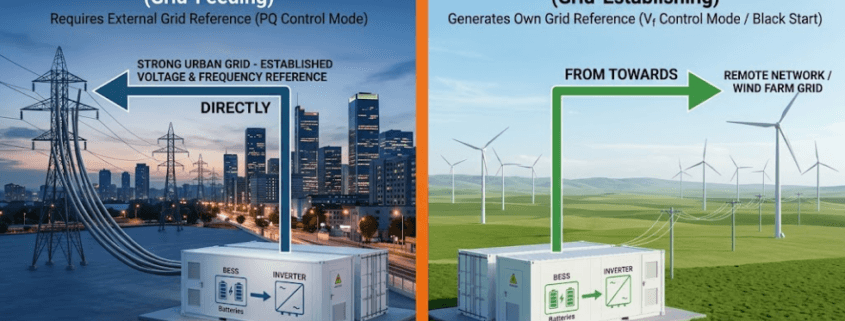
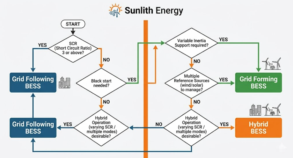
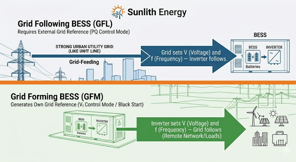
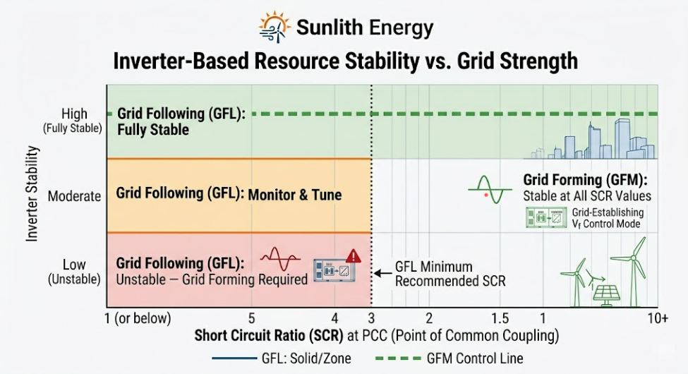
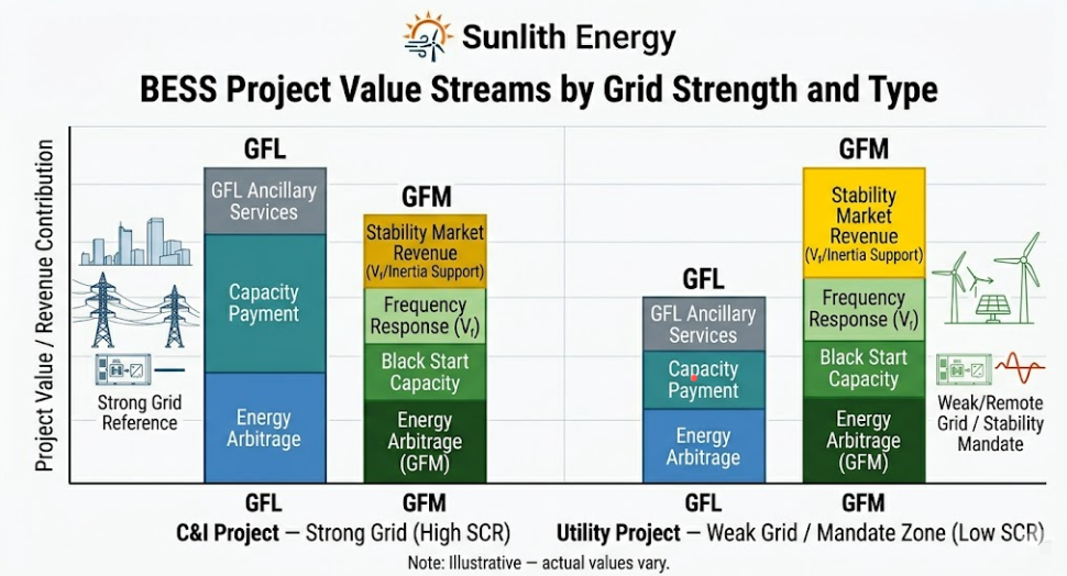
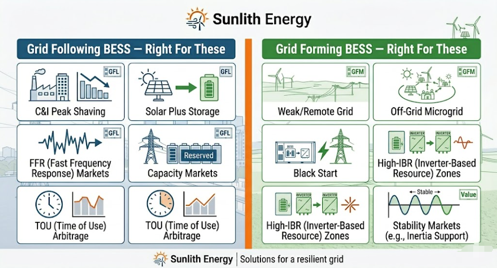
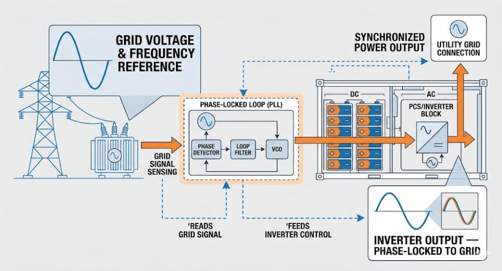
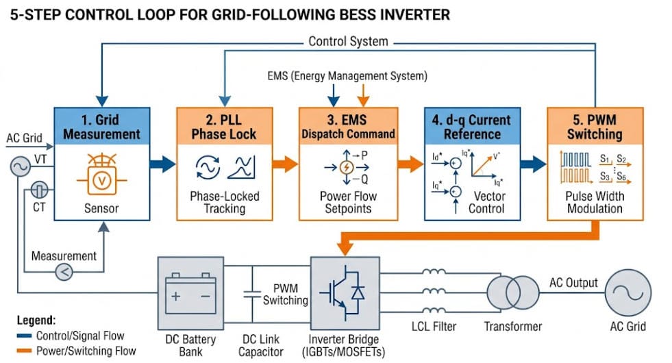
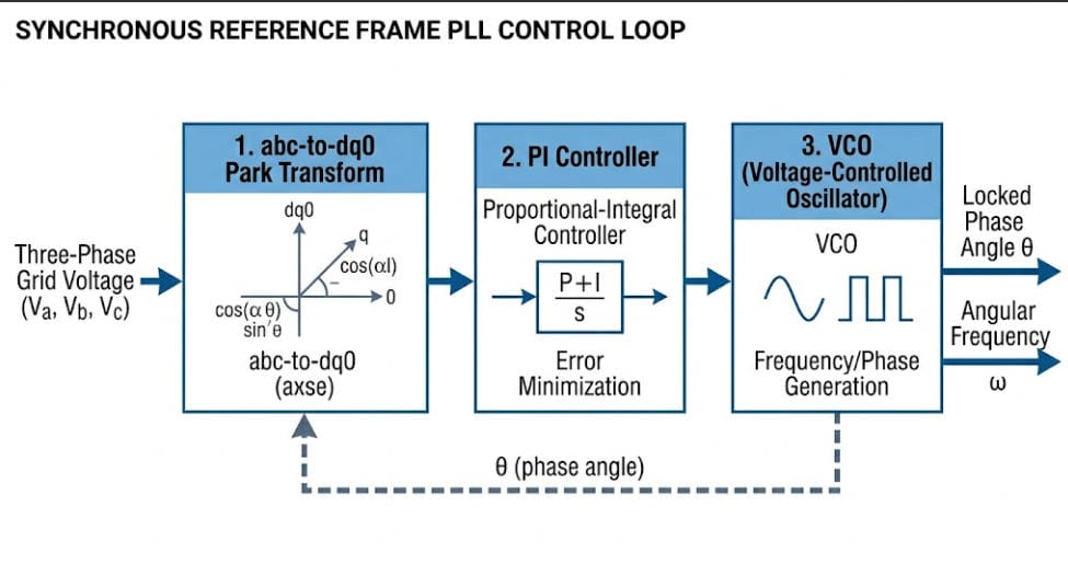
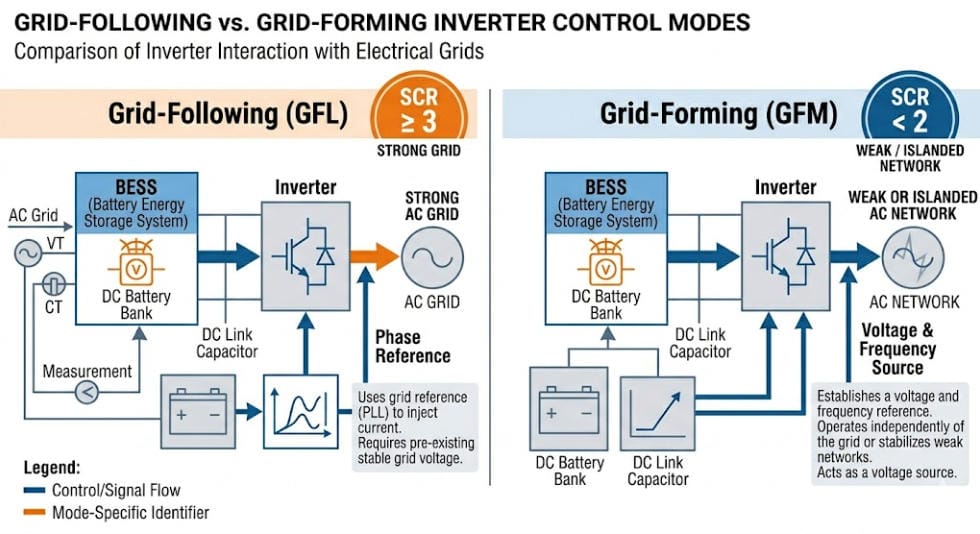
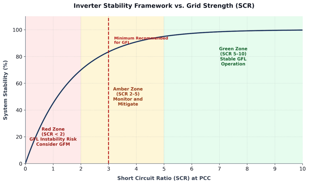
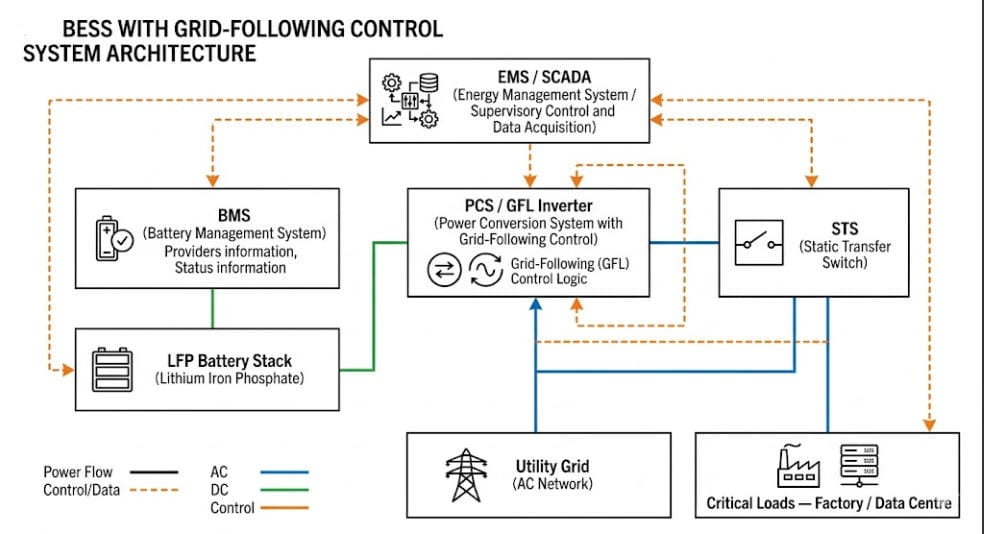
Roughly 80–85% of all BESS installed worldwide today use grid-following (GFL) inverters, which lock onto an existing grid signal. Utility-scale projects, however, increasingly specify grid-forming (GFM) inverters instead. These can lightweight-synthesize their own voltage and frequency reference, support black start, and provide synthetic inertia.
While those capabilities matter far more at grid scale than behind a single facility’s meter, there is a major exception emerging in the C&I space: advanced microgrids. High-reliability C&I applications—such as islanded critical infrastructure, data centers, or remote mining sites—are actively adopting grid-forming inverters. This allows the facility to safely intentional-island from the main grid during an outage and maintain seamless, resilient operations on its own terms.
Codes and Standards
Both categories follow UL 9540 for energy storage systems, UL 9540A for thermal runaway fire testing, and NFPA 855, the primary U.S. fire code for stationary energy storage. or a deep dive into the latest safety rules, spacing requirements, and hazard testing under this framework, read our comprehensive NFPA 855 guide.
Utility-scale sites, however, carry extra requirements tied to grid interconnection standards. Examples include IEEE 1547 for distributed resources and FERC/NERC reliability rules for transmission-connected assets. C&I systems, meanwhile, must satisfy local fire marshal and building code review, since they sit next to occupied buildings.
C&I vs Utility-Scale Interconnection Process
Interconnection turns the C&I vs utility-scale comparison into a real scheduling and risk problem, not just an engineering one.
C&I Interconnection
A C&I system typically goes through the utility’s existing commercial or small-generator interconnection process. Because the site already connects to the grid, the project doesn’t need new transmission infrastructure. As a result, timelines usually run from a few weeks to a few months.
Utility-Scale Interconnection
A utility-scale project must apply to the regional transmission organization (RTO) or independent system operator (ISO), or to the relevant utility, through a large-generator interconnection queue. FERC sets the federal rules for this process, which includes system impact studies and facilities studies. It often requires the developer to fund network upgrades the studies identify.
Interconnection queues in many U.S. regions now run 3–5+ years. Some run much longer. Because of this, interconnection timing is one of the biggest risk factors in utility-scale project development.
C&I vs Utility-Scale: Financing and Economics
C&I projects usually rely on financing built for a single host customer. A business might pay cash, sign a storage lease, or use a third-party-owned power purchase agreement, where a developer owns the system and the host simply pays for the savings it delivers. Payback typically lands in the 3–7 year range, depending on local demand-charge structure. For the full ROI math, see our guide to C&I BESS economics.
Utility-scale projects, by contrast, raise money as standalone infrastructure assets. Developers combine tax equity, debt from infrastructure lenders, and a long-term PPA that underwrites the debt. Because no single host’s bill defines success, the economics depend on wholesale market forecasts and interconnection terms. Investment horizons commonly run 10–15+ years. For the full framework on calculating storage ROI, see our guide to the economics of BESS.
Permitting complexity follows the same pattern. C&I projects mainly clear local and municipal review. Utility-scale projects, however, add environmental review, land-use approval, and formal interconnection studies on top.
C&I vs Utility-Scale: Which One Fits Your Project?
The right category isn’t really a choice. It follows from the problem you’re solving.
If the goal is to lower one facility’s bill, add resiliency, or manage demand charges, C&I is the answer — sized and controlled around that facility’s own load and tariff.
If the goal is to earn revenue by selling power or grid services into the wholesale market, utility-scale is the answer — sited and interconnected as a standalone power plant.
Some organizations pursue both. For example, a large industrial company might install a C&I system at its own plant while also investing in a utility-scale project as a corporate PPA offtaker. Either way, the two remain distinct engineering and financial exercises, even inside the same company.
Key Takeaways: C&I vs Utility-Scale The C&I vs utility-scale decision starts with one question: is there a load behind the meter? If yes, the project is C&I. If no, it’s utility-scale. Everything else — voltage, control strategy, financing, and interconnection — follows from that single fact.Sunlith Energy reviews incoming cell test data, matching tolerances, and pack assembly quality control for BESS projects from 50 kWh upward. Contact us before you finalize a cell or pack supplier.
C&I vs Utility-Scale FAQs
Is a community solar project C&I or utility-scale?
Community solar projects behave more like small utility-scale assets. They interconnect to the distribution grid and sell subscriptions, rather than serving one host’s load. That said, they’re usually smaller — 1–5 MW — than a traditional utility-scale plant.
Can a C&I battery ever sell power back to the grid?
Some C&I systems do join demand response or limited export programs. Even so, their main job stays the same: cut the host facility’s own costs. That’s what separates them from front-of-the-meter assets built mainly to sell power.
Does utility-scale mean the utility owns it?
Not necessarily. Independent power producers and investment funds own many utility-scale plants. They simply sell power to a utility or corporate buyer under a PPA. In other words, the term describes the scale and grid connection point, not the owner.
Why do C&I projects move faster than utility-scale projects?
C&I systems interconnect at lower voltage through a simpler utility process. They usually skip new transmission infrastructure entirely. As a result, they avoid the multi-year interconnection queues that utility-scale projects face at the transmission level.
Is project size or the meter connection the real dividing line?
The meter connection decides it. A large facility with tens of megawatt-hours of storage still counts as C&I, because a load sits behind the connection. A small dedicated battery plant on a remote substation still counts as utility-scale, because no load does.
The BESS PCS — Power Conversion System — converts DC battery power to AC for loads or the grid. However, what a PCS must do beyond that basic job changes completely depending on the application. Consequently, choosing the wrong PCS type is one of the most expensive mistakes a project team can make.
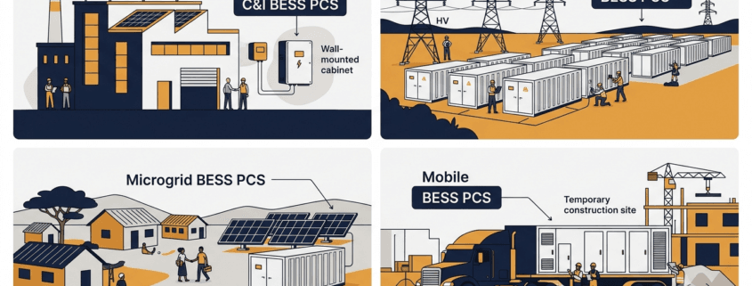
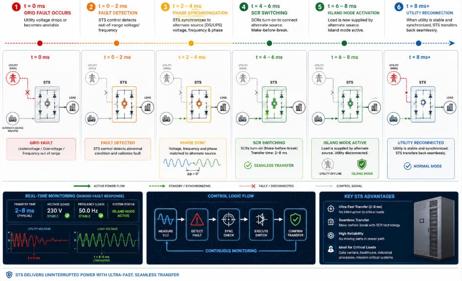
Consider four scenarios. A factory running peak shaving needs a PCS that switches to backup mode within 20 ms. By contrast, a 200 MW grid project needs sub-200 ms frequency response and reactive power control. An island microgrid, meanwhile, needs the PCS to synthesise the AC voltage reference — because no utility connection exists at all. Finally, a mobile BESS on a trailer needs ruggedness and fast site commissioning above all else.
Therefore, this guide covers each of the four application types in detail. Furthermore, it includes a master comparison table so you can see exactly which PCS functions are mandatory, optional, or not needed for each system type. By the end, you will have a clear framework for evaluating any BESS PCS proposal.
What Is a BESS PCS?
Inside every battery energy storage system, the Power Conversion System converts DC from the battery cells to AC for loads or the grid. During charging, it reverses direction and converts AC back to DC. Crucially, both functions share a single hardware platform — hence the term bidirectional.
As Sunlith’s PCS vs. Inverter guide explains, a PCS includes far more than just a bidirectional inverter. In addition, it handles reactive power control, protection functions, grid synchronisation, and communication with the BMS and EMS. According to NLR’s Power Electronics research, the PCS is one of the most critical components in grid-connected storage — because its control functions directly determine grid stability and service quality.
Moreover, the Bidirectional Inverter vs PCS comparison on this site highlights PCS-specific capabilities — including multi-port DC support, islanding, and black start. None of these are available in a stand-alone inverter. However, which of these capabilities you actually need depends entirely on your application type.
Four Application Types at a Glance
Before diving into each type, here is a quick overview showing how the four BESS application categories differ in their primary PCS priorities.
System Type
Typical Power
Grid Connection
Primary PCS Priority
C&I (Behind-the-Meter)
30 kW – 2 MW
Grid-connected, LV/MV
Peak shaving, backup power, solar integration
Utility Scale (Front-of-Meter)
2 MW – 500 MW+
Grid-connected, MV/HV
FFR, reactive power, grid code compliance
Microgrid / Off-Grid
10 kW – 50 MW
Islanded or weak grid
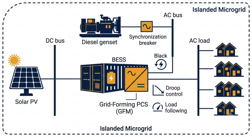
Grid-forming, black start, load following
Mobile BESS
50 kW – 5 MW
Temporary grid or off-grid
Portability, ruggedness, fast commissioning
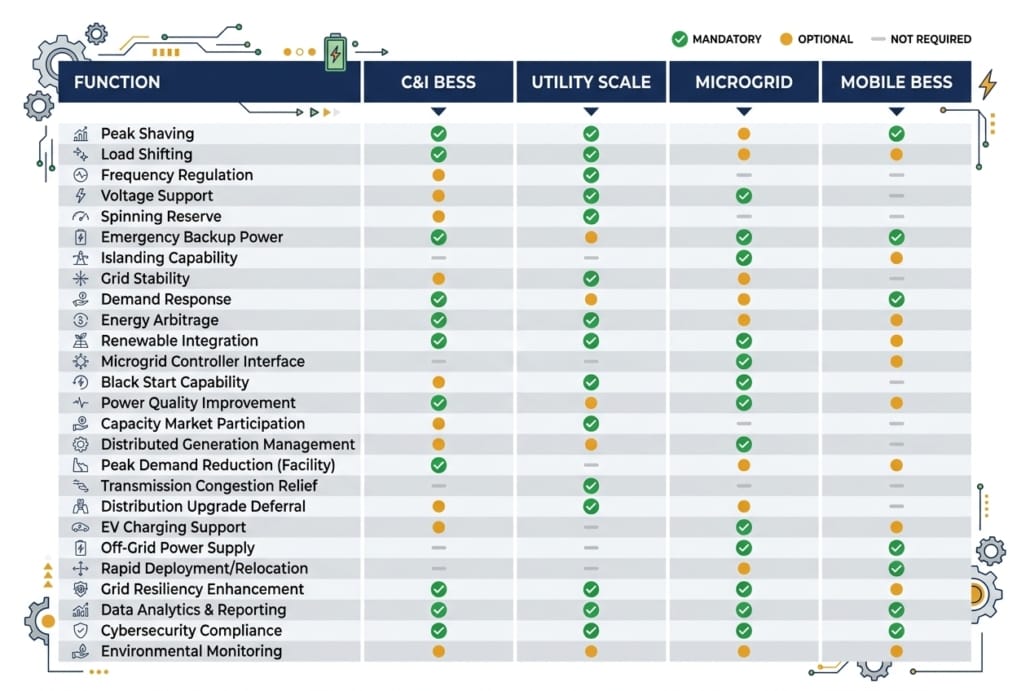
Master Comparison Table: BESS PCS Functions by Application Type
Use this table to compare PCS requirements across all four system types. Functions marked ✔ Mandatory must be specified and tested. Those marked ◉ Optional are recommended in certain site conditions. Those marked ✘ Not Required are not applicable to that system type.
PCS Function / Feature
C&I BESS
Utility Scale
Microgrid / Off-Grid
Mobile BESS
Bidirectional AC-DC Conversion
✔ Mandatory
✔ Mandatory
✔ Mandatory
✔ Mandatory
Peak Shaving / Load Shifting
✔ Mandatory
✘ Not Required
✘ Not Required
◉ Optional
Seamless Transfer / UPS Mode
✔ Mandatory
✘ Not Required
✔ Mandatory
✔ Mandatory
Solar PV Integration (AC/DC)
✔ Mandatory
◉ Optional
✔ Mandatory
◉ Optional
Fast Frequency Response (FFR)
✘ Not Required
✔ Mandatory
✘ Not Required
✘ Not Required
Primary Frequency Response (PFR)
✘ Not Required
✔ Mandatory
◉ Optional
✘ Not Required
Reactive Power (Q) Control
◉ Optional
✔ Mandatory
◉ Optional
✘ Not Required
LVRT / HVRT (Ride-Through)
◉ Optional
✔ Mandatory
✘ Not Required
◉ Optional
Grid-Following Mode (GFL)
✔ Mandatory
✔ Mandatory
◉ Optional
✔ Mandatory
Grid-Forming Mode (GFM)
✘ Not Required
◉ Recommended
✔ Critical
◉ Optional
Black Start Capability
✘ Not Required
◉ Optional
✔ Critical
◉ Optional
Droop Control
✘ Not Required
◉ Optional
✔ Critical
◉ Optional
Load Following
✘ Not Required
✘ Not Required
✔ Critical
◉ Optional
Genset Synchronisation
✘ Not Required
✘ Not Required
✔ Critical
✔ Mandatory
Time-of-Use (TOU) Scheduling
✔ Mandatory
✘ Not Required
✘ Not Required
◉ Optional
Multi-Port DC Input (PV + Battery)
◉ Optional
✘ Not Required
✔ Mandatory
◉ Optional
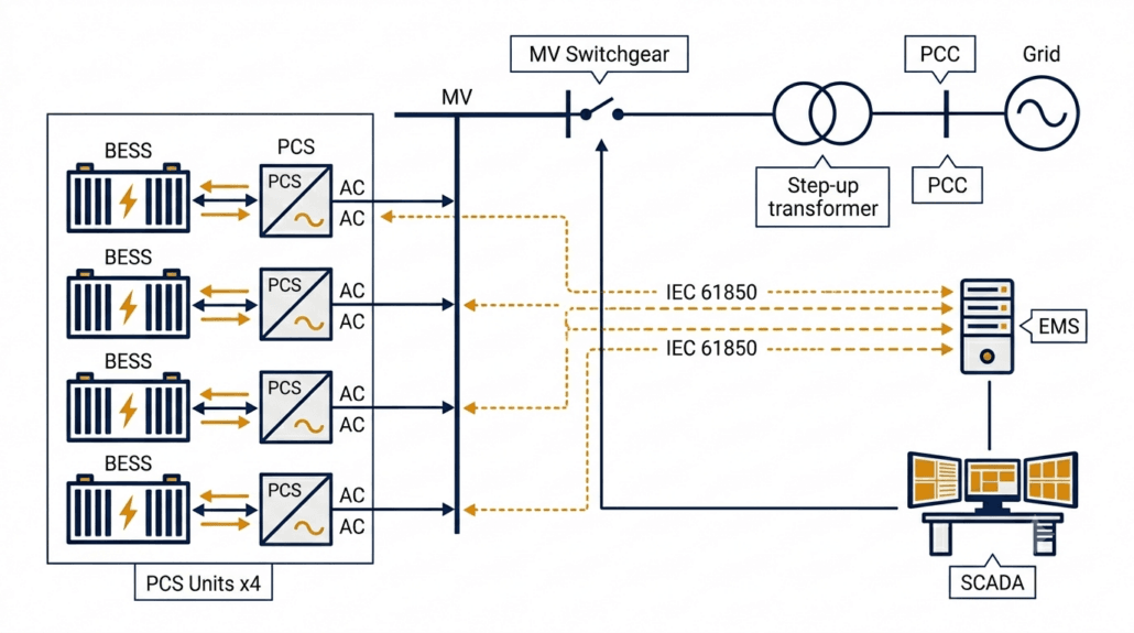
IEC 61850 / SCADA Integration
✘ Not Required
✔ Mandatory
◉ Optional
✘ Not Required
Modbus TCP / EMS Communication
✔ Mandatory
✔ Mandatory
✔ Mandatory
✔ Mandatory
Wide DC Input Voltage Range
✘ Not Required
✘ Not Required
✔ Mandatory
✔ Mandatory
Overload Capability (150–200%)
✘ Not Required
✘ Not Required
✔ Critical
✔ Mandatory
Compact / Trailer-Mount Design
✘ Not Required
✘ Not Required
✘ Not Required
✔ Critical
Rapid Commissioning (< 4 hrs)
✘ Not Required
✘ Not Required
✘ Not Required
✔ Critical
IP55+ Outdoor Enclosure
◉ Optional
✔ Mandatory
✔ Mandatory
✔ Critical
Noise Level < 65 dB(A)
✔ Mandatory
✘ Not Required
◉ Optional
◉ Optional
NERC CIP / Cybersecurity
✘ Not Required
✔ Mandatory
✘ Not Required
✘ Not Required
Legend: ✔ Mandatory = must be specified and verified at FAT | ◉ Optional = recommended for certain conditions | ✘ Not Required = not applicable
Which PCS functions are mandatory, optional, or not needed? This comparison covers all four BESS application types in one quick-reference chart.
C&I BESS PCS Functions and Features
A C&I — Commercial and Industrial — BESS sits behind the utility meter, serving loads inside a building or factory. Unlike utility systems, its PCS does not need to meet grid operator mandates. Instead, it must respond to site-level conditions to deliver financial returns. Specifically, the financial case comes from cutting demand charges, shifting energy to cheap tariff windows, and providing backup power during outages.
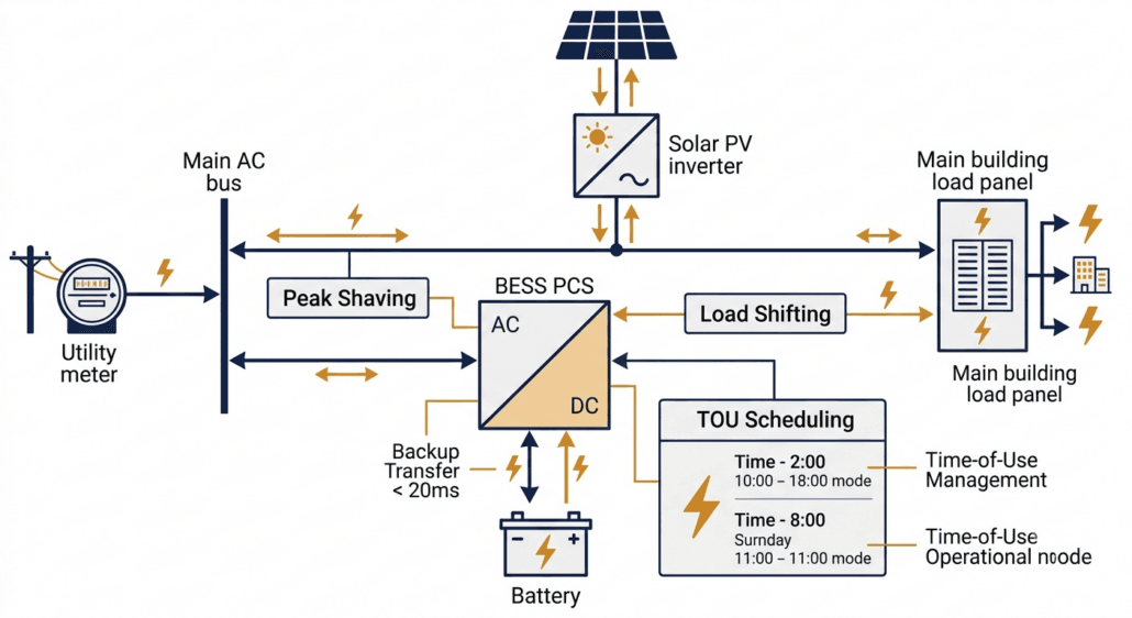
In a C&I system, the PCS manages power flow between the utility meter, solar array, and site loads — all simultaneously.
Peak Shaving and Time-of-Use Scheduling
Peak shaving is the most financially important C&I BESS PCS function. Demand charges can account for 30–50% of a commercial electricity bill. Therefore, the PCS charges the battery during low-demand periods and then discharges during peak demand to reduce the demand reading at the meter. Furthermore, time-of-use (TOU) scheduling shifts energy consumption into cheaper tariff windows, reducing energy cost on top of the demand saving.
Both functions require the PCS to support scheduled cycles via the EMS. Additionally, the PCS must respond to dynamic tariff signals from the utility in real time. As the IEA’s Grid-Scale Storage report notes, demand-side flexibility is one of the fastest-growing commercial storage applications globally. Consequently, TOU scheduling is now a baseline requirement in most C&I BESS tenders.
Seamless Transfer and Backup Power
When the grid fails, the C&I BESS PCS must switch to island mode fast enough to protect sensitive equipment. This transfer — called a seamless transfer or UPS mode — must complete within 20 ms for most commercial sites, and within 10 ms for data centres or precision manufacturing. Critically, seamless transfer is not a standard feature on all PCS products, so buyers must list the maximum allowed transfer time explicitly in their specification.
Furthermore, the PCS must be able to supply the full site load in island mode — not just a fraction of it. Therefore, both the transfer time and the island-mode power rating must be tested during factory acceptance testing (FAT). Accepting a vendor declaration without live testing is a common and expensive commissioning mistake.
Solar PV Integration
Most C&I BESS projects include rooftop or carport solar PV, so the PCS must integrate with the solar inverter. Two integration methods are available. AC coupling connects the solar inverter and PCS on the same AC bus — straightforward to retrofit, though energy passes through two conversion stages, which adds losses. DC coupling, by contrast, connects solar panels directly to the BESS DC bus via a DC-DC converter inside the PCS. This cuts conversion losses significantly. However, DC coupling requires the PCS to support multi-port DC input, so buyers must specify this feature explicitly at procurement stage.
C&I PCS Key Specifications
Power Range: 30 kW – 2 MW continuous output
Seamless Transfer: < 20 ms to island mode (< 10 ms for critical loads)
TOU Scheduling: Via EMS with dynamic tariff integration
Solar Integration: AC-coupled or DC-coupled PV input support
Grid Code: IEEE 1547 / UL 1741-SA for LV interconnection
Noise: < 65 dB(A) at 1 m for indoor installations
Communications: Modbus TCP to site EMS or BMS
Utility Scale BESS PCS Functions and Features
A utility-scale BESS connects to the medium or high-voltage grid in front of the meter. Consequently, its PCS must comply with grid operator requirements — legal obligations rather than performance suggestions. These requirements are more precise, more rigorously enforced, and technically more demanding than anything a C&I project faces. Therefore, a utility-scale PCS is a genuinely different machine from a C&I unit, even if the basic conversion function is the same.
At utility scale, multiple PCS units run in parallel, feeding through a step-up transformer to the grid, with full IEC 61850 SCADA integration.
Fast Frequency Response (FFR)
FFR is the most commercially valuable utility-scale PCS function. When grid frequency drops — for example, because a large generator trips — the PCS must detect the deviation and ramp power within milliseconds. Most grid operators set the response window at 200 ms. However, some markets require 150 ms, and AEMO in Australia now tenders for sub-100 ms response.
To achieve these targets, the PCS control loop must use a dedicated high-speed frequency measurement algorithm — standard power quality meters are far too slow. Furthermore, the EMS-to-PCS communication link must have a round-trip latency below 50 ms, otherwise the communication delay consumes the available response window before the PCS even starts ramping. According to the US Department of Energy Energy Storage Grand Challenge, fast-responding battery storage is central to grid stability as thermal generation retires. Consequently, FFR is now a baseline commercial requirement for most utility-scale BESS contracts.
Reactive Power Control
Utility-scale BESS must provide reactive power — VAR — support to the grid. Under IEEE 1547-2018 in North America and EN 50549 in Europe, this function is mandatory. Specifically, the PCS must inject or absorb reactive power across all four quadrants of the PQ operating plane.
One critical detail: the PCS must deliver Q control even when the battery is at minimum state of charge — a requirement known as Q-at-night capability. Notably, some PCS products restrict reactive power output when the battery is in standby. Therefore, buyers must test Q-at-zero-kW operation during commissioning rather than rely on a datasheet claim alone.
Voltage Ride-Through: LVRT and HVRT
Grid codes require BESS to stay connected during voltage disturbances. LVRT — Low Voltage Ride-Through — means the PCS holds its grid connection during faults and injects reactive current to support the network voltage. According to ENTSO-E’s Network Code on Requirements for Generators, LVRT capability must extend down to 15% of nominal voltage for up to 625 ms. HVRT works in reverse — the PCS stays connected and absorbs reactive power during grid over-voltages.
Together, LVRT and HVRT define the voltage operating envelope of the PCS. Buyers must obtain the full voltage-time profile from the vendor and then verify it against the grid code at their specific point of interconnection. Requirements vary by country and operator, so this step cannot be skipped.
Grid-Following vs Grid-Forming at Utility Scale
Most utility-scale PCS units operate in grid-following (GFL) mode — synchronising to the grid via a Phase-Locked Loop and injecting current according to EMS setpoints. GFL works well on strong grids. However, as renewable penetration increases, grids are weakening and GFM capability is becoming more important.
Grid-forming (GFM) mode provides better fault current support and voltage stability on weak grids. As Sunlith’s Microgrid BESS technical guide notes, Australia already had over 1,070 MW of grid-forming BESS deployed by mid-2025. Therefore, GFM is mainstream technology, and buyers of utility-scale systems in high-renewable regions should evaluate it seriously.
Utility Scale PCS Key Specifications
FFR Latency: < 150–200 ms from event to ramp start
Q Control: Four-quadrant reactive power at all SOC levels including zero kW
LVRT / HVRT: Must match grid code voltage-time profile at PCC
DC Voltage: 1,000 V or 1,500 V DC to reduce cabling losses at scale
Communications: IEC 61850 GOOSE for deterministic low-latency dispatch
Cybersecurity: NERC CIP (North America) or IEC 62351 encryption
Certifications: IEEE 1547, EN 50549, AS/NZS 4777, UL 1741-SA — market-dependent
Microgrid and Off-Grid BESS PCS Functions and Features
Among all four application types, an off-grid or islanded microgrid BESS places the most demanding requirements on the PCS. No utility grid exists to act as a voltage and frequency reference. Consequently, the PCS must create that reference entirely from battery power. This changes nearly everything about how the system operates — from the control architecture down to the protection coordination.
In an off-grid microgrid, the BESS PCS synthesises the local AC voltage and frequency from scratch — with no utility connection to lean on.
Grid-Forming Mode: The Non-Negotiable Requirement
Grid-forming (GFM) mode is the single most important requirement for any off-grid BESS PCS. Without it, the system simply cannot operate in an islanded environment. In GFM mode, the PCS synthesises the local AC voltage and frequency directly from battery DC power. All other devices in the microgrid — solar inverters, gensets, loads — then lock onto the PCS output as their grid reference.
This role is fundamentally different from a grid-connected system, where the PCS follows an existing grid reference. Consequently, GFM requires a completely different control architecture — it is not simply a software switch added to a grid-following PCS. Therefore, buyers must verify GFM certification through independent testing, not just through a vendor’s datasheet claim.
Black Start
Black start is the ability to energise a completely dead AC network from battery power alone, starting from zero volts. This function is essential for off-grid sites and increasingly mandatory for grid-scale microgrid contracts. However, it is also one of the most commonly missing features in PCS datasheets.
Specifically, black start requires the PCS to ramp up the AC bus voltage gradually — from zero — then connect loads in sequence as the voltage stabilises. Furthermore, close coordination with the protection scheme is needed to prevent fault currents during energisation. Therefore, black start must be tested and verified during commissioning. Listing it in a specification without on-site validation is not sufficient.
Droop Control and Load Following
In an islanded system, loads shift constantly and there is no external grid to absorb imbalances. Therefore, the PCS must continuously match its output to the instantaneous load demand — a function called load following. Droop control is closely related: it allows the PCS to share load automatically with a genset or another BESS unit by adjusting output in proportion to frequency or voltage deviations, without waiting for a central EMS command.
Consequently, droop control improves microgrid stability and allows multi-source systems to operate reliably even when the EMS communication link is temporarily lost. For these reasons, droop control and load following are both marked as critical requirements in the master comparison table above.
Genset Synchronisation
Many microgrids include a diesel or gas genset as a backup source. Before the interconnecting breaker closes, the BESS PCS must synchronise its output voltage with the genset — matching frequency, phase, and amplitude. Without proper synchronisation, inrush currents and voltage transients can damage both the PCS and the genset. Moreover, the PCS must manage transitions smoothly in both directions: when the genset starts up and when it shuts down.
Microgrid PCS Key Specifications
Grid-Forming Mode: Mandatory — PCS must synthesise local AC voltage and frequency
Black Start: Must be tested and certified on-site, not just listed in a datasheet
Droop Control: Autonomous load sharing without relying on EMS command
Load Following: Fast response to sudden load steps — no external grid buffer
Genset Sync: Smooth breaker closure with diesel or gas generators
Seamless Transfer: < 10 ms for critical load protection in island mode
Overload: 150–200% of rated current for 10 s to handle motor start loads
DC Voltage Range: Wide window to handle SOC swings without derating in island mode
Mobile BESS PCS Functions and Features
Mobile BESS units are trailer-mounted or containerised storage systems that travel between sites. Common applications include event venues, construction sites, disaster relief operations, emergency grid backup, and temporary peak demand support. Unlike fixed installations, however, mobile BESS PCS units must prioritise three things above all else: portability, ruggedness, and speed of deployment.
Mobile BESS units must reach full power output within hours of arriving on site — which demands a compact, rugged PCS with fast commissioning and multi-source compatibility.
Compact Design and High Power Density
Above all, a mobile BESS PCS must fit inside a trailer or small container. For this reason, power density is the primary design constraint — and liquid-cooled PCS units are preferred above 200 kW because they deliver more power per cubic metre and generate significantly less noise than air-cooled equivalents. Additionally, the PCS must tolerate vibration and shock loads during road transport, which standard stationary units are simply not designed to handle.
Rapid Site Commissioning
Speed of deployment is what sets mobile BESS apart from every other application type. A mobile BESS must reach full power output within a few hours of arriving on site — not the multi-week integration process typical of a permanent installation. Therefore, the PCS must support plug-and-play commissioning: pre-configured protection settings, automatic detection of local grid frequency (50 Hz or 60 Hz), and simple plug-in connections for power and communications.
Furthermore, the PCS must support multiple connection scenarios out of the box — temporary grid connection, islanded operation with a genset, or fully standalone off-grid mode. Consequently, mobile PCS units must include both grid-following and grid-forming capabilities as standard. Waiting for a firmware upgrade or specialist configuration on-site defeats the purpose of a mobile system.
Genset Integration and Overload Capability
Mobile BESS units frequently operate alongside diesel generators. Therefore, the PCS must synchronise with the genset smoothly and manage load transfers in both directions — when the engine starts and when it shuts down. Additionally, overload capability is a hard requirement for mobile deployments. Motor start loads on construction sites or industrial events can draw 150–200% of steady-state current for several seconds. A PCS that trips under this load makes itself useless.
Rugged Enclosure and Wide Temperature Range
Mobile BESS units deploy in unpredictable environments — muddy construction sites, outdoor festivals, flood-affected areas, and extreme climates. Consequently, the PCS must carry an IP55 or higher enclosure rating to resist dust and water ingress. Furthermore, the operating temperature window must extend well beyond typical stationary limits — many mobile PCS products are rated for operation between -25°C and +55°C and storage down to -40°C.
Mobile BESS PCS Key Specifications
Design: Compact, high power density; liquid cooling preferred above 200 kW
Transport Tolerance: Rated for road vibration and shock per IEC 60068-2
Commissioning Time: < 4 hours from arrival to full power output
Grid Frequency Auto-Detect: 50 Hz / 60 Hz without manual reconfiguration
Operating Modes: Grid-following and grid-forming built in as standard
Genset Sync: Smooth synchronisation and load transfer in both directions
Overload: 150–200% rated current for 10 s minimum
Enclosure: IP55 minimum; IP65 for harsh environments
Temperature Range: -25°C to +55°C operating; -40°C storage
PCS Functions Common to All Four Application Types
While each application type has unique demands, several PCS functions are universal. These baseline capabilities define what a PCS is — regardless of where it is installed or what grid code applies.
Bidirectional DC-AC Power Conversion
Every BESS PCS converts DC to AC during discharge and AC to DC during charging. Modern units reach peak conversion efficiency of 96% to 98.5%. However, round-trip efficiency matters more than peak figures. As Sunlith’s energy storage losses guide explains, power conversion is one of the four main loss categories in any BESS. Even a 1% PCS efficiency improvement compounds significantly across a 15-year project life — so it is worth specifying carefully.
BMS and EMS Communication
Two control layers interface with the PCS. Working from the bottom up: the Battery Management System (BMS) sends real-time charge and discharge limits — maximum current, minimum cell voltage, and thermal boundaries. These limits must always be respected by the PCS, including during high-priority grid response events. Above the BMS sits the Energy Management System (EMS), which sends power setpoints and operating mode commands to the PCS.
As Sunlith’s BESS communication protocols guide explains, the BMS transmits SOC, SOH, cell voltages, temperatures, current, and fault codes to enable safe and optimised dispatch. Consequently, the PCS-BMS-EMS communication stack is not merely a data link — it is a safety-critical control interface that must be validated end-to-end before commissioning.
DC-Side Battery Protection
Regardless of application type, all BESS PCS units must protect the DC bus from electrical faults. Key protection functions include over-current limiting, overvoltage protection and DC bus voltage regulation, pre-charge control to prevent capacitor inrush, earth fault detection, and short-circuit protection. Together, these functions protect the battery cells and reduce the risk of thermal runaway events. Therefore, buyers should always request the full DC protection relay specification — not just the AC circuit breaker ratings.
Key Technical Features to Specify in Any BESS PCS
Regardless of application type, the parameters below form a baseline specification checklist for any BESS PCS request for proposal (RFP).
Feature
Typical Range
Notes
Rated Power
30 kW – 10 MW per unit
Confirm continuous rating — not peak or 30-second duty
DC Voltage Range
600 V – 1,500 V DC
Must cover full battery SOC range without derating
AC Output Voltage
400 V / 690 V / 11 kV
MV output reduces transformer count at utility scale
Peak Efficiency
97% – 98.5%
Also request weighted average at your load profile
Power Factor Range
0.8 lead – 0.8 lag
Confirm Q capability at zero kW active output
FFR Response Time
< 100 – 200 ms
Verify against grid code at interconnection point
Grid-Forming Mode
Mandatory (microgrid)
Optional at utility scale; essential for off-grid
Seamless Transfer
< 20 ms C&I; < 10 ms off-grid
Test at FAT — do not accept a datasheet figure only
Communications
Modbus TCP / IEC 61850
IEC 61850 GOOSE for FFR; Modbus TCP for C&I dispatch
Certifications
IEEE 1547, UL 1741-SA, EN 50549
Request current certificates with expiry dates
Cooling
Forced air / Liquid-cooled
Liquid cooling preferred above 500 kW
Enclosure Rating
IP54 indoor; IP55+ outdoor
IP65 for mobile or harsh-environment sites
Warranty
5 – 10 years
Align with BESS project life of 15–20 years minimum
Relevant Standards for BESS PCS
Standards differ by region and application type. Always verify that certifications are current, geographically valid, and cover the specific grid code version in force at your interconnection point. Furthermore, check expiry dates — expired certifications are a common and avoidable cause of project delays.
Use this checklist when writing a BESS PCS request for proposal (RFP). Start with the application type — it determines which items below are mandatory.
Define application type: C&I, utility, microgrid, or mobile. This single decision shapes every other requirement.
Rated Power: Specify continuous AC output (kW) and DC input separately — not peak ratings.
DC Voltage Window: Confirm the PCS operates across the full battery SOC range without derating at either end.
Efficiency Curve: Request weighted average efficiency at your typical daily load profile, not only the nameplate peak value.
Grid-Forming Mode: Mandatory for microgrid. Specify if needed for weak-grid or mobile deployments.
Seamless Transfer Time: < 20 ms for C&I; < 10 ms for off-grid critical loads. Test at FAT without exception.
FFR Response Time: Define maximum latency from EMS setpoint to output ramp start — applicable to utility scale only.
Reactive Power: Specify power factor range. Confirm Q control works at zero kW active power output.
Black Start: Specify explicitly if required — not included in all PCS products. Test on-site.
Overload Capability: 150–200% rated current for 10 s — mandatory for microgrid and mobile types.
Commissioning Time: < 4 hours from arrival to full output — applicable to mobile BESS deployments.
Communications: Specify Modbus TCP, IEC 61850 GOOSE, or CAN Bus as required for your application.
Certifications: List required standards by jurisdiction. Request current certificates with expiry dates.
Enclosure Rating: IP54 for indoor; IP55+ for outdoor; IP65 for mobile or harsh-environment sites.
Inside a battery energy storage system, the Power Conversion System converts DC electricity from the battery to AC for loads or the grid. During charging, it reverses and converts AC to DC. Beyond this basic function, it also controls reactive power, responds to grid frequency and voltage events, and protects the battery. In off-grid systems, furthermore, it synthesises the local AC voltage and frequency reference from battery power alone.
Are C&I and utility scale BESS PCS units the same product?
No — they are significantly different. A C&I PCS focuses on peak shaving, load shifting, solar integration, and fast backup transfer. A utility-scale PCS, by contrast, must meet strict grid code requirements for FFR, reactive power control, and voltage ride-through. Consequently, you cannot simply scale up a C&I PCS for a utility project — the control architecture, communications, and certification requirements are fundamentally different.
Does an off-grid microgrid need a different PCS?
Yes, absolutely. A microgrid BESS PCS must operate in grid-forming mode — synthesising the local AC voltage and frequency without any external grid connection. In addition, it must support black start, droop control, load following, and genset synchronisation. None of these are required in most grid-connected applications. Therefore, always specify off-grid requirements explicitly in procurement documents — do not assume they are included.
What makes a mobile BESS PCS different from a fixed installation?
A mobile BESS PCS must be compact, transport-rated, and fast to commission on arrival. It must auto-detect local grid frequency and support both grid-following and grid-forming modes as standard. Furthermore, it must tolerate road vibration, wide temperature ranges, and variable site conditions that a stationary unit would never encounter. Consequently, mobile PCS units are a distinct product category — not simply a stationary PCS mounted on a trailer.
What efficiency should I expect from a BESS PCS?
Modern BESS PCS units reach peak efficiency of 97% to 98.5%. However, weighted average efficiency across a typical daily profile runs 1–2% lower than the peak figure. Therefore, always request the weighted average efficiency for your specific load profile — the nameplate peak value alone is not a reliable basis for energy yield calculations.
Which standards does a BESS PCS need?
Certification requirements depend on your project location and application type. In the US, IEEE 1547-2018 and UL 1741-SA are typically required. Meanwhile, Europe relies on the EN 50549 standard. For projects in Australia, AS/NZS 4777 is mandatory. Additionally, utility-scale projects in North America must meet NERC CIP cybersecurity requirements. See Sunlith’s Worldwide PCS Certification Guide for full details by country.
How Sunlith Energy Approaches BESS PCS Selection
At Sunlith Energy, we treat the PCS as one of the most important decisions in any energy storage project. Every engagement begins with an application analysis that defines the required operating modes, protection settings, and grid code obligations for that specific site. Furthermore, we verify certifications independently — rather than accepting vendor declarations without review.
Our team has evaluated PCS products across C&I, utility, microgrid, and mobile deployments. Importantly, we carry out PCS-EMS-BMS integration testing before any system leaves the factory. This ensures that communication protocols, protection coordination, and control modes are all validated end-to-end. Consequently, our clients avoid the costly commissioning surprises that arise when integration is left to the site team.
Contact the Sunlith Energy team if your project needs a BESS PCS specification review, vendor proposal evaluation, or commissioning support.
Selecting the right BESS PCS comes down to knowing your application. A C&I system needs peak shaving, backup transfer, and solar integration. A utility-scale project demands FFR, reactive power control, and full grid code compliance. An off-grid microgrid requires grid-forming mode, black start, and droop control. A mobile BESS, moreover, needs ruggedness, fast commissioning, and multi-mode operation out of the box. Therefore, there is no single PCS specification that fits all four scenarios — and trying to use one is a recipe for expensive rework.
Consequently, the first and most important step is to define your application type precisely. From there, use the master comparison table and specification checklists in this guide to build your PCS requirements. Furthermore, involve your PCS vendor early, verify certifications independently, and test all critical functions — especially seamless transfer, black start, and FFR — during factory acceptance testing before the system ships.
Sunlith Energy works with EPCs, project developers, and asset owners across all four BESS application types. Contact our team to discuss PCS requirements for your next project.
Grid forming vs grid following BESS is the most important inverter control decision in battery storage today. In April 2025, Spain and Portugal lost power within minutes. The cascade knocked out supply across most of the Iberian Peninsula. Investigators found one root cause: too many grid-following inverters and not enough grid-forming ones to arrest the frequency collapse.
📌 QUICK DEFINITION
What is the difference between grid forming and grid following BESS?
The fundamental difference between grid forming and grid following BESS lies in their reference source. A grid following (GFL) BESS operates as a controlled current source. It requires an existing, stable grid voltage and frequency to lock onto via a Phase-Locked Loop (PLL). Conversely, a grid forming (GFM) BESS acts as an independent voltage source. By synthesising its own internal reference, it can operate on weak grids or completely isolated networks.
That event changed the industry conversation permanently. For developers, engineers, and asset owners, this choice now carries regulatory, financial, and grid-safety consequences — not just technical ones.
This guide covers everything you need to make the right decision. We break down how each inverter type works before comparing them head-to-head. From there, you will explore optimal applications, hybrid architectures, 2025 mandates, and real-world case studies.
01
Grid Forming vs Grid Following BESS: Quick Decision Checklist
Most developers already know both technologies exist. So start here, not with theory. Answer these five questions — each answer points to the right grid forming vs grid following BESS choice.
Question 1 — Short Circuit Ratio (SCR): Choosing Grid Forming vs Grid Following BESS
📌 QUICK REFERENCE — BESS SELECTION BASED ON SCR
Short Circuit Ratio (SCR)
Recommended BESS Inverter Control Mode
SCR ≥ 3.0
Grid Following BESS — Standard, highly stable
SCR 1.5 to 3.0
Grid Following BESS with stability study — consider Hybrid
SCR < 1.5
Grid Forming BESS — Required for voltage stability
SCR ≤ 1.0
Grid Forming BESS using Power Synchronisation Control (PSC)
Question 2 — Does Your BESS Project Need Black Start or Islanding?
No — grid following BESS is sufficient
Occasional backup power only — grid following plus STS works well
Sustained islanding or off-grid — grid forming BESS is required
Question 3 — What Is the Renewable Penetration at Your Grid Connection?
Below 50% IBR penetration — grid following BESS is fine
50 to 70% IBR penetration — hybrid grid forming and grid following is recommended
Above 70% IBR penetration — grid forming preferred; may be mandated
Question 4 — Is a Grid Forming BESS Mandate Active in Your Jurisdiction?
USA (MISO territory), EU, or Australia — check mandate applicability before specifying
Other markets — monitor; mandates are spreading globally
No mandate yet — grid following remains fully eligible today
Question 5 — What Is Your BESS Project Timeline?
3 to 5 years, strong urban grid, C&I focus — grid following BESS maximises ROI today
10 or more years, utility scale — future-proof with grid forming or hybrid
Bottom line: Strong urban grid + no islanding + C&I project = grid following BESS. Weak grid + black start + high-IBR or mandate zone = grid forming BESS. Utility-scale with a long horizon = specify grid forming firmware from Day 1.
A grid following BESS inverter acts as a controlled current source. Its job is to inject active power and reactive power into the grid at the exact voltage and frequency already running there. To do this, it relies on a Phase-Locked Loop (PLL). The PLL reads the grid voltage, frequency, and phase angle at the Point of Common Coupling thousands of times per second — then locks the inverter’s internal reference to that signal. Because of this, the inverter follows the grid rather than setting it.
Grid Following BESS: Key Strengths on Strong Grids
Grid following is the dominant technology today — about 80% of all BESS systems worldwide use this architecture. It is mature, cost-effective, and well-suited to strong-grid environments with a Short Circuit Ratio above 3. Peak demand charge reduction, time-of-use arbitrage, fast frequency response, and solar self-consumption are all well within its capabilities on a strong urban grid.
Grid Following BESS: The Fundamental Limitation
The core limit is simple: a grid following inverter needs the grid to exist. Without a stable voltage reference, the PLL has nothing to lock to. As a result, a grid following BESS cannot black-start a dead network — and it cannot sustain an islanded microgrid on its own.
Grid Forming BESS: The Voltage-Source Architecture
A grid forming BESS inverter acts as a controlled voltage source. Rather than reading and copying the grid signal, it synthesises its own voltage and frequency internally. Everything else on the network — other inverters, loads, generators — synchronises to the grid forming inverter. Because of this fundamental reversal, the inverter can operate with no external grid signal at all.
Unique Stability Capabilities of Grid Forming BESS
Black start, sustained islanding, synthetic inertia, and meaningful fault current contribution are all grid forming only capabilities. None are available from a standard grid following BESS. In Australia, 1,070 MW of grid forming BESS technology is already operating across ten sites as of mid-2025, according to AEMO.
Grid Forming BESS: Three Control Strategies Explained
Three main strategies power grid forming inverters commercially today. Droop control mimics a synchronous generator’s governor — the simplest and most widely deployed approach. Virtual Synchronous Generator (VSG) explicitly emulates inertial response and reacts to both frequency deviation and Rate of Change of Frequency (ROCOF). Power Synchronisation Control (PSC) is the most advanced option, using active power as the sync signal rather than frequency — the most stable choice at very low SCR values below 1.5.
04
Grid Forming vs Grid Following BESS: Master Comparison
Grid Forming vs Grid Following BESS — 10-Dimension Head-to-Head Table
Use the table below for engineering evaluations and procurement decisions. It covers the ten dimensions that matter most when choosing between grid forming and grid following BESS.
Dimension
Grid Following BESS (GFL)
Grid Forming BESS (GFM)
Inverter behaviour
Controlled current source
Controlled voltage source
Synchronisation
PLL locks to grid voltage and frequency
Internal oscillator — no external reference
Requires grid to operate?
Yes — needs stable voltage reference
No — creates its own reference
Black start
None
Full black start capability
Sustained islanding
No
Yes — while battery has energy
Synthetic inertia
Limited — indirect only
Native — instantaneous ROCOF response
Frequency response
200–500 ms (droop-based)
< 20 ms (voltage-source response)
Minimum SCR at PCC
SCR ≥ 3; unstable below 1.5
Stable at SCR < 1.5; tested at SCR 1.0
Fault current
Very limited
Significant — supports protection coordination
Cost vs baseline
Baseline
0–20% premium (shrinking in 2025)
05
Grid Forming vs Grid Following BESS Performance Data
Grid Forming vs Grid Following BESS — EPFL Campus Study Results
Real-world data from independent research confirms the performance difference between grid forming and grid following BESS. The most rigorous comparison to date used a 720 kVA / 500 kWh BESS on the EPFL campus in Switzerland. Researchers ran both control modes on identical hardware. The result was clear: grid forming outperformed grid following on every frequency regulation metric tested.
Specifically, the grid forming inverter arrested frequency deviations before they reached protection relay trip thresholds. By contrast, the grid following inverter could only respond after the deviation was already measurable. In low-inertia conditions, those extra milliseconds compound quickly and can cause cascading failures.
Western Downs Battery: Grid Forming Upgrade Proven at 540 MW Scale
At utility scale, the Western Downs Battery in Queensland was upgraded from grid following to grid forming in March 2025. The upgrade used firmware changes — not new hardware. After the upgrade, AEMO confirmed measurable system strength improvements in the surrounding network, with voltage recovery during Fault Ride-Through events confirmed within 300 ms under grid forming control.
What the Performance Data Means for Your Grid Forming vs Grid Following BESS Decision
On strong grids with SCR above 5, the performance gap between grid forming and grid following BESS narrows considerably. For pure peak shaving or energy arbitrage on a strong urban grid, grid following performance is completely adequate. The extra cost of grid forming is not recovered through performance gains in that scenario.
However, in weak or high-IBR grids, grid forming outperforms grid following on every stability metric that matters — exactly the conditions the EPFL and Western Downs data reflect.
Engineering rule: The question is not which is better overall. It is which is better for this specific grid, at this specific node, for these specific services.
06
Commercial Costs: Grid Forming vs Grid Following BESS
Why the Grid Forming BESS Cost Premium Is Shrinking in 2025
Three factors are compressing the cost gap between grid forming and grid following BESS. First, firmware upgrades now unlock grid forming on existing grid following hardware — exactly as the Western Downs Battery proved in March 2025. Second, manufacturing volume is driving inverter costs down broadly. Third, grid forming BESS earns revenue from stability markets that grid following cannot access.
Modo Energy’s September 2025 analysis of Australia’s NEM found no real cost difference between grid forming and grid following in that market. Meanwhile, National Grid’s Stability Pathfinder programme pays specifically for synthetic inertia and system strength — both grid forming only capabilities. Over a 10-year project life, those payments more than recover any upfront premium in mandate-affected markets.
Grid Forming vs Grid Following BESS: 10-Year Financial Summary
When to Choose Grid Following BESS: 5 Project Profiles
Grid following BESS is the right choice for most projects today. Below are the five scenarios where it delivers the strongest return on investment.
Profile 1 — Grid Following BESS for C&I Peak Shaving & Demand Reduction
Manufacturing facilities, data centres, and logistics hubs on strong urban grids (SCR typically 5 to 20) are ideal for grid following BESS. A well-configured Energy Management System dispatches the battery in real time to prevent demand charge spikes, cutting bills by 30 to 40%. Add a Static Transfer Switch and the same system also delivers seamless backup power.
Profile 2 — Grid Following BESS for Solar-Plus-Storage
In solar-plus-storage systems, the solar PV inverter provides the AC voltage reference. The grid following BESS inverter runs in parallel — absorbing surplus solar and wind generation and discharging when output falls. This is a well-proven configuration deployed across thousands of sites globally.
Profile 3 — Grid Following BESS for Fast Frequency Response Markets
A grid following inverter detects frequency deviation via the PLL and responds in under 200 to 500 milliseconds. That is well within the threshold for FFR products in most grid codes. As a result, grid following BESS is fully eligible and actively operating in FFR markets in Great Britain, Australia, Ireland, and the United States.
Profile 4 — Grid Following BESS for Capacity Market Participation
Grid following BESS can provide committed MW capacity through auctions in the UK, US, and Australia. Combined with energy arbitrage strategies and FFR, capacity payments create a strong multi-revenue stack without requiring grid forming capabilities.
Profile 5 — Grid Following BESS for Time-of-Use Energy Arbitrage
In liquid spot markets — ERCOT, Australia’s NEM, GB day-ahead — significant arbitrage value comes purely from charge and discharge timing. A well-configured Battery Management System and EMS handle this automatically. Grid following is the lower-cost, right-fit choice for this application.
08
When to Choose Grid Forming BESS: 5 Project Profiles
📌 KEY SCENARIOS — WHEN IS GRID FORMING REQUIRED?
When do you need a grid forming BESS?
A grid forming BESS is technically required or recommended over a grid following system in the following scenarios:
Weak Grid Integration: When the Short Circuit Ratio (SCR) at the Point of Common Coupling (PCC) falls below 2.0 or 1.5.
Island Microgrids: For remote, off-grid systems that have no utility grid to provide a voltage reference.
Black Start Capability: When the battery system must independently energise a completely dead network.
High Renewable Penetration: In grid zones where inverter-based resource (IBR) penetration exceeds 60% to 70%.
Stability Market Revenue: To participate in specialised grid services like synthetic inertia and system strength contracts.
Grid forming BESS is not optional in these scenarios. In each case it is technically required or the only viable choice. Here is the detail behind each one.
Profile 1 — Grid Forming BESS for Weak Grid and Remote Industrial Sites
Grid following inverters typically become unstable when the SCR at the PCC falls below 2. In fact, dropping below SCR 1.5 risks triggering sub-synchronous oscillations if multiple grid following units run in parallel — a real engineering risk at remote mining operations, oil and gas facilities, and industrial sites on long radial feeders. For a full breakdown of why this happens, read our comprehensive guide to grid-following BESS stability.
Profile 2 — Grid Forming BESS for Island Microgrids and Off-Grid Systems
An islanded microgrid has no utility grid to provide a voltage reference — so a grid following inverter cannot operate on its own there. The grid forming BESS becomes the grid itself. It creates and holds the voltage and frequency reference that all other devices synchronise to.
Profile 3 — Grid Forming BESS for Black Start Requirements
A grid following inverter cannot energise a dead network. A grid forming inverter can. For any project where black start is a design requirement — contractual, regulatory, or operational — grid forming is the only technology that delivers this capability. There is no workaround or hybrid substitute for this specific requirement.
Profile 4 — Grid Forming BESS for High-IBR Grid Zones
As renewable penetration rises above 60 to 70%, grid following inverters in aggregate no longer have a stable signal to lock to without grid forming support. The April 2025 Iberian blackout was a direct consequence of this imbalance. Grid forming BESS, combined with a well-specified Power Conversion System, is the primary technical response.
Profile 5 — Grid Forming BESS for Stability Market Revenue
Grid forming inverters are the only technology eligible for stability market contracts — synthetic inertia in the UK Stability Pathfinder, System Strength services in Australia’s NEM, and fast FCAS premiums. These revenue streams are grid forming only. If your business model includes stability market products, grid forming is not an optional upgrade. It is the core product.
09
The Hybrid Option: Grid Forming and Grid Following BESS Together
How a Hybrid Grid Forming and Grid Following BESS Architecture Works
The choice between grid forming vs grid following BESS is increasingly not a binary one. Modern inverter platforms support both control modes in the same hardware, with automatic switching between them.
In a typical hybrid design, 20 to 30% of the BESS units operate in grid forming mode. These units establish and hold the voltage and frequency reference for the whole site. The remaining units run in grid following mode against that reference — maximising total output at lower average cost than an all-grid forming fleet.
When the utility grid is strong, the grid forming units benefit from additional system strength. Should the grid weaken or disconnect, those units hold the microgrid reference autonomously. The grid following units simply continue to follow that reference, unaware that the utility has gone.
What the Hybrid Grid Forming and Grid Following BESS System Delivers
Lower average cost than specifying all units in grid forming mode
Full black start capability from the grid forming anchor units
Seamless islanding with no manual intervention needed
Stable operation at low SCR where an all-GFL system would oscillate
Future-proofing — grid forming firmware is already on the hardware, ready when mandates arrive
Seamless Mode Switching Between Grid Forming and Grid Following BESS
Hitachi Energy’s patent filings (WO2024193866A1 and WO2024193867A1) describe supervisory control that switches individual inverter units between VSG (grid forming) and PLL (grid following) modes automatically — based on real-time voltage thresholds — without interrupting power delivery. This is production firmware, not experimental technology.
Sunlith Energy recommendation: For any new BESS project above 5 MW, specify PCS hardware with grid forming firmware capability regardless of Day 1 operating mode. The option value vastly exceeds its marginal cost.
10
Grid Forming BESS Regulatory Requirements by Market — 2025
Regulatory requirements for grid forming vs grid following BESS changed substantially in 2024 and 2025. Here is the current status across four key markets.
United States — MISO Grid Forming BESS Mandate (November 2024)
MISO finalised grid forming BESS performance requirements in November 2024. New stand-alone BESS systems seeking interconnection in MISO territory must demonstrate synthetic inertia emulation, fast frequency response, and minimum short-circuit current contribution. Grid following only systems do not meet these requirements.
In November 2025, ENTSO-E and key national regulators announced that all new storage projects above 1 MW must carry grid forming capability from 2026. Germany’s Bundesnetzagentur, France’s RTE, and Spain’s REE all signalled fast-track implementation timelines following the April 2025 Iberian blackout.
Australia — Grid Forming BESS Is Now the Industry Default
Australia has no formal mandate, but AEMO’s market design has made grid forming BESS the standard for new large-scale projects. Over 1,070 MW is already operating across ten sites. Modo Energy confirms that Australian developers now treat grid forming as a standard specification rather than an optional upgrade.
United Kingdom — Grid Forming BESS and the Stability Pathfinder
National Grid ESO’s Stability Pathfinder issues multi-year contracts for synthetic inertia and system strength — both grid forming only capabilities. Grid code updates under Engineering Recommendation G99 are underway to formally require grid forming performance specifications.
How Sunlith Energy Chooses Between Grid Forming and Grid Following BESS
At Sunlith Energy, the grid forming vs grid following BESS decision is an engineering analysis on every project — never a default. Our four-step process ensures every system is specified correctly.
SCR Analysis — We measure or obtain the SCR at the Point of Common Coupling before writing any specification. This single number anchors the grid forming vs grid following BESS recommendation.
Revenue Stack Assessment — We model the full value stack — demand charge reduction, arbitrage, FFR, capacity markets, backup power, solar self-consumption, and stability market products. This determines whether grid forming’s cost premium is recovered through incremental revenue.
Regulatory and Horizon Review — We check the applicable grid code, interconnection requirements, and announced mandates. For projects with a 10-year or longer horizon in MISO, Europe, or Australia, grid forming firmware capability is specified as standard.
PCS Hardware Specification — We select Power Conversion System hardware from manufacturers that support both grid forming and grid following firmware. This gives the system full flexibility to adapt over its lifetime without hardware replacement.
Grid Forming vs Grid Following BESS: Frequently Asked Questions
What is the main difference between grid forming and grid following BESS?
Grid following BESS reads the grid’s existing voltage and frequency and injects current to match it — it follows the grid. Grid forming BESS synthesises its own voltage and frequency reference internally — it forms the grid. The key result is that grid following needs a strong external grid to operate stably, while grid forming can function with no grid signal at all.
Can a grid following BESS be upgraded to grid forming later?
Yes, in many cases. Australia’s Western Downs Battery proves this at 540 MW scale: the 2025 upgrade used firmware changes, not new hardware. However, not all inverters support grid forming control at the firmware level. When specifying new hardware, always confirm grid forming firmware availability with your PCS manufacturer.
What SCR does a grid following BESS need to work safely?
A minimum SCR of 3 at the PCC is the standard engineering threshold for grid following BESS. A formal stability study becomes mandatory once the system drops below SCR 2. If the node falls past SCR 1.5, specifying a grid forming BESS is strongly recommended. At or below SCR 1.0, a grid forming system using Power Synchronisation Control (PSC) is your only viable option.
Is grid forming BESS now required by regulation in some markets?
Yes. MISO finalised grid forming requirements for new BESS interconnection in November 2024. Europe announced the 1 MW+ grid forming rule for 2026. Australia’s AEMO has made grid forming the de facto standard for new large-scale BESS. Developers in these markets should treat grid forming firmware as a baseline specification.
Is grid forming BESS always better than grid following BESS?
No. On strong grids with SCR above 3 and adequate synchronous generation, grid following BESS performs excellently for peak shaving, arbitrage, and FFR. The additional capabilities of grid forming add no commercial value at a well-connected C&I site. Grid forming is better where it is needed; grid following is the right choice where grid strength is not a constraint.
What happens if you use a grid following BESS on a weak grid?
Below SCR 3, grid following inverters begin to show PLL instability. Below SCR 1.5, multiple units in parallel can enter sub-synchronous oscillations — a condition that can cascade into protection trips across the network. The April 2025 Iberian blackout demonstrated exactly this failure mode at grid scale.
13
Conclusion: Choosing Grid Forming vs Grid Following BESS
The grid forming vs grid following BESS decision now carries regulatory deadlines, financial consequences, and grid-safety implications. After the April 2025 Iberian blackout, MISO’s November 2024 mandate, Europe’s 2026 rule, and Australia’s operational scale-up past 1,000 MW of grid forming BESS, this is not a decision any project developer can treat as an afterthought.
For most C&I projects on strong grids today, grid following BESS delivers faster payback, lower upfront capital, and all the commercial capabilities the project needs. For weak grids, remote sites, black start applications, high-IBR zones, and stability market participation, grid forming BESS is the technically correct — and increasingly regulatory-required — choice. For utility-scale projects above 5 MW with a long horizon, the hybrid architecture gives both capabilities at the lowest combined cost.
At Sunlith Energy, every project starts with an SCR analysis and a revenue stack model. The right grid forming vs grid following BESS specification follows from that analysis — not from a default catalogue choice.
BESS grid-following is the most widely used inverter control mode in battery storage today. In simple terms, a grid-following (GFL) inverter locks its output to the existing grid voltage and frequency. Because of this, the battery system follows the grid — not the other way around.
This approach works well in most commercial and utility projects. In fact, roughly 85% of all battery storage systems deployed worldwide use grid-following control. Therefore, understanding how it works — and where it has limits — is essential for engineers, developers, and asset owners alike.
This comprehensive guide breaks down everything you need to know. We begin with a deep dive into the technical inner workings of GFL control before comparing it directly to Grid-Forming (GFM) architecture. From there, you will learn about core C&I applications, weak-grid constraints, and critical deployment mistakes to avoid.
How a Grid-Following BESS Inverter Synchronises to the Grid
1. How a BESS Grid-Following Inverter Works
A BESS grid-following inverter acts as a controlled current source. Its job is to inject real power (watts) and reactive power (VAR) into the grid. Crucially, it does this at the exact voltage and frequency the grid is already running at.
Here is how the process works, step by step.
Step 1 — Grid Measurement
To begin, the inverter measures grid voltage, frequency, and phase angle at the Point of Common Coupling (PCC) thousands of times every second. This continuous tracking ensures the system always maintains a fresh, accurate picture of grid conditions.
Step 2 — Phase Locking via the PLL
A Phase-Locked Loop (PLL) algorithm then processes these measurements to lock the inverter’s internal reference directly to the grid’s phase angle. Consequently, the inverter stays perfectly synchronised even if the grid drifts slightly in frequency or voltage.
Step 3 — Power Dispatch from the EMS
The Energy Management System (EMS) sends a power dispatch command — for example, ‘discharge at 500 kW.’ Following this instruction, the hardware changes the target value into a current reference in the d-q rotating frame.
Step 4 — PWM Switching
High-speed IGBT transistors switch rapidly — typically at 2 to 20 kHz — using Pulse Width Modulation (PWM). As a result, the hardware generates a clean AC output that perfectly matches the reference signal.
Step 5 — Real-Time Feedback Control
Finally, a fast inner current control loop corrects any lingering errors. Running at roughly 1 to 2 kHz, this final safety loop ensures the entire BESS grid-following control cycle completes in under one millisecond.
BESS Grid-Following Inverter — Control Flow Diagram
2. The PLL: Why BESS Grid-Following Needs a Strong Grid
The Phase-Locked Loop (PLL) is the core of every GFL system. It is also the source of its main limitation.
The PLL works by comparing the inverter’s internal oscillator to the measured grid frequency. If these two variables drift apart, the algorithm instantly generates a correction signal. Once they match up perfectly, the loop achieves a ‘locked’ state. Modern BESS grid-following inverters use Synchronous Reference Frame PLLs (SRF-PLLs) to handle real-world imperfections — including unbalanced voltages and harmonic distortion.
Key point: The PLL needs a stable grid voltage to lock onto. If the grid voltage collapses, the PLL has no reference. As a result, the GFL inverter cannot maintain output on its own. This is the defining constraint of BESS grid-following technology.
SRF-PLL Block Diagram — BESS Grid-Following Inverter Control
3. BESS Grid-Following vs Grid-Forming: Key Differences
Grid-following and grid-forming are both valid technologies. However, they solve different problems. The table below shows the core differences clearly.
Attribute
Grid-Following (GFL)
Grid-Forming (GFM)
Inverter type
Controlled current source
Controlled voltage source
Needs grid voltage?
Yes — requires reference signal
No — creates its own reference
Black start capable?
No
Yes
Islanded operation?
No (without external VSI)
Yes
Synthetic inertia
Limited / indirect
Native capability
Frequency response speed
Fast (< 500 ms), reactive
Instantaneous (< 20 ms)
Cost vs baseline
Baseline cost
~10–20% premium
Min. SCR at PCC
SCR ≥ 3 recommended
Functions at SCR < 1.5
Best for
Strong-grid C&I and utility sites
Weak grids, islands, high-IBR networks
Market share (2025)
~85% of deployed systems
~15% and growing
Design rule: The key question is not ‘which is better’ — it is ‘what is the Short Circuit Ratio at your Point of Common Coupling?’ If SCR is 3 or above, BESS grid-following is the right choice. If SCR falls below 2, then Grid-Forming deserves serious consideration.
BESS grid-following is the right choice for most projects. Below are the applications where it delivers the most value.
4.1 GFL for Peak Shaving and Demand Charge Reduction
This is the most common application for C&I BESS grid-following systems. To lower costs, the EMS monitors real-time facility demand and dispatches battery power right before a peak occurs. Because utility connections are typically stable at industrial sites, the GFL inverter easily maintains a rock-solid phase reference to execute these commands with sub-second precision.
Given that demand charges often make up 30% to 70% of a commercial electricity bill, this single strategy can completely justify the initial BESS investment.
Grid-following BESS systems are ideal for energy arbitrage. In this strategy, the battery charges during off-peak hours at low tariff rates. Then it discharges during peak windows at high tariff rates. The grid itself provides the stable voltage reference needed for clean energy import and export. As a result, a well-sized GFL system can cut total energy costs by 10 to 25%.
4.3 Ancillary Services and Fast Frequency Response
Modern BESS grid-following inverters respond to frequency deviations in under 200 milliseconds. They detect frequency deviation via the PLL and adjust active power output proportionally — a method called droop-based frequency response. As a result, GFL BESS qualifies for Fast Frequency Response (FFR) and Primary Frequency Response (PFR) markets in most grid codes.
4.4 Smooth Integration for Solar and Wind Power
Renewable generation assets almost always use GFL inverters for their battery pairings. In these setups, the solar PV inverter acts as the primary grid interface while the BESS operates in parallel to absorb surplus generation. This combination fills sudden production drops to give the facility a smooth, consistent power supply.
Utility-scale projects can participate directly in regional capacity markets by providing committed megawatts of fast-responding backup generation. Because a battery can earn fixed capacity payments while executing daily arbitrage, this stacked revenue structure dramatically improves project economics.
5. BESS Grid-Following Limitations to Plan For
No technology is without constraints. Failing to understand these leads to underperforming systems and costly redesigns. Here are the four main limitations of BESS grid-following systems.
5.1 GFL Performance in Weak Grids (Low SCR)
As the Short Circuit Ratio (SCR) drops below 3, GFL inverters face severe stability challenges. When operating below an SCR of 1.5, multiple parallel units can easily trigger sub-synchronous oscillations. This interaction creates a significant operational risk for remote industrial sites, isolated microgrids, and networks with heavy inverter-based resource (IBR) penetration.
The IEEE Standard 2800-2022 directly addresses these network challenges. If your target site features an SCR below 3, executing a detailed grid stability study is a mandatory step before specifying any GFL hardware.
GFL BESS Stability vs Short Circuit Ratio — Design Boundary Chart
5.2 Total Black-Start Limitations
An islanded or dead grid cannot be energised by standard GFL hardware. Because it requires an active voltage wave to lock onto, a grid-following system cannot serve as your lone backup source during a total utility outage. To achieve complete independence, you must pair the battery with a diesel generator, a fuel cell, or a Grid-Forming inverter.
For C&I sites with a critical backup requirement, the Static Transfer Switch (STS) becomes an essential design element. We explain how below.
5.3 Microgrid Constraints Without Synchronous Reference
For isolated microgrids — remote mining camps, island grids, or off-grid industrial sites — a GFL-only BESS cannot function once grid connection is lost. In that case, a Grid-Forming inverter or a synchronous generator must hold the local voltage and frequency reference.
5.4 Control Loop Vulnerabilities During System Faults
During a severe voltage disturbance, the grid voltage drops sharply. As a result, the PLL can momentarily lose synchronisation. Modern inverters have Fault Ride-Through (FRT) algorithms to prevent tripping during these events. However, poorly tuned PLLs remain a source of nuisance trips in the field.
6. BESS Grid-Following in C&I Projects: Value Stacking
For commercial and industrial customers, a BESS grid-following system is almost always the starting point. A well-designed system combines multiple value streams at once — a practice called value stacking. The table below shows how each stream works together.
Value Stream
Typical Annual Impact
How GFL Enables It
Peak Shaving
20–40% demand charge reduction
Discharges at demand spike with sub-second precision
TOU Arbitrage
10–25% energy cost reduction
Charges off-peak, discharges at peak tariff windows
Backup Power (with STS)
Zero downtime for critical loads
STS transfers load to BESS in under 8 ms on fault
FFR / Grid Services
Additional utility revenue
PLL detects frequency deviation; responds within 200 ms
Solar Self-Consumption
15–30% more PV utilisation
Absorbs surplus solar; discharges when PV output falls
Backup Power: How GFL Works With an STS
A common misconception is that BESS grid-following cannot provide backup power. This is only partly true. When paired with a properly integrated Static Transfer Switch (STS), a GFL system can deliver seamless uninterruptible power to critical loads.
Here is why it works. The STS monitors grid voltage at millisecond resolution. When it detects a fault, it transfers the facility load from the utility to the BESS output — all within 2 to 8 milliseconds. Because this happens faster than the PLL can detect a fault event, the GFL inverter never loses its voltage reference.
As a result, critical equipment — PLCs, servers, cold chain, production lines — experiences no interruption. Furthermore, the transition is completely invisible to facility operations.
7. How the EMS Coordinates a BESS Grid-Following System
C&I BESS Architecture with Grid-Following Inverter and EMS
The BESS grid-following inverter is the executor. However, the Energy Management System (EMS) is the brain that tells it what to do and when. In a GFL BESS, the EMS handles four core coordination tasks:
Smart Dispatch — Advanced algorithms run the core math to find the best times to charge or discharge. This helps you track multiple value streams at once.
Fast Grid Response — For frequency services, the system tracks line conditions directly. It then sends speed commands to the GFL inverter in under 500 ms.
Battery Care — Tight limits (like 15–90% SoC) protect the cells. This careful upkeep ensures you keep enough power ready for grid duties.
Fault Management — If grid voltage drops, a safety routine starts right away. The code talks to the STS and BMS to make a quick, clean switch.
8. Grid Code Compliance for BESS Grid-Following Systems
Grid code rules are not optional. Every system must meet the rules set by the local network group. Here are the four key items:
Frequency Limits — Inverters must work safely inside a tight frequency band. This span is 47.5 to 51.5 Hz in Europe, and 59.5 to 60.5 Hz in North America.
Fault Ride-Through — Large voltage drops should not cause the hardware to trip off the line. Rules force units to stay online through deep sags for up to 150 ms.
Grid Voltage Support — To keep the local grid stable, systems must feed reactive power up to $\pm0.33 \text{ pu}$ when called upon.
Islanding Safety — Rules state that a system must quickly sense if it loses the main grid utility. The control loop must shut down the link in under 2 seconds.
Standard / Code
Jurisdiction
Scope
IEEE 1547-2018
USA
Interconnection of Distributed Energy Resources
ENTSO-E RfG Network Code
Europe
Generator grid connection requirements
AS/NZS 4777.2
Australia / NZ
Grid connection of inverter energy systems
IEC 62898-3-1
International
Microgrids — Technical requirements
NERC PRC-024
North America
Generator frequency and voltage relay settings
9. Key Components in a BESS Grid-Following System
A complete BESS grid-following system has several integrated layers. Each component has a specific role. Understanding all of them together is essential for good specifications and procurement decisions.
LFP Battery and BMS
LFP (Lithium Iron Phosphate) is the dominant cell chemistry for GFL BESS systems. It offers excellent thermal stability, a long cycle life of 3,500 to 6,000 cycles to 80% Depth of Discharge (DoD), and a competitive cost per kWh. The Battery Management System (BMS) monitors every cell for voltage, temperature, and state of charge.
The PCS is the inverter. It performs DC-to-AC conversion and runs the GFL control algorithms — PLL, current control loops, and droop functions. For C&I applications, PCS units typically range from 50 kW to 2,500 kW per unit. For utility scale, 2.5 MW to 5 MW units are common.
As described in Section 6, the STS is what enables a BESS grid-following system to deliver seamless uninterruptible power. It transfers load from the utility to the BESS in 2 to 8 milliseconds. This happens before the GFL inverter can lose its voltage reference.
Most C&I BESS grid-following systems connect at low voltage (400V or 480V). Larger systems use a step-up transformer to connect at medium voltage (11 kV or 33 kV). The transformer also affects the SCR at the PCC — so its impedance must be factored into the stability analysis.
10. Sizing a BESS Grid-Following System
Getting the size right from the start is critical for ROI. Oversizing wastes capital. Undersizing leaves value on the table. Here are the three key sizing considerations.
Power Rating (kW or MW)
For peak shaving, the power rating equals the target demand reduction. As an example, if a facility peaks at 2,000 kW and the target is 1,500 kW, the BESS needs at least 500 kW of discharge power. When it comes to FFR and frequency services, the power rating is determined by the contracted ancillary service volume.
Energy Capacity (kWh or MWh)
Energy capacity must sustain the required power for the needed duration. A peak shaving event might last 15 to 60 minutes. A backup power event may require 30 minutes to 4 hours. For most C&I peak shaving projects, a 2-hour duration — meaning energy equals power times two — is the standard starting point.
Sizing for Battery Degradation
LFP batteries degrade over time. As a result, a well-designed GFL system adds a 10 to 20% capacity buffer above Day 1 requirements. This ensures the system still meets performance targets at end of warranty — typically 10 years. Without this buffer, systems often fall short of contracted performance by Year 3 to 5.
11. Common BESS Grid-Following Deployment Mistakes
Based on Sunlith Energy’s project experience, certain mistakes appear most frequently. However, each one is entirely avoidable with good engineering practice.
Local SCR Data — Skipping a short circuit ratio analysis creates massive system risks. Therefore, you must request this data from the network operator before choosing hardware.
Faulty Factory Defaults — Inverters face severe control issues at sites with high harmonics. Because of this, engineers must tune the PLL settings during commissioning.
Leaving Out the STS — Omitting a static switch is a critical system error. Projects that expect clean backup power from a GFL BESS without an STS will fail.
Under-designed Protection Studies — Poorly coordinated anti-islanding settings cause frequent false alarms. To fix this, running a dedicated simulation study is a vital step.
Battery Cell Degradation — Sizing a system purely for Day 1 needs will hurt your long-term ROI. Since batteries lose capacity over time, always design for your end-of-warranty targets.
Without Rigorous Testing — Inverter firmware bugs are common in the field. Consequently, a full factory test is highly recommended to catch control errors early.
Sunlith Energy C&I GFL BESS — Commercial Installation with Solar Integration
12. The Future of BESS Grid-Following: Hybrid Control Modes
The line between grid-following and grid-forming is already beginning to blur. The next generation of inverter platforms introduces hybrid modes that give GFL inverters some grid-forming capabilities under defined conditions.
Grid-Supportive GFL with Synthetic Inertia
New control algorithms allow BESS grid-following inverters to inject synthetic inertia — a power response proportional to the Rate of Change of Frequency (ROCOF). This helps fix the loss of mechanical inertia in high-renewable grids. It does not replicate full Grid-Forming capability. However, it meaningfully improves system inertia at a fraction of the cost.
Seamless GFL-to-GFM Mode Switching
Some advanced PCS platforms can switch automatically between GFL mode (when the grid is strong) and GFM mode (when the grid is weak or islanded) — without interrupting power delivery. Consequently, this is particularly valuable for microgrids that are normally grid-connected but need to island on demand.
BESS Grid-Following in Virtual Power Plants (VPPs)
Aggregators are grouping multiple GFL BESS assets across different C&I sites into Virtual Power Plants (VPPs). These VPPs then bid collectively into grid service markets. Each site uses a standard BESS grid-following system. Furthermore, the master platform provides the scale needed to enter the market. According to BloombergNEF, VPPs incorporating GFL BESS are forecast to exceed 50 GW of virtual capacity globally by 2030.
13. Frequently Asked Questions About BESS Grid-Following
What does BESS grid-following mean?
BESS grid-following means the battery inverter synchronises its output to the existing grid voltage and frequency. Because of this, the battery follows the grid — it does not set the grid reference. This is the most common inverter control mode in battery storage today.
Can a GFL BESS provide backup power?
Yes — when paired with a Static Transfer Switch (STS). The STS transfers load from the utility to the BESS in 2 to 8 milliseconds, before the GFL inverter loses its voltage reference. As a result, critical loads experience no interruption. For more detail, see our guide on the STS.
What SCR is needed for BESS grid-following systems?
A minimum Short Circuit Ratio of 3 at the Point of Common Coupling is the standard engineering rule of thumb. Below SCR 2, a detailed stability analysis is mandatory. In addition, Grid-Forming inverters should be seriously considered for any site below SCR 2.
How fast does a BESS grid-following system respond to frequency events?
A modern GFL inverter with droop-based frequency response begins injecting power within 200 to 500 milliseconds of a frequency deviation. This qualifies for Fast Frequency Response (FFR) markets in most grid codes worldwide.
What battery chemistry does Sunlith Energy use for GFL BESS?
Sunlith Energy uses LFP (Lithium Iron Phosphate) chemistry as the primary choice for GFL BESS systems. NMC is also available for space-constrained applications. Contact our team to discuss your specific requirements.
What certifications apply to a BESS grid-following system?
Key certifications include UL 9540 (system level), UL 1973 (battery), UL 1741 (inverter), IEEE 1547 (interconnection), and IEC 62619 (safety). Grid code compliance requirements vary by jurisdiction. For a full breakdown, see our certifications guide.
14. Conclusion: Is BESS Grid-Following Right for Your Project?
BESS grid-following is not a compromise technology waiting to be replaced. Instead, it is the proven, cost-effective workhorse of the global energy storage industry. For the vast majority of C&I and utility-scale projects connected to strong grids, it remains the right choice — both technically and economically.
However, what separates a high-performing GFL system from an underperforming one is not the technology itself. Rather, it comes down to how the system is designed, integrated, and operated. Getting the PLL right. Sizing for end-of-warranty performance. Integrating an STS for backup power. Running a rigorous SCR analysis. Pairing the inverter with an EMS that stacks every available value stream.
At Sunlith Energy, we design complete BESS grid-following solutions engineered to perform — not just to specification on Day 1, but in the real world over the full project lifetime.
Most facility managers focus on battery capacity or inverter size when evaluating a BESS. However, one component quietly determines whether the whole system works as promised. That component is the Static Transfer Switch (STS). It is the device that makes power transitions invisible to your equipment — and your operations. In this guide, we cover how it works, where it fits, and why getting it right matters so much.
1. What Is a Static Transfer Switch (STS)?
A Static Transfer Switch is a solid-state device. It moves a facility’s electrical load from one power source to another. The key feature is speed — it completes the switch in just 2 to 8 milliseconds.
It uses Silicon-Controlled Rectifiers (SCRs), also called thyristors. These are semiconductor components with no moving parts. In fact, a standard Automatic Transfer Switch (ATS) takes 2 to 60 seconds to do the same job. As a result, the STS is the only device fast enough to protect truly sensitive industrial loads.
Furthermore, because there are no mechanical parts, the device lasts longer and needs less maintenance. For Sunlith Energy’s C&I BESS range, visit our C&I BESS blog. For technical standards, see IEC 62310: Static Transfer Systems.
How the Device Responds to a Grid Fault — Step by Step
The table below shows exactly what happens when the grid fails. Notice how quickly each stage moves.
Time
Event
What Happens
t = 0 ms
Grid fault starts
STS sensors detect the voltage anomaly right away.
t = 1–2 ms
Fault confirmed
The DSP controller validates the fault and aligns the BESS output phase.
t = 2–8 ms
Transfer fires
SCR thyristors switch the load to BESS. Critical loads feel nothing.
t = 8–20 ms
Island mode active
The facility runs as a microgrid. EMS takes over load dispatch.
Grid restore
Reconnection
STS checks utility stability, then reconnects smoothly and safely.
⚡ Key Performance Numbers to Know STS transfer time: 2–8 ms | Full electrical cycle: < 20 msEquipment hold-up time: 15–30 ms | Seamless switching window: ≤ 20 msIn short, loads never feel the switch happen. The STS acts well within the safety margin.
2. STS vs. ATS: Why the Speed Gap Is Decisive for C&I Sites
Many facilities already have an Automatic Transfer Switch installed. So why upgrade to an STS? The answer is speed — and what that speed means in practice.
According to NREL’s energy storage research, demand charges make up 30 to 70% of a typical C&I electricity bill. A single power interruption — even 50 ms — can reset demand charge windows. It can also trip relays and crash PLCs. Because of this, a 2-second ATS response simply is not good enough for sensitive loads.
In contrast, an STS acts in milliseconds. The equipment on the other side never registers the event. Moreover, the solid-state design means fewer service calls and a longer operational life over a 10-year BESS project.
3. Where the Static Transfer Switch Fits in a C&I BESS Architecture
A complete C&I BESS has several layers. Each layer has a specific job. Understanding them together makes the STS role much clearer.
Battery Cells LFP / NMC
→
BMS Safety & balancing
→
PCS / Inverter DC ↔ AC conversion
→
STS ★ Source switching
→
Critical Loads Factory / Building
The STS sits between the Power Conversion System and the facility’s loads. It acts as the gatekeeper. In real time, it decides whether the building draws from the grid or from the battery.
Normal Day-to-Day Operation
During normal operation, the facility draws from the grid. The battery charges during off-peak hours. Meanwhile, the STS monitors voltage, frequency, and phase angle continuously. It samples these thousands of times per second. The moment something goes wrong, it acts.
What Happens During a Grid Failure
When a fault is detected, the STS disconnects the facility from the utility. At the same time, it connects the PCS output from the battery. Because the PCS pre-synchronises with the grid, the switch is seamless. Subsequently, the facility becomes an independent microgrid. For more on microgrid design, see EPRI’s Microgrid Design Guidelines.
Reconnecting to the Grid After a Fault
Reconnection is just as important as the initial switch. The STS does not reconnect immediately when the grid returns. Instead, it first checks that voltage, frequency, and phase are all stable. Then it reconnects in a controlled way. This approach prevents inrush currents and protects equipment on both sides.
🔁 STS and PCS: A Critical Partnership The Static Transfer Switch (STS) and the Power Conversion System (PCS) work closely together.The PCS continuously tracks the grid phase angle. As a result, there is always a ready backup source.This coordination is precisely why the transfer happens in under 8 ms — the system anticipates rather than just reacts.
4. Six Key Applications of the Static Transfer SwitchThat Justify the Investment
The STS is not a single-use device. Instead, it enables several overlapping applications. Together, these stack financial and operational value. Sunlith Energy’s C&I BESS peak shaving guide explains how this stacking works in practice.
Seamless Backup via Static Transfer Switch
This is the primary use case. When the grid fails, the switch transfers load to the BESS in milliseconds. Production lines, cold rooms, and server racks stay online. There is no inrush and no restart. As a result, facilities avoid the costly downtime that slower systems cannot prevent.
Peak Shaving and Demand Charge Reduction
Demand charges often make up 30 to 70% of a C&I electricity bill. During peak demand windows, the BESS discharges through the STS. The transition is smooth and clean. In addition, combined with a smart Energy Management System, this can cut demand charges by 30 to 40%.
Microgrid Islanding for Energy Independence
Remote sites, mining operations, and campuses with resilience needs can use the STS to form a stable microgrid. The facility then operates independently when needed. For context on global adoption, see the IEA Batteries and Secure Energy Transitions Report.
Power Quality Protection Beyond Just Outages
Voltage sags and transients cause just as much damage as full outages. The STS responds to these events as well. Therefore, PLCs, variable-frequency drives, and precision equipment are all protected — not only from blackouts, but from brownouts too.
Solar and BESS Hybrid System Management
In solar and battery hybrid systems, the STS manages handoffs between solar, battery, and grid. Cloud cover and shading change output constantly. As a result, the facility always receives a clean, uninterrupted supply. See also: Commercial Solar Battery Integration Explained.
Demand Response and Grid Services Participation
Demand response programmes pay C&I sites to reduce grid load at peak times. Fast, reliable switching is what makes participation viable. Moreover, as Virtual Power Plants (VPPs) grow, the STS becomes a key asset for grid operators. Learn more at U.S. DOE Demand Response Resources.
5. How the Static Transfer Switch Multiplies BESS ROI
C&I BESS projects pay back fastest — typically in 3 to 5 years — when they capture several revenue streams at once. This is called value stacking. The Static Transfer Switch is the hardware that makes it safe to stack. Without it, transitions between sources carry risk. With it, the system manages them automatically. Read more: How C&I BESS Reduces Demand Charges.
Value Stack Enabled by STS Technology
Value Stream
Financial Impact
How the STS Enables It
Peak Shaving & Demand Charges
30–70% of C&I bill savings
STS prevents the spike that resets demand charge windows
Time-of-Use (TOU) Arbitrage
10–25% energy cost reduction
Smooth charge/discharge — no power quality events mid-transition
Backup & Business Continuity
Eliminates production stoppages
Sub-8ms switching makes backup truly uninterruptible
Grid Services & Demand Response
New utility revenue streams
Fast STS response meets utility programme requirements
Solar + BESS Self-Consumption
Maximises renewable output
STS manages PV → BESS → Grid priority without any glitch
“A facility with a 5 MW / 10 MWh BESS and correctly integrated STS cut demand charges by 35%. They also recovered the full investment within four years — and eliminated production stoppages caused by grid instability.”
6. Sizing and Selecting the Right Unit for Your C&I Project
The unit must handle the facility’s maximum continuous load current. It also needs headroom for motor start inrush. Common C&I ratings run from 200A to 1,800A per unit. Larger systems use units in parallel.
Voltage Class and Point of Interconnection
Most C&I BESS systems run at low voltage — 400V or 480V three-phase. However, larger industrial sites may need medium-voltage units. Always match the voltage class to the point of interconnection in your single-line diagram.
4-Pole vs. 3-Pole: Neutral Switching Options
Facilities with sensitive grounding schemes may need 4-pole designs. For example, sites with TN-S grounding or medical-grade loads often require independent neutral switching. This detail is easy to overlook but important to get right.
Matching Unit Size to PCS Output
For high-power C&I systems above 40 kW, the STS is a standalone unit. It must match or exceed the PCS output capacity. For smaller systems, integrated designs within the PCS simplify installation and reduce wiring complexity.
📐 Sunlith Energy’s Sizing Methodology We start with a detailed load profile analysis.We then assess maximum demand, critical load share, motor inrush factors, and grounding topology.Consequently, the STS is sized to handle the worst-case scenario — not just the average.Contact us at sunlithenergy.com for a free technical consultation.
7. Common Deployment Pitfalls — and How to Avoid Them
Even a well-specified STS can underperform if deployed incorrectly. Based on Sunlith Energy’s project experience, these are the most common mistakes.
Pre-synchronisation is non-negotiable. The STS can only switch cleanly if both sources share phase. The PCS must run in grid-following mode at all times. If it does not, the transfer causes an inrush event instead of preventing one.
Segregate critical loads before installation. The STS should protect only the most important loads — not the whole building. Separating critical circuits from non-critical ones (lighting, HVAC) reduces required battery capacity and extends runtime on backup.
Coordinate with upstream protection devices. The switching event must work in harmony with upstream breakers. Without coordination, you risk nuisance tripping. Always conduct arc flash and protection studies before commissioning.
Secure the control interface. Modern STS units are network-connected. In facilities with OT networks, this interface must be hardened against unauthorised access. See NIST SP 800-82: Guide to ICS Security for best practices.
Always test under real load conditions. Every installation should complete a full transfer test under load before going live. Both Factory Acceptance Testing (FAT) and Site Acceptance Testing (SAT) must be documented.
8. What Is Next? Emerging Trends in Switching Technology
The STS is evolving quickly. Modern units do much more than react to faults. Instead, they are becoming intelligent grid-edge devices. Several trends are shaping this shift, as tracked by BloombergNEF Energy Storage Outlook and Wood Mackenzie BESS Forecasts.
EMS Integration: Next-generation units communicate with the EMS via Modbus, IEC 61850, or DNP3. As a result, switching is coordinated — not merely reactive.
Power Quality Analytics: Advanced firmware logs voltage sags, harmonics, and transients continuously. This data helps justify BESS investments to finance teams with hard evidence.
VPP Participation: As Virtual Power Plants scale up, the STS becomes a key dispatchable endpoint. Grid operators can use it for frequency support and demand flexibility.
Modular, Scalable Designs: Rack-mounted modular units let facilities start small and scale up. Consequently, the barrier of large upfront capital for a full-rated unit is removed.
AI-Assisted Predictive Switching: Emerging platforms use machine-learning to anticipate grid instability. Therefore, the system pre-positions itself before a fault occurs — rather than reacting after the fact.
9. Frequently Asked Questions About the Static Transfer Switch
What is the main job of a Static Transfer Switch (STS) in a battery storage system?
Its job is to transfer the load from the grid to the battery in under 8 milliseconds. This protects critical equipment from any power interruption. Without it, the BESS cannot respond fast enough to be genuinely uninterruptible.
How does it compare to a standard ATS in speed?
A standard ATS takes 2 to 60 seconds to switch. In contrast, the STS does it in 2 to 8 milliseconds. That difference is the gap between seamless protection and a disruptive outage.
Is it necessary for every C&I battery project?
Not necessarily. For non-critical backup, an ATS can be enough. However, any site with sensitive loads — manufacturing, cold chain, data, or healthcare — needs this level of protection. In short, if downtime is expensive, you need it.
Where do I get one for my project?
Sunlith Energy designs and deploys complete C&I BESS systems with STS integration included. Contact our team to discuss your site requirements.
10. Conclusion: Why the Static Transfer Switch Makes or Breaks Your BESS
To sum up, this device is what separates a reliable C&I BESS from an unreliable one. Peak shaving, islanding, demand response, and renewable integration all depend on clean, fast source switching. Without proper switching technology, the gaps between sources carry risk. With it, transitions are invisible.
At Sunlith Energy, we treat Static Transfer Switch (STS) integration as a first-class engineering task. We size it correctly, coordinate it with upstream protection, and test it under real load conditions before handover.
The grid is becoming less predictable. Energy costs continue to rise. Facilities that invest in the right switching technology today will have a real operational advantage tomorrow. Talk to the Sunlith Energy team to get started.
As commercial and industrial (C&I) energy projects evolve, the integration of solar and battery energy storage systems (BESS) has become the new standard for sustainability and cost efficiency. Engineering, Procurement, and Construction (EPC) companies are no longer just installers — they’re becoming orchestrators of hybrid energy ecosystems.
However, designing and commissioning a C&I BESS project requires expertise beyond traditional EPC capabilities. This is where battery integrators step in. They bring deep technical knowledge in battery selection, energy management systems (EMS), safety standards, and performance optimization.
Together, EPCs and battery integrators create synergy: one manages physical infrastructure and execution, while the other ensures the system performs safely and intelligently.
Roles and Responsibilities: EPC vs. Battery Integrator
What an EPC Brings
EPC contractors manage overall project delivery — from civil works to electrical layout, cabling, and grid connection. Their strengths lie in project management, quality control, and regulatory compliance.
What a Battery Integrator Contributes
Battery integrators focus on system architecture and safety compliance. They handle:
Compliance with IEC 62933, UL 9540, and BIS certification requirements
Integration of battery management systems (BMS) and EMS for real-time control
Where Their Scopes Overlap
The line between EPC and integrator responsibilities often blurs during commissioning. Clear communication and well-defined scope documents can avoid rework, delays, and cost overruns.
Five Phases of Successful EPC + Integrator Collaboration
1. Pre-Design Feasibility
At this stage, both parties assess site load profiles and analyze peak-shaving and load-shifting opportunities. Using tools like digital twins can help simulate the expected performance of the system.
The battery integrator designs the BESS layout, including inverter selection and control logic. The EPC aligns this with PV string design, switchgear, and protection devices.
3. Procurement & Logistics
Certified suppliers and verified products are crucial. Integrators should provide documentation for UL, CE, and BIScompliance, while the EPC ensures proper shipping and site handling.
4. Installation & Commissioning
Both teams coordinate on factory acceptance tests (FAT), site acceptance tests (SAT), and system handover. Safety and electrical synchronization checks must align with UL 9540A and NFPA 855 standards.
5. O&M and Performance Monitoring
After commissioning, performance reporting and EMS data sharing ensure optimized uptime. Shared O&M contracts simplify maintenance and warranty claims.
C&I facility with rooftop solar + BESS container labeled “Integrator + EPC Partnership.”
Contractual Models for EPC + Integrator Projects
Turnkey EPC Model
Here, the EPC leads the project and subcontracts BESS integration to a certified partner. This is ideal for large C&I clients seeking single-point accountability.
Joint Venture (JV) or Consortium Model
The EPC and integrator share responsibility for design and delivery. This suits complex hybrid or microgrid systems where each brings distinct expertise.
Owner–Integrator–EPC Triangle
A three-party approach where the project owner directly engages the integrator for battery systems, while the EPC handles site works and interconnection.
Risk and Warranty Allocation
Define warranty scope early — integrators cover battery modules, EMS, and safety controls, while EPCs handle mechanical, electrical, and civil reliability.
Integration Challenges and Mitigation Strategies
Even the best partnerships face technical hurdles. Common challenges include:
Software communication gaps: mismatched data protocols between EMS and PV controllers
Grid synchronization delays: unclear responsibilities for grid code compliance
Documentation mismatches: especially in BIS or UL filing
Mitigation tip: Conduct joint pre-commissioning checklists and digital twin simulations. Using C&I BESS – Commercial and Industrial Battery Energy Storage Systems design references ensures alignment with tested configurations.
Case Example: Commercial Microgrid Deployment
A 1 MWp rooftop solar system paired with a 2 MWh BESS was developed for an industrial warehouse.
The EPC handled PV system design, transformers, and cabling.
The battery integrator provided certified LFP-based BESS, integrated EMS, and performed site acceptance testing.
Result:
20 % reduction in peak energy demand
15 % cost savings in annual electricity bills
Enhanced resilience during outages through automatic islanding
This collaborative model demonstrates how EPC-integrator alignment drives project success.
Best Practices Checklist for EPCs Partnering with Integrators
✅ Engage the integrator early — ideally at concept design stage. ✅ Verify certifications: UL 9540, UL 1973, IEC 62619, and BIS. ✅ Align all drawings, protection systems, and communication interfaces. ✅ Share a unified documentation package (test reports, wiring diagrams, user manuals). ✅ Perform joint FAT and SAT before energization. ✅ Establish a shared O&M plan with clear escalation channels.
The Future of EPC + Integrator Alliances
As the energy storage market grows in India and globally, hybrid EPC models are becoming standard. Emerging trends include:
AI-driven project design tools that auto-size PV + BESS systems
Digital twin simulations for faster commissioning
Energy-as-a-Service (EaaS) contracts that extend EPC revenue beyond construction
Collaborations between certified integrators and EPCs will soon define how quickly industrial and commercial facilities adopt clean, resilient energy systems.
Conclusion
EPCs that partner strategically with battery integrators unlock new market segments, minimize risk, and deliver high-performance C&I energy projects. In a world moving toward smart, decarbonized infrastructure, such collaborations aren’t optional—they’re essential for long-term competitiveness.