⚡ Quick Answer: Cell Internal Resistance in Brief Cell internal resistance is the opposition a lithium-ion cell presents to current flow. It combines ohmic resistance (foils, tabs, electrolyte), charge-transfer polarization (the reaction barrier at the electrode surface), and diffusion polarization (ion movement inside the electrode). It is measured in milliohms, rises with age, cold temperature, and extreme state of charge, and directly governs heat generation, round-trip efficiency, and available power. ACIR, DCIR, and EIS are the three standard ways to measure it.
What Is Cell Internal Resistance?
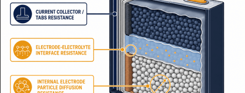
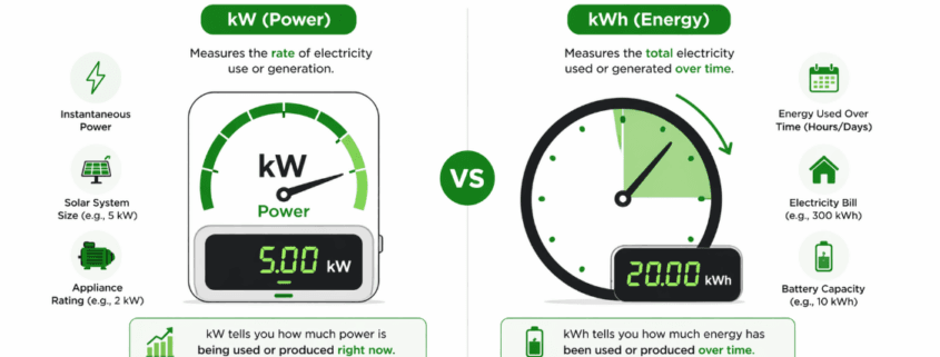
Every lithium-ion cell acts like a small resistor. It sits in series with an ideal voltage source. So when current flows, part of the cell’s energy turns into heat. It never reaches the terminals as usable power. This loss is called cell internal resistance, or Cell IR for short.
Cell IR is not one single part. Instead, it is a combined value. It captures several resistive and electrochemical processes happening at once. As a result, Cell IR changes with temperature, state of charge (SOC), and age. In fact, this is also why two test methods, ACIR and DCIR, can report different numbers for the same cell.
Current-collector foils, tabs, weld joints, separator, and electrolyte conductivity — a true, frequency-independent resistance
Instantaneous; measured directly by 1 kHz ACIR
Charge-transfer (activation) polarization
The energy barrier lithium ions must overcome to cross the electrode–electrolyte interface
Milliseconds to seconds into a current pulse
Diffusion (concentration) polarization
Ion movement and concentration gradients inside the solid electrode particles and electrolyte
Seconds to minutes; dominant during sustained load
Ohmic resistance responds right away. Diffusion resistance, by contrast, builds up slowly over time. So the length of the test pulse changes what you actually measure. That, in short, is why a 1 kHz ACIR reading and a multi-second DCIR pulse test rarely agree on the same cell.
Key Takeaways: Cell Internal Resistance at a Glance
Attribute
Summary
Typical unit
Milliohms (mΩ) for large-format cells; the value scales with electrode/tab area, so small cylindrical cells read much higher than large prismatic cells
Large-format LFP prismatic cells (280–314 Ah)
Commonly 0.15–0.5 mΩ ACIR at 1 kHz, 25 °C, ~30% SOC, varying by manufacturer and grade
Primary heat mechanism
Joule heating, P = I²R — heat rises with the square of current
Rises with
Cell aging/cycling, cold temperature, and SOC extremes (very low or very high)
Lowest at
Mid-range SOC (roughly 30–70%) and moderate temperature (roughly 15–35 °C)
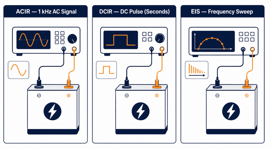
Standard measurement methods
ACIR (1 kHz AC), DCIR (DC pulse), EIS (frequency sweep)
Cell IR is the main source of heat inside an operating cell. Heat generation follows Joule’s law: P = I²R. In other words, heat rises with the square of current. So, even a small increase in resistance causes a large rise in thermal load at high C-rates. That is why, in practice, BESS designers usually size cooling systems around worst-case DCIR rather than nameplate ACIR.
2. Cell IR and Round-Trip Efficiency
Every milliohm of resistance turns some charge and discharge energy into waste heat. This happens instead of usable throughput. Consequently, this resistive loss is one of the main contributors to round-trip efficiency. It sits alongside power-conversion and thermal-management losses.
3. Cell IR, Available Power, and Voltage Sag
Under high current draw, resistance causes the terminal voltage to sag below the open-circuit voltage. If resistance is high enough, that sag can push the terminal voltage below an inverter’s cutoff threshold. This can happen even while real charge remains in the cell. In practice, then, it is a nuisance trip that looks like a capacity problem. In fact, it is a resistance problem.
4. Cell IR as a Leading Indicator of Aging
Cell IR, particularly DCIR, tends to rise before rated capacity visibly degrades. As the solid-electrolyte interphase (SEI) layer thickens with cycling, resistance climbs steadily. For this reason, resistance tracking is a standard input to State of Health (SOH) estimation.
What Changes Cell Internal Resistance
Cell IR is not a fixed number on a datasheet. Instead, it is a dynamic value that shifts with operating conditions. So, the factors below explain most of the variation seen in the field.
Factor
Effect on Internal Resistance
Temperature
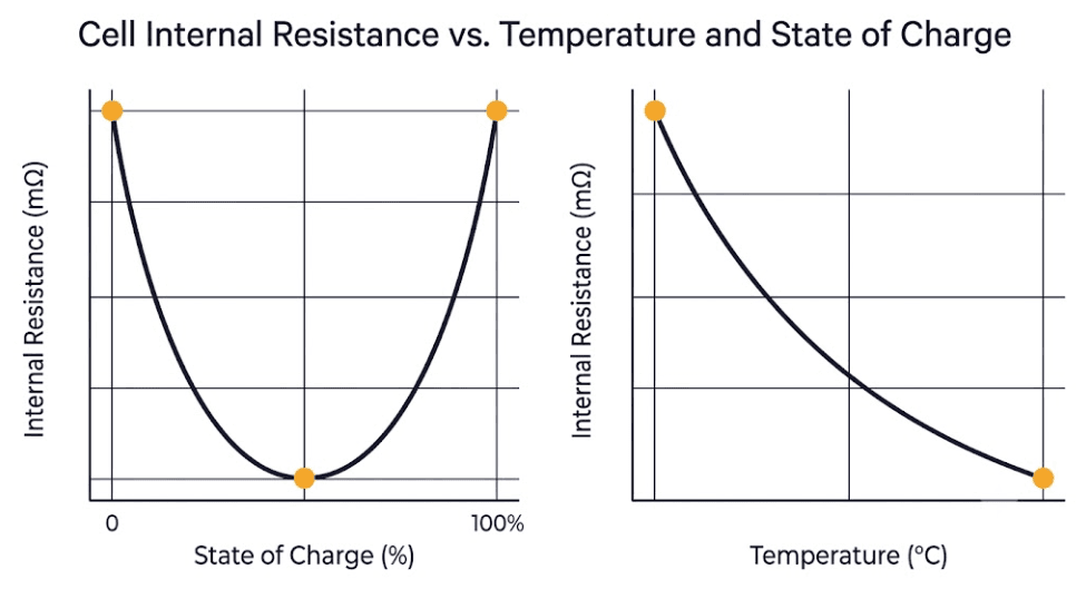
Resistance falls as temperature rises (faster ion mobility) and climbs sharply below roughly 0 °C; temperature swings of ±10 °C can shift measured resistance by around 20%
State of charge (SOC)
Follows a U-shaped curve — lowest in the mid-SOC range, rising again at very high and especially very low SOC as diffusion polarization increases
Aging / cycle count
Rises steadily over cell life as the SEI layer thickens and active material loses contact; DCIR growth of roughly 50–150% over a cell’s usable life is commonly reported, with LFP tending to show faster proportional resistance growth than NMC
C-rate / pulse duration
Longer, higher-current pulses capture more diffusion polarization, so DCIR measured over several seconds reads higher than a short 1 kHz ACIR snapshot on the same cell
Cell format and design
Large-format prismatic and pouch cells generally report lower resistance per cell than small cylindrical formats, because tab and current-collector area — not just chemistry — governs the ohmic term
Manufacturing quality / grade
Electrode coating uniformity, electrolyte wetting, and weld quality all shift the ohmic term; grading by resistance is a standard incoming-QC step for large-format LFP cells
#image_title
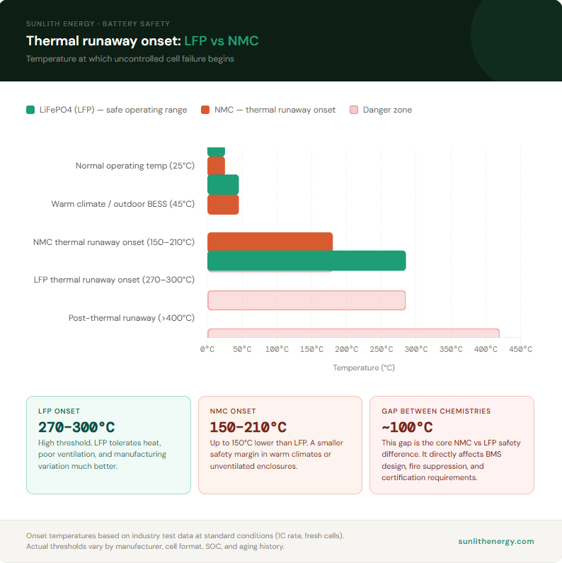
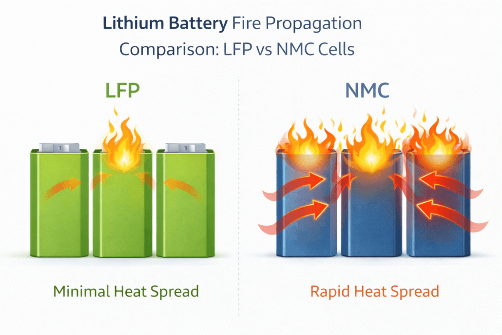
Cell Internal Resistance: LFP vs. Other Chemistries
Lithium iron phosphate (LFP) cells usually start life with low, stable resistance. This is true compared with nickel-based chemistries. In fact, it is one reason LFP has become the default choice for stationary BESS. However, field research on LFP cell aging shows resistance growth speeds up faster, in relative terms, than in NMC cells as cycling progresses. As a result, resistance trending is a more important monitoring parameter for LFP-based systems over a 10–15 year project life. For a full chemistry-level safety comparison, meanwhile, see NMC Battery vs LFP Safety: The Complete BESS Risk Breakdown.
How Cell Internal Resistance Is Measured
Three methods dominate industrial and BESS-integrator practice. Each one, however, answers a slightly different question. So this section compares all three, to help you choose the right one.
Method
Signal Type
What It Captures
Typical Use
ACIR
Small AC current at 1 kHz
Ohmic resistance only — fast, repeatable, standardized
Incoming cell QC, sorting, and grading
DCIR
DC current step or pulse (seconds)
Ohmic + charge-transfer + diffusion polarization together
System-level power modeling, thermal design, real-world performance
EIS
AC sweep from mHz to tens of kHz
Separates all three components individually across frequency
ACIR is fast, taking under a second per cell. It is also highly repeatable. For this reason, it is the standard tool for grading incoming cells at the factory. DCIR, on the other hand, takes longer. But it reflects how a cell actually behaves under a real grid-power pulse. Therefore, it is the preferred input for thermal and power-delivery modeling, as Keysight’s ACIR and DCIR measurement methodology explains. EIS, meanwhile, is the slowest and most instrument-intensive method. So it is reserved for diagnostic work, where engineers need to know exactly which resistance component is degrading.
Cells assembled into a series string should be matched on capacity and open-circuit voltage. However, they should also be matched on Cell IR. A cell with much higher resistance than its neighbors heats faster and sags further under load. It also drifts out of SOC balance faster. This, in turn, speeds up imbalance, even when the BMS works correctly.
Cell IR and Thermal Design Margin
Heat scales with resistance and the square of current. Therefore, thermal designers size cooling capacity around worst-case DCIR at end-of-life, not fresh-cell ACIR. Ignoring resistance growth over the warranty period, unfortunately, is a common cause of undersized thermal margin in early-life system designs.
SOH Estimation and Voltage-Sag Protection
DCIR climbs in a predictable way with age. Because of this, it is one of the standard inputs a BMS uses to estimate State of Health without a full capacity test. Resistance data, in addition, informs voltage-sag-aware cutoff thresholds. In turn, this prevents the BMS from tripping early on a cell that still has usable charge but momentarily high resistance under load.
Frequently Asked Questions
What is a normal cell internal resistance for a LiFePO4 cell?
It depends heavily on cell size. Large-format prismatic LFP cells used in BESS (280–314 Ah) typically measure around 0.15–0.5 mΩ ACIR at 25 °C and roughly 30% SOC. This, of course, varies by manufacturer and grade. Smaller cylindrical LFP cells, by contrast, have much less current-collector and tab area. So they commonly measure in the tens of milliohms.
Does cell internal resistance always increase with age?
In normal operation, yes. Resistance trends upward over a cell’s cycle life as the SEI layer thickens and internal contact degrades. However, the rate varies by chemistry, temperature history, and depth of discharge. Notably, a sudden, sharp resistance spike, rather than a gradual trend, is more likely to signal a fault than normal aging.
Why does Cell IR increase in cold weather?
Low temperature slows lithium-ion movement in the electrolyte. It also slows the electrochemical reactions at the electrode surface. Together, these effects raise both the ohmic and polarization parts of resistance. This is why cold-climate BESS enclosures use insulation and heating elements. As a result, cells stay within their optimal temperature band before drawing high power.
Is lower resistance always better?
Lower resistance generally means less heat, higher efficiency, and more available power. However, resistance is only one design variable among several. Some manufacturers, in fact, accept a modest resistance trade-off for a formulation that prioritizes thermal stability or cycle life. Overall, then, resistance should be evaluated alongside safety margin and cycle-life data, not in isolation.
Is ACIR or DCIR more accurate?
Neither is universally more accurate; they simply answer different questions. ACIR is the more repeatable, standardized snapshot of ohmic resistance. So it works best for comparing cells to each other. DCIR, on the other hand, reflects how the cell behaves under an actual power pulse. This, in turn, makes it the better input for system-level thermal and performance modeling.
The BESS PCS — Power Conversion System — converts DC battery power to AC for loads or the grid. However, what a PCS must do beyond that basic job changes completely depending on the application. Consequently, choosing the wrong PCS type is one of the most expensive mistakes a project team can make.
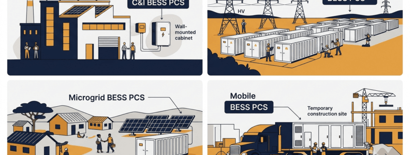
Consider four scenarios. A factory running peak shaving needs a PCS that switches to backup mode within 20 ms. By contrast, a 200 MW grid project needs sub-200 ms frequency response and reactive power control. An island microgrid, meanwhile, needs the PCS to synthesise the AC voltage reference — because no utility connection exists at all. Finally, a mobile BESS on a trailer needs ruggedness and fast site commissioning above all else.
Therefore, this guide covers each of the four application types in detail. Furthermore, it includes a master comparison table so you can see exactly which PCS functions are mandatory, optional, or not needed for each system type. By the end, you will have a clear framework for evaluating any BESS PCS proposal.
What Is a BESS PCS?
Inside every battery energy storage system, the Power Conversion System converts DC from the battery cells to AC for loads or the grid. During charging, it reverses direction and converts AC back to DC. Crucially, both functions share a single hardware platform — hence the term bidirectional.
As Sunlith’s PCS vs. Inverter guide explains, a PCS includes far more than just a bidirectional inverter. In addition, it handles reactive power control, protection functions, grid synchronisation, and communication with the BMS and EMS. According to NREL’s Power Electronics research, the PCS is one of the most critical components in grid-connected storage — because its control functions directly determine grid stability and service quality.
Moreover, the Bidirectional Inverter vs PCS comparison on this site highlights PCS-specific capabilities — including multi-port DC support, islanding, and black start. None of these are available in a stand-alone inverter. However, which of these capabilities you actually need depends entirely on your application type.
Four Application Types at a Glance
Before diving into each type, here is a quick overview showing how the four BESS application categories differ in their primary PCS priorities.
System Type
Typical Power
Grid Connection
Primary PCS Priority
C&I (Behind-the-Meter)
30 kW – 2 MW
Grid-connected, LV/MV
Peak shaving, backup power, solar integration
Utility Scale (Front-of-Meter)
2 MW – 500 MW+
Grid-connected, MV/HV
FFR, reactive power, grid code compliance
Microgrid / Off-Grid
10 kW – 50 MW
Islanded or weak grid
Grid-forming, black start, load following
Mobile BESS
50 kW – 5 MW
Temporary grid or off-grid
Portability, ruggedness, fast commissioning
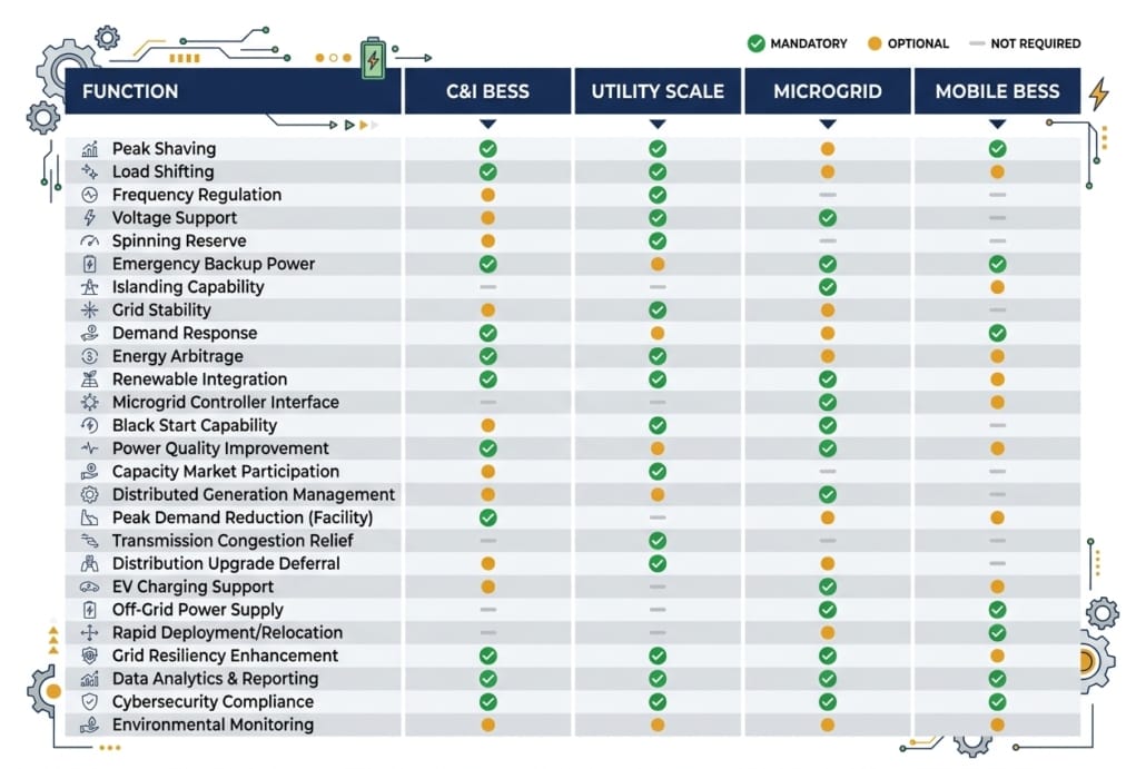
Master Comparison Table: BESS PCS Functions by Application Type
Use this table to compare PCS requirements across all four system types. Functions marked ✔ Mandatory must be specified and tested. Those marked ◉ Optional are recommended in certain site conditions. Those marked ✘ Not Required are not applicable to that system type.
PCS Function / Feature
C&I BESS
Utility Scale
Microgrid / Off-Grid
Mobile BESS
Bidirectional AC-DC Conversion
✔ Mandatory
✔ Mandatory
✔ Mandatory
✔ Mandatory
Peak Shaving / Load Shifting
✔ Mandatory
✘ Not Required
✘ Not Required
◉ Optional
Seamless Transfer / UPS Mode
✔ Mandatory
✘ Not Required
✔ Mandatory
✔ Mandatory
Solar PV Integration (AC/DC)
✔ Mandatory
◉ Optional
✔ Mandatory
◉ Optional
Fast Frequency Response (FFR)
✘ Not Required
✔ Mandatory
✘ Not Required
✘ Not Required
Primary Frequency Response (PFR)
✘ Not Required
✔ Mandatory
◉ Optional
✘ Not Required
Reactive Power (Q) Control
◉ Optional
✔ Mandatory
◉ Optional
✘ Not Required
LVRT / HVRT (Ride-Through)
◉ Optional
✔ Mandatory
✘ Not Required
◉ Optional
Grid-Following Mode (GFL)
✔ Mandatory
✔ Mandatory
◉ Optional
✔ Mandatory
Grid-Forming Mode (GFM)
✘ Not Required
◉ Recommended
✔ Critical
◉ Optional
Black Start Capability
✘ Not Required
◉ Optional
✔ Critical
◉ Optional
Droop Control
✘ Not Required
◉ Optional
✔ Critical
◉ Optional
Load Following
✘ Not Required
✘ Not Required
✔ Critical
◉ Optional
Genset Synchronisation
✘ Not Required
✘ Not Required
✔ Critical
✔ Mandatory
Time-of-Use (TOU) Scheduling
✔ Mandatory
✘ Not Required
✘ Not Required
◉ Optional
Multi-Port DC Input (PV + Battery)
◉ Optional
✘ Not Required
✔ Mandatory
◉ Optional
IEC 61850 / SCADA Integration
✘ Not Required
✔ Mandatory
◉ Optional
✘ Not Required
Modbus TCP / EMS Communication
✔ Mandatory
✔ Mandatory
✔ Mandatory
✔ Mandatory
Wide DC Input Voltage Range
✘ Not Required
✘ Not Required
✔ Mandatory
✔ Mandatory
Overload Capability (150–200%)
✘ Not Required
✘ Not Required
✔ Critical
✔ Mandatory
Compact / Trailer-Mount Design
✘ Not Required
✘ Not Required
✘ Not Required
✔ Critical
Rapid Commissioning (< 4 hrs)
✘ Not Required
✘ Not Required
✘ Not Required
✔ Critical
IP55+ Outdoor Enclosure
◉ Optional
✔ Mandatory
✔ Mandatory
✔ Critical
Noise Level < 65 dB(A)
✔ Mandatory
✘ Not Required
◉ Optional
◉ Optional
NERC CIP / Cybersecurity
✘ Not Required
✔ Mandatory
✘ Not Required
✘ Not Required
Legend: ✔ Mandatory = must be specified and verified at FAT | ◉ Optional = recommended for certain conditions | ✘ Not Required = not applicable
Which PCS functions are mandatory, optional, or not needed? This comparison covers all four BESS application types in one quick-reference chart.
C&I BESS PCS Functions and Features
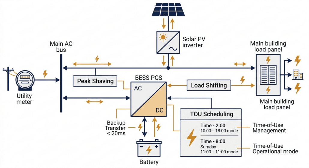
A C&I — Commercial and Industrial — BESS sits behind the utility meter, serving loads inside a building or factory. Unlike utility systems, its PCS does not need to meet grid operator mandates. Instead, it must respond to site-level conditions to deliver financial returns. Specifically, the financial case comes from cutting demand charges, shifting energy to cheap tariff windows, and providing backup power during outages.
In a C&I system, the PCS manages power flow between the utility meter, solar array, and site loads — all simultaneously.
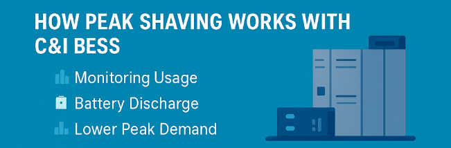
Peak Shaving and Time-of-Use Scheduling
Peak shaving is the most financially important C&I BESS PCS function. Demand charges can account for 30–50% of a commercial electricity bill. Therefore, the PCS charges the battery during low-demand periods and then discharges during peak demand to reduce the demand reading at the meter. Furthermore, time-of-use (TOU) scheduling shifts energy consumption into cheaper tariff windows, reducing energy cost on top of the demand saving.
Both functions require the PCS to support scheduled cycles via the EMS. Additionally, the PCS must respond to dynamic tariff signals from the utility in real time. As the IEA’s Grid-Scale Storage report notes, demand-side flexibility is one of the fastest-growing commercial storage applications globally. Consequently, TOU scheduling is now a baseline requirement in most C&I BESS tenders.
Seamless Transfer and Backup Power
When the grid fails, the C&I BESS PCS must switch to island mode fast enough to protect sensitive equipment. This transfer — called a seamless transfer or UPS mode — must complete within 20 ms for most commercial sites, and within 10 ms for data centres or precision manufacturing. Critically, seamless transfer is not a standard feature on all PCS products, so buyers must list the maximum allowed transfer time explicitly in their specification.
Furthermore, the PCS must be able to supply the full site load in island mode — not just a fraction of it. Therefore, both the transfer time and the island-mode power rating must be tested during factory acceptance testing (FAT). Accepting a vendor declaration without live testing is a common and expensive commissioning mistake.
Solar PV Integration
Most C&I BESS projects include rooftop or carport solar PV, so the PCS must integrate with the solar inverter. Two integration methods are available. AC coupling connects the solar inverter and PCS on the same AC bus — straightforward to retrofit, though energy passes through two conversion stages, which adds losses. DC coupling, by contrast, connects solar panels directly to the BESS DC bus via a DC-DC converter inside the PCS. This cuts conversion losses significantly. However, DC coupling requires the PCS to support multi-port DC input, so buyers must specify this feature explicitly at procurement stage.
C&I PCS Key Specifications
Power Range: 30 kW – 2 MW continuous output
Seamless Transfer: < 20 ms to island mode (< 10 ms for critical loads)
TOU Scheduling: Via EMS with dynamic tariff integration
Solar Integration: AC-coupled or DC-coupled PV input support
Grid Code: IEEE 1547 / UL 1741-SA for LV interconnection
Noise: < 65 dB(A) at 1 m for indoor installations
Communications: Modbus TCP to site EMS or BMS
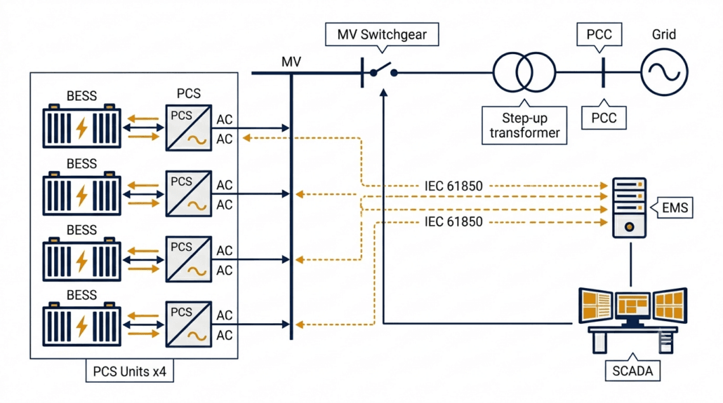
Utility Scale BESS PCS Functions and Features
A utility-scale BESS connects to the medium or high-voltage grid in front of the meter. Consequently, its PCS must comply with grid operator requirements — legal obligations rather than performance suggestions. These requirements are more precise, more rigorously enforced, and technically more demanding than anything a C&I project faces. Therefore, a utility-scale PCS is a genuinely different machine from a C&I unit, even if the basic conversion function is the same.
At utility scale, multiple PCS units run in parallel, feeding through a step-up transformer to the grid, with full IEC 61850 SCADA integration.
Fast Frequency Response (FFR)
FFR is the most commercially valuable utility-scale PCS function. When grid frequency drops — for example, because a large generator trips — the PCS must detect the deviation and ramp power within milliseconds. Most grid operators set the response window at 200 ms. However, some markets require 150 ms, and AEMO in Australia now tenders for sub-100 ms response.
To achieve these targets, the PCS control loop must use a dedicated high-speed frequency measurement algorithm — standard power quality meters are far too slow. Furthermore, the EMS-to-PCS communication link must have a round-trip latency below 50 ms, otherwise the communication delay consumes the available response window before the PCS even starts ramping. According to the US Department of Energy Energy Storage Grand Challenge, fast-responding battery storage is central to grid stability as thermal generation retires. Consequently, FFR is now a baseline commercial requirement for most utility-scale BESS contracts.
Reactive Power Control
Utility-scale BESS must provide reactive power — VAR — support to the grid. Under IEEE 1547-2018 in North America and EN 50549 in Europe, this function is mandatory. Specifically, the PCS must inject or absorb reactive power across all four quadrants of the PQ operating plane.
One critical detail: the PCS must deliver Q control even when the battery is at minimum state of charge — a requirement known as Q-at-night capability. Notably, some PCS products restrict reactive power output when the battery is in standby. Therefore, buyers must test Q-at-zero-kW operation during commissioning rather than rely on a datasheet claim alone.
Voltage Ride-Through: LVRT and HVRT
Grid codes require BESS to stay connected during voltage disturbances. LVRT — Low Voltage Ride-Through — means the PCS holds its grid connection during faults and injects reactive current to support the network voltage. According to ENTSO-E’s Network Code on Requirements for Generators, LVRT capability must extend down to 15% of nominal voltage for up to 625 ms. HVRT works in reverse — the PCS stays connected and absorbs reactive power during grid over-voltages.
Together, LVRT and HVRT define the voltage operating envelope of the PCS. Buyers must obtain the full voltage-time profile from the vendor and then verify it against the grid code at their specific point of interconnection. Requirements vary by country and operator, so this step cannot be skipped.
Grid-Following vs Grid-Forming at Utility Scale
Most utility-scale PCS units operate in grid-following (GFL) mode — synchronising to the grid via a Phase-Locked Loop and injecting current according to EMS setpoints. GFL works well on strong grids. However, as renewable penetration increases, grids are weakening and GFM capability is becoming more important.
Grid-forming (GFM) mode provides better fault current support and voltage stability on weak grids. As Sunlith’s Microgrid BESS technical guide notes, Australia already had over 1,070 MW of grid-forming BESS deployed by mid-2025. Therefore, GFM is mainstream technology, and buyers of utility-scale systems in high-renewable regions should evaluate it seriously.
Utility Scale PCS Key Specifications
FFR Latency: < 150–200 ms from event to ramp start
Q Control: Four-quadrant reactive power at all SOC levels including zero kW
LVRT / HVRT: Must match grid code voltage-time profile at PCC
DC Voltage: 1,000 V or 1,500 V DC to reduce cabling losses at scale
Communications: IEC 61850 GOOSE for deterministic low-latency dispatch
Cybersecurity: NERC CIP (North America) or IEC 62351 encryption
Certifications: IEEE 1547, EN 50549, AS/NZS 4777, UL 1741-SA — market-dependent
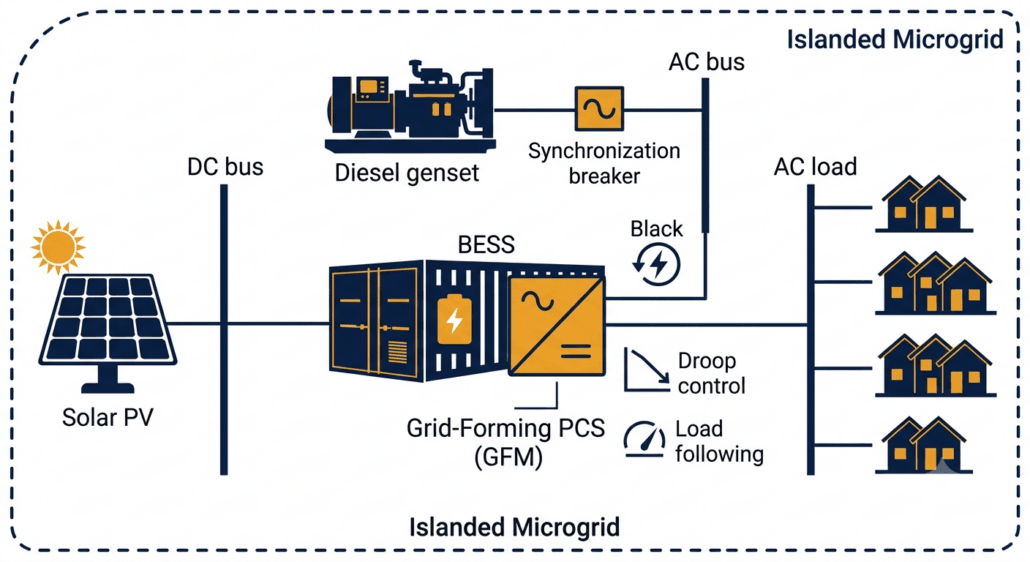
Microgrid and Off-Grid BESS PCS Functions and Features
Among all four application types, an off-grid or islanded microgrid BESS places the most demanding requirements on the PCS. No utility grid exists to act as a voltage and frequency reference. Consequently, the PCS must create that reference entirely from battery power. This changes nearly everything about how the system operates — from the control architecture down to the protection coordination.
In an off-grid microgrid, the BESS PCS synthesises the local AC voltage and frequency from scratch — with no utility connection to lean on.
Grid-Forming Mode: The Non-Negotiable Requirement
Grid-forming (GFM) mode is the single most important requirement for any off-grid BESS PCS. Without it, the system simply cannot operate in an islanded environment. In GFM mode, the PCS synthesises the local AC voltage and frequency directly from battery DC power. All other devices in the microgrid — solar inverters, gensets, loads — then lock onto the PCS output as their grid reference.
This role is fundamentally different from a grid-connected system, where the PCS follows an existing grid reference. Consequently, GFM requires a completely different control architecture — it is not simply a software switch added to a grid-following PCS. Therefore, buyers must verify GFM certification through independent testing, not just through a vendor’s datasheet claim.
Black Start
Black start is the ability to energise a completely dead AC network from battery power alone, starting from zero volts. This function is essential for off-grid sites and increasingly mandatory for grid-scale microgrid contracts. However, it is also one of the most commonly missing features in PCS datasheets.
Specifically, black start requires the PCS to ramp up the AC bus voltage gradually — from zero — then connect loads in sequence as the voltage stabilises. Furthermore, close coordination with the protection scheme is needed to prevent fault currents during energisation. Therefore, black start must be tested and verified during commissioning. Listing it in a specification without on-site validation is not sufficient.
Droop Control and Load Following
In an islanded system, loads shift constantly and there is no external grid to absorb imbalances. Therefore, the PCS must continuously match its output to the instantaneous load demand — a function called load following. Droop control is closely related: it allows the PCS to share load automatically with a genset or another BESS unit by adjusting output in proportion to frequency or voltage deviations, without waiting for a central EMS command.
Consequently, droop control improves microgrid stability and allows multi-source systems to operate reliably even when the EMS communication link is temporarily lost. For these reasons, droop control and load following are both marked as critical requirements in the master comparison table above.
Genset Synchronisation
Many microgrids include a diesel or gas genset as a backup source. Before the interconnecting breaker closes, the BESS PCS must synchronise its output voltage with the genset — matching frequency, phase, and amplitude. Without proper synchronisation, inrush currents and voltage transients can damage both the PCS and the genset. Moreover, the PCS must manage transitions smoothly in both directions: when the genset starts up and when it shuts down.
Microgrid PCS Key Specifications
Grid-Forming Mode: Mandatory — PCS must synthesise local AC voltage and frequency
Black Start: Must be tested and certified on-site, not just listed in a datasheet
Droop Control: Autonomous load sharing without relying on EMS command
Load Following: Fast response to sudden load steps — no external grid buffer
Genset Sync: Smooth breaker closure with diesel or gas generators
Seamless Transfer: < 10 ms for critical load protection in island mode
Overload: 150–200% of rated current for 10 s to handle motor start loads
DC Voltage Range: Wide window to handle SOC swings without derating in island mode
Mobile BESS PCS Functions and Features
Mobile BESS units are trailer-mounted or containerised storage systems that travel between sites. Common applications include event venues, construction sites, disaster relief operations, emergency grid backup, and temporary peak demand support. Unlike fixed installations, however, mobile BESS PCS units must prioritise three things above all else: portability, ruggedness, and speed of deployment.
Mobile BESS units must reach full power output within hours of arriving on site — which demands a compact, rugged PCS with fast commissioning and multi-source compatibility.
Compact Design and High Power Density
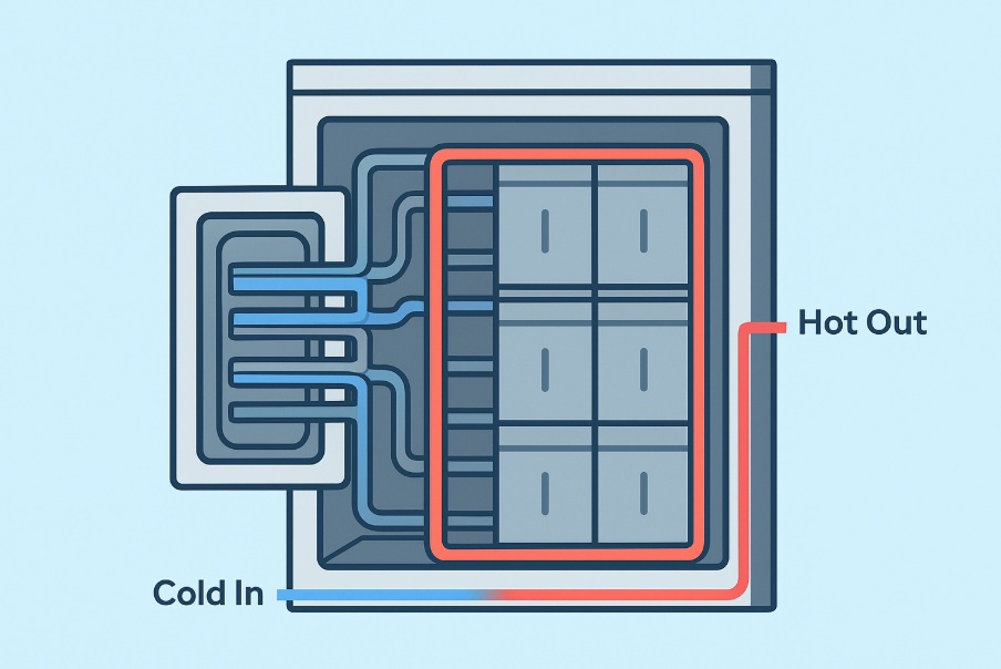
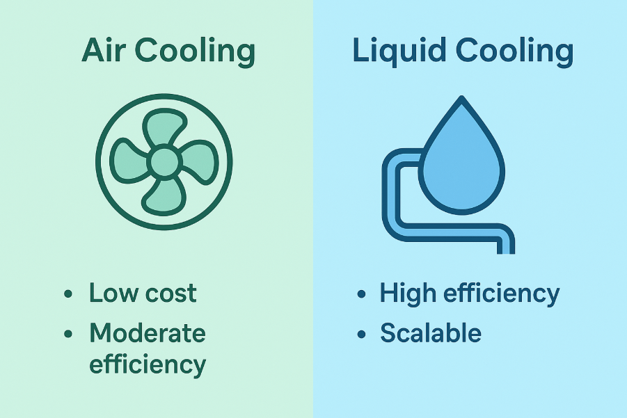
Above all, a mobile BESS PCS must fit inside a trailer or small container. For this reason, power density is the primary design constraint — and liquid-cooled PCS units are preferred above 200 kW because they deliver more power per cubic metre and generate significantly less noise than air-cooled equivalents. Additionally, the PCS must tolerate vibration and shock loads during road transport, which standard stationary units are simply not designed to handle.
Rapid Site Commissioning
Speed of deployment is what sets mobile BESS apart from every other application type. A mobile BESS must reach full power output within a few hours of arriving on site — not the multi-week integration process typical of a permanent installation. Therefore, the PCS must support plug-and-play commissioning: pre-configured protection settings, automatic detection of local grid frequency (50 Hz or 60 Hz), and simple plug-in connections for power and communications.
Furthermore, the PCS must support multiple connection scenarios out of the box — temporary grid connection, islanded operation with a genset, or fully standalone off-grid mode. Consequently, mobile PCS units must include both grid-following and grid-forming capabilities as standard. Waiting for a firmware upgrade or specialist configuration on-site defeats the purpose of a mobile system.
Genset Integration and Overload Capability
Mobile BESS units frequently operate alongside diesel generators. Therefore, the PCS must synchronise with the genset smoothly and manage load transfers in both directions — when the engine starts and when it shuts down. Additionally, overload capability is a hard requirement for mobile deployments. Motor start loads on construction sites or industrial events can draw 150–200% of steady-state current for several seconds. A PCS that trips under this load makes itself useless.
Rugged Enclosure and Wide Temperature Range
Mobile BESS units deploy in unpredictable environments — muddy construction sites, outdoor festivals, flood-affected areas, and extreme climates. Consequently, the PCS must carry an IP55 or higher enclosure rating to resist dust and water ingress. Furthermore, the operating temperature window must extend well beyond typical stationary limits — many mobile PCS products are rated for operation between -25°C and +55°C and storage down to -40°C.
Mobile BESS PCS Key Specifications
Design: Compact, high power density; liquid cooling preferred above 200 kW
Transport Tolerance: Rated for road vibration and shock per IEC 60068-2
Commissioning Time: < 4 hours from arrival to full power output
Grid Frequency Auto-Detect: 50 Hz / 60 Hz without manual reconfiguration
Operating Modes: Grid-following and grid-forming built in as standard
Genset Sync: Smooth synchronisation and load transfer in both directions
Overload: 150–200% rated current for 10 s minimum
Enclosure: IP55 minimum; IP65 for harsh environments
Temperature Range: -25°C to +55°C operating; -40°C storage
PCS Functions Common to All Four Application Types
While each application type has unique demands, several PCS functions are universal. These baseline capabilities define what a PCS is — regardless of where it is installed or what grid code applies.
Bidirectional DC-AC Power Conversion
Every BESS PCS converts DC to AC during discharge and AC to DC during charging. Modern units reach peak conversion efficiency of 96% to 98.5%. However, round-trip efficiency matters more than peak figures. As Sunlith’s energy storage losses guide explains, power conversion is one of the four main loss categories in any BESS. Even a 1% PCS efficiency improvement compounds significantly across a 15-year project life — so it is worth specifying carefully.
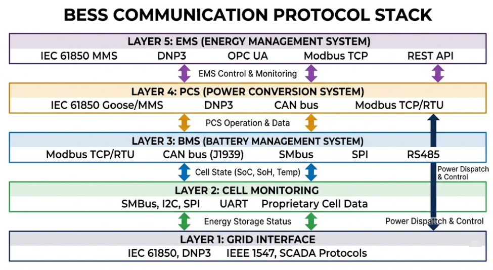
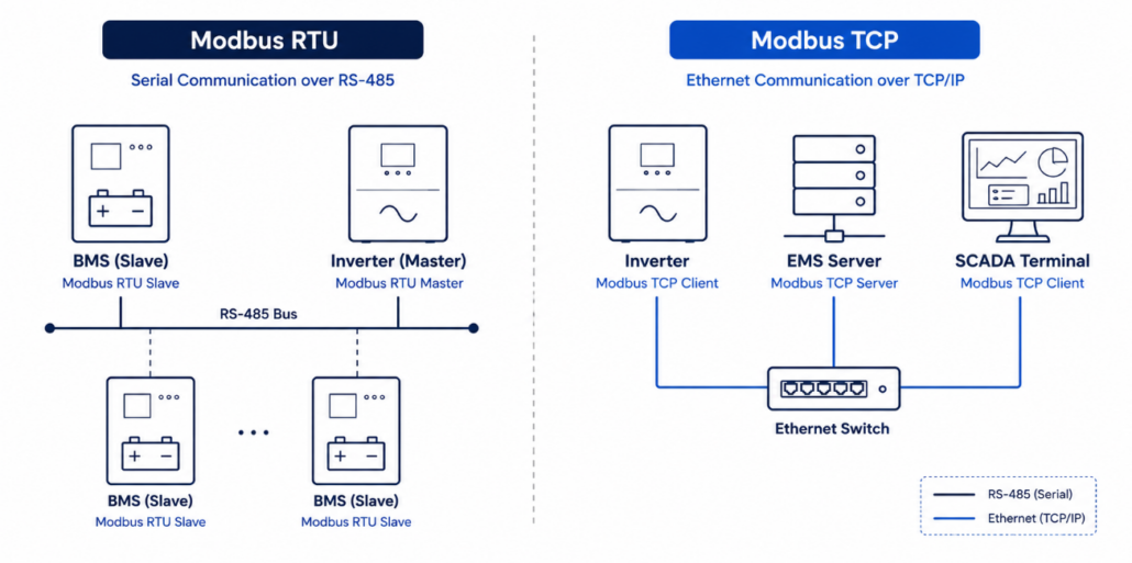
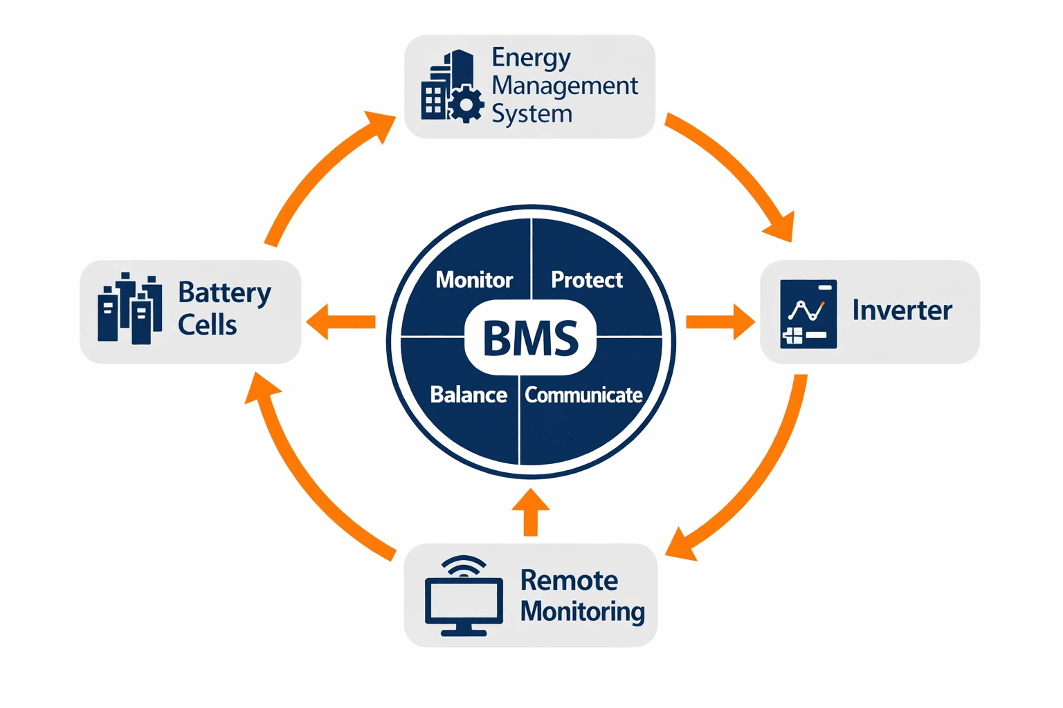
BMS and EMS Communication
Two control layers interface with the PCS. Working from the bottom up: the Battery Management System (BMS) sends real-time charge and discharge limits — maximum current, minimum cell voltage, and thermal boundaries. These limits must always be respected by the PCS, including during high-priority grid response events. Above the BMS sits the Energy Management System (EMS), which sends power setpoints and operating mode commands to the PCS.
As Sunlith’s BESS communication protocols guide explains, the BMS transmits SOC, SOH, cell voltages, temperatures, current, and fault codes to enable safe and optimised dispatch. Consequently, the PCS-BMS-EMS communication stack is not merely a data link — it is a safety-critical control interface that must be validated end-to-end before commissioning.
DC-Side Battery Protection
Regardless of application type, all BESS PCS units must protect the DC bus from electrical faults. Key protection functions include over-current limiting, DC bus voltage regulation, pre-charge control to prevent capacitor inrush, earth fault detection, and short-circuit protection. Together, these functions protect the battery cells and reduce the risk of thermal runaway events. Therefore, buyers should always request the full DC protection relay specification — not just the AC circuit breaker ratings.
Key Technical Features to Specify in Any BESS PCS
Regardless of application type, the parameters below form a baseline specification checklist for any BESS PCS request for proposal (RFP).
Feature
Typical Range
Notes
Rated Power
30 kW – 10 MW per unit
Confirm continuous rating — not peak or 30-second duty
DC Voltage Range
600 V – 1,500 V DC
Must cover full battery SOC range without derating
AC Output Voltage
400 V / 690 V / 11 kV
MV output reduces transformer count at utility scale
Peak Efficiency
97% – 98.5%
Also request weighted average at your load profile
Power Factor Range
0.8 lead – 0.8 lag
Confirm Q capability at zero kW active output
FFR Response Time
< 100 – 200 ms
Verify against grid code at interconnection point
Grid-Forming Mode
Mandatory (microgrid)
Optional at utility scale; essential for off-grid
Seamless Transfer
< 20 ms C&I; < 10 ms off-grid
Test at FAT — do not accept a datasheet figure only
Communications
Modbus TCP / IEC 61850
IEC 61850 GOOSE for FFR; Modbus TCP for C&I dispatch
Certifications
IEEE 1547, UL 1741-SA, EN 50549
Request current certificates with expiry dates
Cooling
Forced air / Liquid-cooled
Liquid cooling preferred above 500 kW
Enclosure Rating
IP54 indoor; IP55+ outdoor
IP65 for mobile or harsh-environment sites
Warranty
5 – 10 years
Align with BESS project life of 15–20 years minimum
Relevant Standards for BESS PCS
Standards differ by region and application type. Always verify that certifications are current, geographically valid, and cover the specific grid code version in force at your interconnection point. Furthermore, check expiry dates — expired certifications are a common and avoidable cause of project delays.
Use this checklist when writing a BESS PCS request for proposal (RFP). Start with the application type — it determines which items below are mandatory.
Define application type: C&I, utility, microgrid, or mobile. This single decision shapes every other requirement.
Rated Power: Specify continuous AC output (kW) and DC input separately — not peak ratings.
DC Voltage Window: Confirm the PCS operates across the full battery SOC range without derating at either end.
Efficiency Curve: Request weighted average efficiency at your typical daily load profile, not only the nameplate peak value.
Grid-Forming Mode: Mandatory for microgrid. Specify if needed for weak-grid or mobile deployments.
Seamless Transfer Time: < 20 ms for C&I; < 10 ms for off-grid critical loads. Test at FAT without exception.
FFR Response Time: Define maximum latency from EMS setpoint to output ramp start — applicable to utility scale only.
Reactive Power: Specify power factor range. Confirm Q control works at zero kW active power output.
Black Start: Specify explicitly if required — not included in all PCS products. Test on-site.
Overload Capability: 150–200% rated current for 10 s — mandatory for microgrid and mobile types.
Commissioning Time: < 4 hours from arrival to full output — applicable to mobile BESS deployments.
Communications: Specify Modbus TCP, IEC 61850 GOOSE, or CAN Bus as required for your application.
Certifications: List required standards by jurisdiction. Request current certificates with expiry dates.
Enclosure Rating: IP54 for indoor; IP55+ for outdoor; IP65 for mobile or harsh-environment sites.
Inside a battery energy storage system, the Power Conversion System converts DC electricity from the battery to AC for loads or the grid. During charging, it reverses and converts AC to DC. Beyond this basic function, it also controls reactive power, responds to grid frequency and voltage events, and protects the battery. In off-grid systems, furthermore, it synthesises the local AC voltage and frequency reference from battery power alone.
Are C&I and utility scale BESS PCS units the same product?
No — they are significantly different. A C&I PCS focuses on peak shaving, load shifting, solar integration, and fast backup transfer. A utility-scale PCS, by contrast, must meet strict grid code requirements for FFR, reactive power control, and voltage ride-through. Consequently, you cannot simply scale up a C&I PCS for a utility project — the control architecture, communications, and certification requirements are fundamentally different.
Does an off-grid microgrid need a different PCS?
Yes, absolutely. A microgrid BESS PCS must operate in grid-forming mode — synthesising the local AC voltage and frequency without any external grid connection. In addition, it must support black start, droop control, load following, and genset synchronisation. None of these are required in most grid-connected applications. Therefore, always specify off-grid requirements explicitly in procurement documents — do not assume they are included.
What makes a mobile BESS PCS different from a fixed installation?
A mobile BESS PCS must be compact, transport-rated, and fast to commission on arrival. It must auto-detect local grid frequency and support both grid-following and grid-forming modes as standard. Furthermore, it must tolerate road vibration, wide temperature ranges, and variable site conditions that a stationary unit would never encounter. Consequently, mobile PCS units are a distinct product category — not simply a stationary PCS mounted on a trailer.
What efficiency should I expect from a BESS PCS?
Modern BESS PCS units reach peak efficiency of 97% to 98.5%. However, weighted average efficiency across a typical daily profile runs 1–2% lower than the peak figure. Therefore, always request the weighted average efficiency for your specific load profile — the nameplate peak value alone is not a reliable basis for energy yield calculations.
Which standards does a BESS PCS need?
Certification requirements depend on your project location and application type. In the US, IEEE 1547-2018 and UL 1741-SA are typically required. Meanwhile, Europe relies on the EN 50549 standard. For projects in Australia, AS/NZS 4777 is mandatory. Additionally, utility-scale projects in North America must meet NERC CIP cybersecurity requirements. See Sunlith’s Worldwide PCS Certification Guide for full details by country.
How Sunlith Energy Approaches BESS PCS Selection
At Sunlith Energy, we treat the PCS as one of the most important decisions in any energy storage project. Every engagement begins with an application analysis that defines the required operating modes, protection settings, and grid code obligations for that specific site. Furthermore, we verify certifications independently — rather than accepting vendor declarations without review.
Our team has evaluated PCS products across C&I, utility, microgrid, and mobile deployments. Importantly, we carry out PCS-EMS-BMS integration testing before any system leaves the factory. This ensures that communication protocols, protection coordination, and control modes are all validated end-to-end. Consequently, our clients avoid the costly commissioning surprises that arise when integration is left to the site team.
Contact the Sunlith Energy team if your project needs a BESS PCS specification review, vendor proposal evaluation, or commissioning support.
Selecting the right BESS PCS comes down to knowing your application. A C&I system needs peak shaving, backup transfer, and solar integration. A utility-scale project demands FFR, reactive power control, and full grid code compliance. An off-grid microgrid requires grid-forming mode, black start, and droop control. A mobile BESS, moreover, needs ruggedness, fast commissioning, and multi-mode operation out of the box. Therefore, there is no single PCS specification that fits all four scenarios — and trying to use one is a recipe for expensive rework.
Consequently, the first and most important step is to define your application type precisely. From there, use the master comparison table and specification checklists in this guide to build your PCS requirements. Furthermore, involve your PCS vendor early, verify certifications independently, and test all critical functions — especially seamless transfer, black start, and FFR — during factory acceptance testing before the system ships.
Sunlith Energy works with EPCs, project developers, and asset owners across all four BESS application types. Contact our team to discuss PCS requirements for your next project.
Introduction: Why BESS C-Rate Changes Everything About System Price and Performance
Every Battery Energy Storage System (BESS) datasheet carries a C-rate figure. It sits alongside capacity in kWh, chemistry type, and cycle life. Yet the BESS C-rate is almost always the least-explained number on the page — and, in practice, the most consequential one.
Understanding BESS C-rate matters because it governs three things at once. First, it sets how much peak power the system can deliver. Second, it controls how quickly the battery recharges between dispatch events. Third, it predicts how long cells will last under real operating conditions. As a result, BESS C-rate has a direct, measurable effect on installed system cost. In fact, the price gap can be large. Between a 0.5C energy-type system and a 2C power-type system of identical kWh capacity, the difference is often 50 to 100 per cent.
This guide explains the BESS C-rate concept from first principles. It covers both charge and discharge C-rates based on foundational NREL battery storage technology basics with worked examples. It also maps the full relationship between C-rate tier, application, and installed price. By the end, therefore, you can read any BESS datasheet with confidence. You will also be able to compare quotations on a like-for-like basis.
1. What Is BESS C-Rate? Definition, Formula and Notation
BESS C-rate is a standardised measure of how fast a battery is charged or discharged relative to its total storage capacity. The “C” stands for capacity. The number in front of it acts as a multiplier of that capacity.
📐
BESS C-rate formula: C-rate = Current (A) ÷ Nominal Capacity (Ah) Example — 200 Ah LFP battery: • Discharged at 200 A → 1C → full discharge in 1 hour • Discharged at 400 A → 2C → full discharge in 30 minutes • Discharged at 100 A → 0.5C → full discharge in 2 hours
Importantly, BESS C-rate is chemistry-independent and capacity-independent. For example, a 1C discharge of a 10 kWh residential BESS delivers 10 kW. In contrast, a 1C discharge of a 2 MWh grid system delivers 2 MW. In both cases, the rate is relative — it describes discharge speed as a proportion of total storage, regardless of system size.
BESS C-Rate Notation: Reading the Two Datasheet Formats
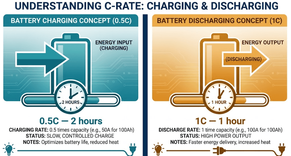
Two notation formats appear on datasheets and both describe the same BESS C-rate value. The multiplier format uses a number before C: 2C means discharge at double the 1-hour rate, giving a full drain in 30 minutes. The fractional format divides capacity: C/2 means discharge at half the 1-hour rate, giving a full drain in 2 hours.
Therefore, C/2 and 0.5C are identical. Similarly, C/10 and 0.1C are identical. When a datasheet shows a charge rate of C/5 alongside a discharge rate of 1C, the system charges five times more slowly than it discharges. As explained in Section 2, this asymmetry is a deliberate engineering choice — not a product limitation.
BESS C-Rate Quick Reference: From 0.1C to 10C
C-Rate
Meaning
Discharge Time
Charge Time (at same rate)
Real-World Parallel
C/10 (0.1C)
Discharge at 1/10th capacity current
10 hours
10 hours
Solar trickle charge / overnight backup reserve
C/5 (0.2C)
Discharge at 1/5th capacity current
5 hours
5 hours
Long-duration island grid storage
C/2 (0.5C)
Discharge at half capacity current
2 hours
2 hours
C&I energy arbitrage, solar self-consumption
1C
Discharge at full capacity current
1 hour
1 hour
Peak shaving, daily cycling BESS
1.5C
Discharge at 1.5× capacity current
40 minutes
—
Aggressive demand charge reduction
2C
Discharge at double capacity current
30 minutes
—
Grid frequency response, EV charging buffer
3C
Discharge at 3× capacity current
20 minutes
—
Fast-response ancillary services
10C
Discharge at 10× capacity current
6 minutes
—
Ultra-fast EV charging, power electronics
2. BESS Charge C-Rate vs Discharge C-Rate: Why the Two Figures Differ
Most explanations of BESS C-rate focus only on discharge — how fast the battery empties. However, charge C-rate is equally important for dispatch planning and cell longevity. In most commercial BESS installations, moreover, the two figures are deliberately set at different levels.
Why BESS Charge C-Rate Must Stay Below Discharge C-Rate
Charging a lithium-ion cell forces lithium ions back into the anode. If this process happens too fast, ions arrive at the anode surface faster than the graphite lattice can absorb them. Consequently, excess lithium deposits as metallic lithium on the surface — a process called lithium plating. Lithium plating is irreversible. It permanently reduces capacity and, in extreme cases, creates internal short circuits that cause thermal runaway.
For this reason, LFP manufacturers specify a maximum continuous charge C-rate that is lower than the discharge limit. The most common commercial BESS pairing — 0.5C charge and 1C discharge — reflects this constraint directly.
⚡
Standard C&I LFP BESS charge vs discharge C-rate: Charge rate: 0.5C → fills in 2 hours → protects anode, maximises cycle life Discharge rate: 1C → empties in 1 hour → delivers full rated peak power This asymmetry is intentional — not a limitation.
The practical implication is straightforward. A 500 kWh / 1C BESS delivers 500 kW to the grid in one hour. However, it needs two hours to recharge at 0.5C. Therefore, always plan your dispatch schedule around the slower charge rate — not just the discharge figure.
BESS Charge C-Rate Worked Examples: 100 Ah LFP Cell
Charge C-Rate
Charge Time (100 Ah cell)
Charge Current
BESS Application
LFP Cell Impact
C/10 (0.1C)
10 hours
10 A
Overnight trickle from small solar array
Excellent — maximum cycle life, zero thermal risk
C/5 (0.2C)
5 hours
20 A
Slow solar charge, low-irradiance days
Excellent — best for calendar longevity
C/2 (0.5C)
2 hours
50 A
Standard C&I BESS grid or solar charge
Very good — recommended daily charge rate for LFP
1C
1 hour
100 A
Fast recharge between morning/afternoon peaks
Good — within spec; monitor cell temperature
2C
30 minutes
200 A
Rapid recharge for EV charging buffer BESS
Moderate — active cooling essential; reduces cycle life
3C+
<20 minutes
300 A+
Ultra-fast charging stations
Risk of lithium plating — requires specialist cells only
BESS Discharge C-Rate Worked Examples: 100 Ah LFP Cell
Discharge C-Rate
Discharge Time (100 Ah)
Power Output
BESS Application
LFP Cell Impact
C/4 (0.25C)
4 hours
25 A
Frequency regulation support, overnight levelling
Excellent — minimal degradation, long cycle life
C/2 (0.5C)
2 hours
50 A
Residential shifting, off-grid night supply
Excellent — standard low-stress operating point
1C
1 hour
100 A
C&I peak shaving (30–60 min demand events)
Very good — standard commercial BESS daily operation
1.5C
40 minutes
150 A
Aggressive demand charge reduction
Good — within LFP spec with adequate thermal management
2C
30 minutes
200 A
Grid frequency regulation, EV buffer discharge
Moderate — higher heat, faster degradation per cycle
10C
6 minutes
1,000 A
EV ultra-fast charging station power burst
Requires high-power LFP or specialist cell chemistry
Full BESS C-Rate Cycle: Real Charge and Discharge Example
To anchor both BESS C-rate concepts in a real project, consider a 500 kWh LFP BESS at a cold-storage facility. The site faces a peak demand charge triggered above 400 kW. Consequently, the system runs two discharge events per day:
NIGHT CHARGE (22:00–00:00) — BESS C-rate: 0.5C, from off-peak grid Current: 408 A | Power: 250 kW | Duration: 2 hours Result: fully charged at midnight using cheap off-peak tariff
MORNING DISCHARGE (08:00–09:00) — BESS C-rate: 1C, peak shaving Current: 815 A | Power: 500 kW | Duration: 1 hour Result: production ramp absorbed; grid import held below 400 kW
AFTERNOON CHARGE (12:00–14:00) — BESS C-rate: 0.5C, from rooftop solar Current: 408 A | Power: 250 kW | Duration: 2 hours Result: battery refilled by solar for the afternoon peak
This 0.5C charge / 1C discharge pattern keeps LFP cells within their optimal BESS C-rate operating window. As a result, cycle life typically exceeds 4,000 full cycles at 80% depth of discharge — sufficient for over 10 years of daily operation.
📌
BESS C-rate rule of thumb: if your system is specified for 1C discharge, plan to charge at 0.5C. If it operates at 2C discharge, confirm that the cell chemistry and BMS support at least 1C charging without lithium plating risk.
3. How the BMS Enforces BESS C-Rate Limits in Real Operation
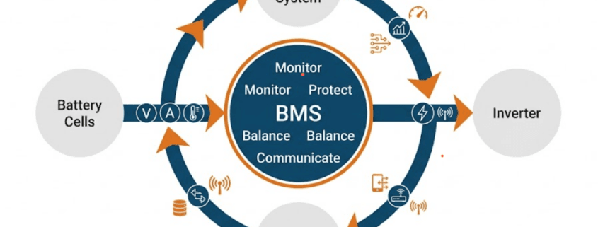
The Battery Management System (BMS) is the component that enforces BESS C-rate limits at the cell level during both charge and discharge. It monitors current, cell temperature, and state of charge (SoC) in real time. Whenever any parameter approaches its safe boundary, the BMS intervenes immediately to protect the cells.
BMS Charge Control: CC/CV Protocol and BESS C-Rate Tapering
During charging, the BMS applies a constant-current / constant-voltage (CC/CV) protocol. The constant-current phase runs at the rated charge C-rate until cell voltage approaches its upper limit. At that point, the BMS transitions to constant-voltage mode and tapers current down to zero as the cell reaches full charge. This taper phase is critical — without it, sustained high-current charging causes the lithium plating described in Section 2.
BMS Discharge Control: BESS C-Rate Curtailment and SoH Tracking
During discharge, the BMS monitors current and cell temperatures continuously. When current exceeds the rated BESS C-rate, the BMS issues a curtailment command within milliseconds. This typically happens because of a load spike or an inverter fault. High-C-rate BESS systems operating at 2C or above require particularly fast BMS response. For this reason, systems designed for sustained 2C operation use BMS platforms with sub-10 ms cell-level sampling. This specification adds cost, but it also prevents thermal cascades.
In addition to real-time protection, the BMS tracks the cumulative effect of each C-rate event on State of Health (SoH). SoH is the ratio of current capacity to the original rated capacity. Understanding what a battery management system (BMS) is and how its topology handles cell balancing during high-discharge events reveals why operating consistently at or below the rated BESS C-rate is one of the most effective ways to preserve SoH while extending your warranty-covered cycle count.
4. How High BESS C-Rate Reduces Usable Capacity: The Rate-Capacity Effect
A battery discharged at a high BESS C-rate typically delivers less total energy than the same battery at a lower rate. This happens even though the nameplate capacity is identical. Consequently, this fact surprises many buyers. It is also one of the most important concepts to understand before specifying a system.
Why BESS C-Rate Affects How Much Energy You Actually Receive
Inside a lithium-ion cell, energy is released as lithium ions migrate from cathode to anode through the electrolyte. This migration has a physical speed limit, set by the ionic conductivity of the electrolyte and the diffusion rate of lithium within the electrode materials.
At low BESS C-rates, ions cross the electrolyte in an orderly process and the full stored capacity is accessible. At high C-rates, however, ions are forced to move faster than the cell structure allows. This causes electrode polarisation — a phenomenon documented in peer-reviewed research on the Nature Energy rate-capacity effect in Li-ion batteries — causing a voltage drop that pushes terminal voltage below the cutoff threshold before all stored lithium has been extracted.
The result is measurable. At 2C BESS C-rate, an LFP cell rated at 100 Ah may only deliver 88–92 Ah of usable capacity. At 0.5C, moreover, the same cell may deliver 101–103 Ah because slower discharge allows more complete lithium extraction.
📌
Always ask your BESS supplier for the capacity derating curve: How much kWh does the system deliver at your operating BESS C-rate — not just at 1C nameplate?
A responsible supplier provides derating figures at 0.5C, 1C, and 2C. If they cannot supply this data, treat the capacity claim with caution.
Heat Generation at High BESS C-Rate: The I²R Effect
High BESS C-rates also increase internal heat generation through ohmic heating. The heat load follows the I²R relationship — doubling the discharge current quadruples the heat generated inside the cell. Over time, this heat degrades the electrolyte and the SEI layer, accelerating capacity fade per cycle and reducing total cycle life. Managing this heat, therefore, is the primary engineering challenge at C-rates above 1C.
5. BESS C-Rate by Application: Matching Discharge Speed to Your Use Case
The correct BESS C-rate for any project is determined by the application. Specifically, it depends on how fast energy must be delivered and how long the discharge event lasts. The following subsections cover the most common commercial and grid-scale use cases, with the appropriate C-rate for each.
Solar Self-Consumption and Energy Arbitrage: BESS C-Rate 0.25C – 0.5C
Storing solar generation during the day and releasing it in the evening requires a slow, multi-hour discharge. A 0.5C BESS C-rate, discharging over two hours, maximises energy extracted per cycle and keeps cells cool. This C-rate is also appropriate for time-of-use tariff arbitrage — buying cheap overnight energy and dispatching it into high-tariff afternoon hours.
Off-Grid and Island Grid BESS: C-Rate 0.125C – 0.5C
Island grid systems — remote communities, mine sites, and island networks — typically size their BESS for 4 to 8 hours of overnight supply. Consequently, the discharge C-rate falls between 0.125C and 0.25C. The charge rate is set to match available solar or diesel generation, usually 0.2C to 0.5C. Sizing hardware for these remote, microgrid environments requires special attention, as lower C-rates in island systems also reduce the risk of frequency excursions caused by high-power discharge events on a weak grid. For a deeper dive into microgrid design, consult our island grid BESS engineering guide.
Commercial and industrial sites with a utility demand charge need a BESS that discharges at full power for 30 to 60 minutes. A 1C BESS C-rate delivers full rated output for exactly one hour. A 1.5C rate covers a 40-minute demand event at higher power. This is the dominant commercial BESS application globally and the segment where LFP chemistry operates most comfortably.
Grid Frequency Regulation: BESS C-Rate 1C – 3C
Frequency regulation requires the BESS to inject or absorb power within seconds of a deviation signal. Response windows of 200 ms to 2 seconds are common in the UK, Australian, and US ancillary service markets. Sustained cycling at 1C to 2C BESS C-rate is achievable with commercial LFP. Above 2C, however, specialist high-power LFP or NMC cells are needed and system cost rises sharply.
EV DC Fast Charging Buffer: BESS C-Rate 2C – 5C
A BESS behind an EV fast charging station must absorb and re-release energy in short, high-power bursts — often at 2C to 5C. The buffer prevents those bursts from appearing on the site’s utility demand meter. Standard commercial LFP cells are not rated for sustained operation at this BESS C-rate. Therefore, high-power LFP or NMC cylindrical cells are required, along with mandatory liquid cooling.
Ultra-Fast EV Charging: BESS C-Rate 5C – 10C
350 kW ultra-fast chargers require the buffer BESS to sustain 5C to 10C discharge bursts for several minutes. Lithium Titanate Oxide (LTO) chemistry handles this C-rate range thanks to its exceptional rate capability and 10,000+ cycle life. However, LTO’s cell cost of $400–$600/kWh makes it unviable for most stationary BESS applications outside ultra-fast charging.
6. How BESS C-Rate Drives System Price: Chemistry, Cooling and Power Electronics
Two BESS systems with identical kWh ratings can carry installed prices that differ by 70 to 100 per cent. The BESS C-rate specification is the primary explanation for that gap. Every component — from cell to inverter — must be engineered for the maximum current the system handles. Higher BESS C-rate means higher current. Higher current, in turn, means more expensive cells, more capable cooling, and heavier power electronics, aligning with global cost benchmarks detailed in the IRENA electricity storage report.
A. How Cell Chemistry Determines Maximum BESS C-Rate
Standard LFP prismatic cells — the foundation of most commercial BESS — are engineered for energy density first. Their thick electrode coatings store more lithium per unit volume but slow ion migration, capping continuous discharge C-rate at 1C to 2C. Cells capable of 3C to 5C use thinner coatings, higher-porosity separators, and electrolyte additives that improve ionic conductivity. Each refinement adds manufacturing cost, which flows directly into system price.
Chemistry
Full Name
Cont. Discharge C-Rate
Max Charge C-Rate
Cycle Life
Cell Cost ($/kWh)
Best BESS Use
LFP
Lithium Iron Phosphate
0.5C – 2C
0.3C – 1C
3,000 – 6,000+
$80–$120
C&I, grid storage, solar — the commercial standard
NMC
Nickel Manganese Cobalt
1C – 3C
0.5C – 1.5C
1,000 – 2,000
$100–$150
High-power BESS, EV charging buffers
NCA
Nickel Cobalt Aluminium
1C – 3C
0.5C – 1C
500 – 1,500
$110–$160
EV traction, high energy-density applications
High-Power LFP
Power-optimised prismatic
2C – 5C
1C – 2C
2,000 – 4,000
$100–$140
Demand response, fast-response grid services
LTO
Lithium Titanate Oxide
5C – 10C
5C – 10C
10,000–20,000+
$400–$600
Rail, UPS, ultra-fast charging — not cost-viable for BESS
B. How Cooling System Cost Scales With BESS C-Rate
Heat generation scales with the square of current (I²R). Doubling BESS C-rate from 1C to 2C therefore quadruples the thermal load on the cell stack. A BESS designed for 2C continuous operation requires a proportionally more capable cooling system. As a result, thermal management is often the largest single incremental cost driver between a 1C and 2C system.
Cooling System
C-Rate Supported
Heat Removal
System Cost Premium
Typical BESS Application
Passive air (natural convection)
Up to 0.5C
Low
+0% (baseline)
Residential BESS, low-cycle backup
Forced air (fan cooling)
0.5C – 1C
Moderate
+5–10%
C&I BESS, standard daily cycling
Air-conditioned HVAC enclosure
1C – 1.5C
Good
+10–20%
Containerised grid BESS
Liquid cooling (glycol plates)
1.5C – 3C
Excellent
+20–35%
High-power BESS, EV charging hub buffer
Direct liquid immersion
3C – 10C burst
Superior
+40–60%
Ultra-fast charging, power-critical grid services
C. Power Electronics and BMS Cost at Higher BESS C-Rate
The inverter and DC/DC converters must be rated for the peak current the battery delivers. A 2C inverter requires larger switching transistors, heavier copper busbars, and more sophisticated short-circuit protection than a 1C inverter of the same kWh capacity. The cost premium for power electronics typically runs at 15 to 30 per cent between a 1C and 2C BESS system.
The BMS also costs more at higher BESS C-rates. Millisecond-level cell sampling, faster protection relay actuation, and more detailed thermal runaway prediction algorithms are all required above 2C. None of these features are standard on entry-level BMS hardware, so they represent a real and quantifiable cost premium.
D. BESS C-Rate Price Tier Framework: From 0.25C to 10C
Combining chemistry, cooling, and power electronics, the following table maps each BESS C-rate tier to its indicative installed system cost and target application.
C-Rate Tier
Chemistry
Installed Cost ($/kWh)
Peak Power (500 kWh system)
Target Application
What Drives the Price?
0.25C–0.5CEnergy Tier
Standard LFP prismatic
$180–$260
125–250 kW
Solar arbitrage, long-duration storage, off-grid
Lowest-cost cells, passive/fan cooling, simple BMS and inverter
0.5C–1CCommercial Standard
LFP prismatic
$220–$320
250–500 kW
C&I peak shaving, daily energy shifting, grid support
Standard market spec — most competitive $/kWh segment
LTO chemistry premium, extreme cooling, custom power electronics
💡
The most important buyer insight on BESS C-rate and price: Do not compare BESS quotations on $/kWh alone.
Always calculate $/kW = total installed cost ÷ peak power output (kW).
A 0.5C BESS delivers only half the peak power of a 1C BESS at the same kWh. If your peak shaving application needs 500 kW for one hour, the 0.5C system will fail the dispatch event — making the cheaper quote the more expensive mistake.
E. Same 500 kWh, Three BESS C-Rates, Three Very Different Prices
BESS Profile
Capacity
C-Rate
Peak Power
Cooling
Est. Installed Cost
Designed For
Energy-type LFP(solar storage)
500 kWh
0.5C
250 kW for 2 hrs
Fan / HVAC
~$130,000
Solar self-consumption, off-grid overnight, slow energy shifting
EV DC fast charging hub, grid frequency services, rapid response
All three systems store exactly 500 kWh and all use lithium-ion technology. However, peak power output ranges from 250 kW to 1,000 kW — a factor of four. Installed cost, moreover, varies from $130,000 to $250,000. The BESS C-rate specification alone explains both of those differences entirely.
7. BESS C-Rate vs Power-to-Energy Ratio: Converting Duration to C-Rate
When EPCs and project developers discuss BESS sizing, they rarely say ‘1C’. Instead, they say ‘1-hour system’ or ‘4-hour battery’. These two languages describe the same thing from different angles — and converting between them is essential for accurate specification.
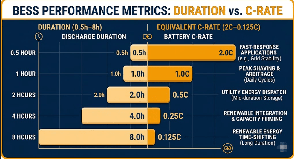
The power-to-energy ratio (P/E ratio) describes how much power (kW) a BESS delivers per unit of stored energy (kWh). A 1-hour system delivers its full energy in one hour — which is exactly a 1C BESS C-rate. As a result, duration and C-rate are mathematical inverses of each other.
Fast-response frequency regulation, EV charging buffer
0.5 hour battery storage, 2C BESS
1-hour BESS
1C
1 kW per kWh
C&I peak shaving, demand charge reduction
1 hour battery storage, 1C BESS
2-hour BESS
0.5C
0.5 kW per kWh
C&I energy arbitrage, solar self-consumption
2 hour battery storage, 2 hour BESS
4-hour BESS
0.25C
0.25 kW per kWh
Grid energy arbitrage, utility time-shifting
4 hour battery energy storage, 4 hour BESS
8-hour BESS
0.125C
0.125 kW per kWh
Long-duration storage, island grid, overnight off-grid supply
8 hour BESS, long duration energy storage
10–12-hour BESS
0.1C
0.1 kW per kWh
Seasonal shifting, remote area power, hydrogen hybrid
long duration battery storage, 10 hour BESS
This table is directly useful for RFP and tender documents. For example, when a grid operator specifies a 4-hour BESS at 100 MW, they are asking for 400 MWh of storage at 0.25C BESS C-rate. Similarly, when a C&I site asks for a 2-hour peak shaving BESS at 500 kW, they need 1 MWh at 0.5C.
📌
When comparing BESS quotations, confirm both the energy (MWh) AND the power (MW or kW). The duration — which is the inverse of BESS C-rate — is the figure that ties them together. Example: ‘500 kWh BESS’ without a stated duration is an incomplete specification. 500 kWh at 1C = 500 kW for 1 hour. The same 500 kWh at 0.5C = 250 kW for 2 hours. Same energy, very different power — and a very different price.
8. PCS Rating and BESS C-Rate: Why the Inverter Can Limit Your System Output
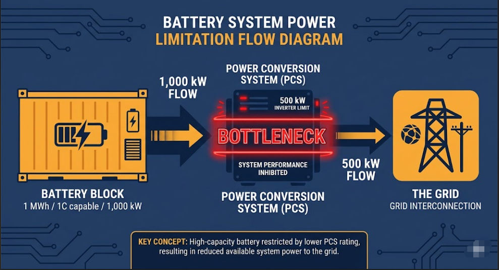
One of the most common and costly mistakes in BESS procurement is assuming that the battery’s C-rate alone determines maximum power output. In practice, this is not the case. The Power Conversion System (PCS) is the inverter or bidirectional converter that connects the battery to the AC grid. It also sets a hard ceiling on power. That ceiling can be significantly lower than the battery’s C-rate capability.
⚠️
Classic BESS C-rate bottleneck example: Battery capacity: 1 MWh LFP Battery C-rate: 1C → capable of 1,000 kW (1 MW) PCS rating: 500 kW Actual system output: 500 kW (limited by PCS, not battery BESS C-rate) Effective C-rate: 0.5C (not 1C)
The battery can run at 1C BESS C-rate. The system cannot. The PCS is the bottleneck.
This situation arises when a developer uses an undersized inverter to reduce upfront cost, or when a site’s grid connection capacity limits the inverter size. In both cases, the battery is paying the price premium for a 1C BESS C-rate it cannot exercise in real operation. Additionally, whether you deploy grid-forming vs grid-following BESS inverters will dictate how the PCS handles these localized capacity constraints and dynamic grid response demands.
PCS Sizing Rules Matched to BESS C-Rate and Application
Application
Recommended Duration
BESS C-Rate
Required PCS Rating
PCS Sizing Rule
Solar self-consumption
2–4 hours
0.25C–0.5C
25–50% of battery kWh as kW
PCS ≥ Battery kWh × C-rate
C&I peak shaving
1–2 hours
0.5C–1C
50–100% of battery kWh as kW
PCS must match peak shaving kW target
Demand charge reduction
30–60 min
1C–1.5C
100–150% of battery kWh as kW
PCS sized to full 1C discharge power
Grid frequency regulation
15–30 min
2C–3C
200–300% of battery kWh as kW
PCS and protection relays rated for peak current
EV fast charging buffer
15–30 min
2C–5C
200–500% of battery kWh as kW
Both battery AND PCS must support full BESS C-rate
The correct approach is to size the PCS first, matching it to the application’s power requirement. Then, size the battery to deliver that power for the required duration. Therefore, always start from the load, not from the battery specification.
Step 1 — Define peak power (kW): what is the maximum power the system must deliver? This sets the PCS rating.
Step 2 — Define duration (hours): how long must the system sustain that power? Combined with Step 1, this gives the energy requirement in kWh.
Step 3 — Confirm BESS C-rate: divide peak power (kW) by total energy (kWh) to get the C-rate. Confirm the battery chemistry supports it.
Step 4 — Verify PCS–battery match: the PCS kW rating must equal or exceed Battery (kWh) × Operating BESS C-rate. Navigating these technical boundaries is a core reason why establishing strong EPC + battery integrator partnerships in C&I energy early in the design phase prevents costly hardware mismatches.
📌
PCS sizing shortcut for BESS C-rate verification: Required PCS rating (kW) = Battery capacity (kWh) × Operating BESS C-rate For a 500 kWh battery at 1C BESS C-rate: PCS ≥ 500 kW For a 500 kWh battery at 2C BESS C-rate: PCS ≥ 1,000 kW For a 500 kWh battery at 0.5C BESS C-rate: PCS ≥ 250 kW
If the PCS is undersized, the effective BESS C-rate is: PCS (kW) ÷ Battery (kWh)
9. Temperature and BESS C-Rate: How Cold Weather Derate Your System
Laboratory BESS C-rate specifications are measured at 25°C. Real-world BESS projects operate in temperatures ranging from -30°C in Nordic and Canadian sites to +45°C in Middle Eastern and Australian installations. Temperature directly affects both the charge C-rate and discharge C-rate that the BMS will permit — and the impact can be dramatic.
How Low Temperature Reduces Charge C-Rate in BESS
Cold temperatures reduce the ionic conductivity of the electrolyte and slow lithium diffusion within the graphite anode. As a result, lithium ions cannot intercalate into the anode fast enough to accommodate a standard charge rate. The excess lithium then plates onto the anode surface instead. This is the same lithium plating risk described in Section 2. However, it is now triggered at much lower charging currents. Modern BMS platforms address this through temperature-dependent charge derating, automatically reducing the charge C-rate as cell temperature falls.
Cell Temperature
Max Charge BESS C-Rate (LFP)
Charge Time Impact
Lithium Plating Risk
BMS Action
Above 25°C
0.5C–1C (full rated)
Standard (2–1 hour)
Low
Full charge current permitted
15°C–25°C
0.3C–0.5C
+20–40% longer
Low–moderate
Mild current reduction
5°C–15°C
0.2C–0.3C
+50–100% longer
Moderate
Significant derating applied
0°C–5°C
0.1C–0.2C
5–10 hours
High
Strong derating; pre-heat recommended
-10°C–0°C
0.05C or disabled
Charging impractical
Very high
BMS may disable charging entirely
Below -10°C
Charging disabled
Not permitted
Severe
Cell heating required before charge
How Temperature Affects BESS Discharge C-Rate
Discharge is less temperature-sensitive than charging because the electrochemical reactions are thermodynamically favoured during discharge. However, cold temperatures do increase internal cell resistance. Consequently, available power decreases and effective capacity falls. For example, a 100 Ah LFP cell rated at 1C discharge and 25°C may only safely sustain 0.7C at 0°C. Beyond that point, terminal voltage drops below the BMS cutoff threshold.
Cell Temperature
Discharge BESS C-Rate Available
Capacity Available (%)
Notes
Above 25°C
Full rated (0.5C–2C)
100%
Full performance. Monitor for overheating at 2C+.
10°C–25°C
Full rated
95–100%
Negligible impact for most commercial BESS.
0°C–10°C
~80% of rated
85–95%
Mild derating. Pre-heat recommended for 2C BESS systems.
-10°C–0°C
~60% of rated
70–85%
Noticeable power and capacity reduction.
Below -20°C
~40% of rated
50–70%
Significant derating. Active heating system essential.
Cold-Weather BESS Design: Four Strategies to Protect C-Rate Performance
Insulated enclosures: containerised BESS in cold climates should use insulated steel enclosures with low-wattage heating elements to maintain cell temperature above 5°C during idle periods.
Battery heating mats: direct cell-level heating pads activate when temperature falls below 5–10°C. The BMS controls this automatically. As a result, the system can recharge at its rated BESS C-rate even in sub-zero ambient conditions.
Thermal buffer in C-rate spec: for projects in cold climates, specify the BESS C-rate at 10°C rather than 25°C. This gives a realistic worst-case recharge window. It also prevents dispatch planning errors.
Liquid thermal management: Liquid-cooled systems with a heat pump can both cool cells in summer and heat them in winter. For sites with a wide temperature range, this is the most capable engineering solution.
💡
Cold-climate BESS C-rate project rule: Always request the manufacturer’s charge derating curve from -20°C to +40°C. Size the recharge window based on the minimum expected cell temperature, not the standard 25°C BESS C-rate specification.
A system with a 2-hour recharge at 25°C may need 5+ hours at 5°C. If the site has two peak events per day, this gap can cause missed dispatch.
Deploying these climate control and thermal safety measures ensures your system remains compliant with international risk management protocols. For a complete breakdown of these compliance requirements, check our guide to the IEC 62933-5 safety standards for ESS frameworks.
10. BESS C-Rate and Battery Warranty: What Manufacturers Actually Guarantee
Battery warranties are frequently misread by buyers. Most manufacturers do not simply warrant a number of years or a number of cycles in isolation. Instead, they warrant a specific combination of cycles, throughput, depth of discharge, operating temperature — and BESS C-rate. Operate outside the warranted C-rate and the warranty may be void, even if every other parameter is within limits.
How BESS C-Rate Appears in the Three Main Warranty Structures
Cycle-based warranty: warrants a number of full charge/discharge cycles (e.g. 4,000 cycles to 80% SoH). The warranted cycle count is stated at a specific BESS C-rate and depth of discharge (DoD). For example: ‘4,000 cycles at 1C / 80% DoD / 25°C’. Operating at 2C BESS C-rate and 80% DoD may reduce the warranted cycle count to 2,500.
Throughput-based warranty: warrants a total energy throughput in MWh (e.g. 3,000 MWh per MWh of installed capacity). This approach is nominally BESS C-rate-agnostic, but manufacturers typically include a maximum continuous C-rate clause that, if exceeded, voids the throughput warranty.
Calendar-based warranty: warrants a minimum SoH at a future date (e.g. 70% capacity retention after 10 years). Calendar warranties almost always include an operating envelope — BESS C-rate, temperature, DoD — that defines the conditions under which the warranty applies.
Warranty Type
Typical BESS C-Rate Condition
What Changes If C-Rate Limit Is Exceeded
What to Ask the Supplier
Cycle-based
1C charge / 1C or 2C discharge at 25°C, 80% DoD
Warranted cycle count reduces; some manufacturers publish a BESS C-rate adjustment table
Request cycle-life curve at your operating C-rate and DoD
Throughput-based
Max continuous BESS C-rate clause (e.g. 1C or 2C)
Throughput warranty voided if max C-rate exceeded
Confirm the maximum C-rate clause and whether burst C-rate is treated differently
Calendar-based
Operating envelope includes BESS C-rate, temp, DoD
Warranty void if operating envelope breached
Request the full BESS C-rate operating envelope in the warranty document — not just the summary term sheet
⚠️
Real BESS C-rate warranty example (illustrative):
Supplier warranty states: ‘6,000 cycles to 80% capacity retention at 0.5C charge / 0.5C discharge / 80% DoD / 25°C’
Your project operates at: 0.5C charge / 2C discharge / 80% DoD / 25°C
Warranted cycles at 2C BESS C-rate may be only 3,000–4,000 — half the headline figure. Consequently, always request the C-rate adjustment table before signing.
BESS C-Rate Warranty Checklist: Five Questions to Ask
Request the cycle-life warranty condition in full — BESS C-rate, DoD, temperature, and SoH end-point.
Ask for a cycle-life vs BESS C-rate adjustment table: how does the warranted cycle count change at your operating rate?
Confirm whether burst BESS C-rate events (e.g. 2C for 30 seconds) are counted differently from continuous C-rate.
Verify that the PCS-enforced maximum C-rate matches the warranty’s maximum BESS C-rate clause — any gap is a warranty risk. Ensure these limits map structurally to the battery cell’s factory compliance standards, as outlined in our overview of IEC certifications for BESS, which dictate the thermal and current boundaries manufacturers are legally allowed to warrant.
For throughput warranties, calculate total expected throughput over the project life and confirm it falls within the warranted limit at your operating C-rate.
Tracking these complex lifetime metrics is becoming highly standardized across the industry. To see how manufacturers are beginning to openly disclose this operational data, see our guide on how the battery passport drives transparency in the energy transition by providing immutable health and C-rate logs.
11. Real Utility-Scale BESS C-Rate Examples: Three Grid Project Profiles
The BESS C-rate concepts in this guide apply across all system scales — from a 50 kWh rooftop unit to a 400 MWh grid project. Reflecting utility deployment patterns tracks in the IEA battery storage report, the three utility-scale examples below show how BESS C-rate, duration, PCS rating, and application interconnect in real project structures.
Example 1 — 100 MW / 400 MWh Grid BESS at 0.25C C-Rate: 4-Hour Energy Arbitrage
Operation: Charges overnight at 0.125C–0.25C BESS C-rate (off-peak wholesale tariff) Discharges 08:00–12:00 at 0.25C (morning peak tariff window) Cycle target: 1 full cycle per day × 365 days × 20-year project life
Why 0.25C BESS C-rate? 4-hour discharge maximises revenue capture across the full morning peak. Lower BESS C-rate reduces cell degradation and minimises thermal management cost. At this scale, 0.25C is the dominant grid arbitrage BESS specification globally.
Example 2 — 50 MW / 100 MWh Frequency Regulation BESS at 0.5C C-Rate
Operation: Participates in Frequency Containment Reserve (FCR) or equivalent market. Injects or absorbs up to 50 MW in response to frequency deviations. Actual average C-rate in operation: ~0.1C–0.2C (short bursts, not full cycles). Nominally sized at 0.5C to maintain full power availability throughout the day.
Why 0.5C? The 2-hour energy buffer ensures the system can sustain a prolonged frequency event without exhausting its state of charge. The PCS is sized for 50 MW regardless of how often it is called to respond.
Example 3 — 20 MW / 20 MWh Fast-Response BESS at 1C C-Rate: 1-Hour Duration
Operation: Paired with a large solar farm for curtailment avoidance and grid services. Discharges at up to 1C during grid frequency events or export constraint windows. An automated energy management system (EMS) for BESS orchestrates this dispatch logic, safely recharging the battery at 0.5C from solar generation within a 2-hour window.
Why 1C? 1-hour BESS is the standard grid services configuration: full power for 60 minutes covers most frequency regulation and peak shaving events. 1C is LFP’s commercial sweet spot — maximum performance, competitive price.
Project
Capacity
Power
Duration
C-Rate
Chemistry
Primary Application
Grid arbitrage BESS
400 MWh
100 MW
4 hours
0.25C
LFP prismatic
Wholesale energy arbitrage, time-shifting
Frequency regulation BESS
100 MWh
50 MW
2 hours
0.5C
LFP prismatic
FCR / FFR grid ancillary services
Fast-response solar BESS
20 MWh
20 MW
1 hour
1C
LFP prismatic
Grid services, curtailment avoidance
12. Battery Chemistry Comparison: C-Rate, Charge, Discharge and Emerging Options
The chemistry table in Section 6 covered the main commercial options. This expanded version adds sodium-ion — an emerging chemistry entering the BESS market — and separates typical charge and discharge C-rates for direct comparison.
Chemistry
Typical Charge C-Rate
Typical Discharge C-Rate
Cycle Life
Energy Density
Cell Cost ($/kWh)
BESS Suitability
Status
LFP (LiFePO4)
0.3C–1C
0.5C–2C
3,000–6,000+
Low–medium
$80–$120
Excellent — commercial standard for all BESS
Mature, dominant
NMC (LiNiMnCoO2)
0.5C–1.5C
1C–3C
1,000–2,000
High
$100–$150
Good — high-power BESS, EV charging buffers
Mature
NCA (LiNiCoAlO2)
0.5C–1C
1C–3C
500–1,500
Very high
$110–$160
Moderate — mainly EV; cost and safety limit BESS use
Mature
LTO (Li4Ti5O12)
5C–10C
5C–10C+
10,000–20,000
Very low
$400–$600
Niche — ultra-fast charging, rail; too costly for BESS
Niche, high cost
High-Power LFP (prismatic)
1C–2C
2C–5C
2,000–4,000
Medium
$100–$140
Good — demand response, fast-response grid services
Growing
Sodium-Ion (Na-ion)
0.5C–2C
1C–4C
2,000–4,000
Low–medium
$60–$90*
Promising — emerging competitor to LFP in grid storage
Emerging (2024–)
📌
Sodium-Ion (Na-ion) — what to know for BESS procurement:
Sodium-ion batteries use sodium instead of lithium as the charge carrier. Key advantages: no cobalt, no lithium, lower raw material cost, better low-temperature performance. Current limitations: lower energy density than LFP (~20–30% less); limited commercial track record.
CATL and BYD have both announced sodium-ion cells for stationary storage. Typical charge C-rate: 0.5C–2C. Typical discharge: 1C–4C. Low-temperature performance is notably better than LFP — may suit cold-climate projects.
* Current Na-ion cell cost structures reflect ongoing 2026 early commercial production volumes. These baseline figures are projected to compress further as gigafactory manufacturing scales and supply chains mature.
13. BESS C-Rate Decision Matrix: Matching Application to Specification
Use this matrix as a starting point for any BESS specification. Find your primary application, read across to the recommended C-rate, chemistry, cooling type, and indicative installed cost range.
Application
Recommended C-Rate
Duration
Chemistry
Cooling
PCS/kWh Ratio
Indicative Installed Cost
Solar self-consumption
0.25C–0.5C
2–4 hours
Standard LFP
Passive / fan
0.25–0.5 kW/kWh
$180–$260/kWh
Energy arbitrage (off-peak)
0.5C
2 hours
Standard LFP
Fan / HVAC
0.5 kW/kWh
$220–$280/kWh
Peak shaving (C&I)
1C
1 hour
LFP prismatic
HVAC
1 kW/kWh
$250–$320/kWh
Demand charge reduction
1C–1.5C
40–60 min
LFP prismatic
HVAC
1–1.5 kW/kWh
$270–$350/kWh
Frequency regulation
1C–2C
30–60 min
LFP / NMC
HVAC / liquid
1–2 kW/kWh
$300–$450/kWh
Island / off-grid grid
0.125C–0.5C
2–8 hours
Standard LFP
Fan / HVAC
0.125–0.5 kW/kWh
$200–$300/kWh
EV charging buffer
2C–5C
15–30 min
High-power LFP/NMC
Liquid cooling
2–5 kW/kWh
$380–$700/kWh
Ultra-fast EV charging
5C–10C
6–15 min
NMC / LTO
Liquid / immersion
5–10 kW/kWh
$700–$1,500/kWh
14. Five Common C-Rate Specification Mistakes — and How to Avoid Them
While capturing the advantages of a battery energy storage system (BESS) can dramatically improve a project’s ROI, design errors during procurement can quickly erase those gains. These five errors appear repeatedly in BESS engineering and EPC tendering, but each is entirely preventable with the knowledge in this guide.
Mistake 1: Specifying a 2C C-Rate When 0.5C Is Sufficient
This is the most expensive and most common mistake. A developer specifying a 2-hour peak shaving system asks for a ‘2C BESS’ when the application actually requires 0.5C. As a result, the system costs 60–80% more than necessary. It also uses liquid cooling the application never demands, and it is built with high-power cells whose extra capability is never exercised. Therefore, always derive C-rate from duration: if you need 2 hours of discharge, you need 0.5C, not 2C.
Mistake 2: Ignoring Charge C-Rate When Planning Dispatch
A BESS specified for 1C discharge is typically limited to 0.5C charge. Yet dispatch schedules are frequently planned around the discharge rate alone. Consequently, the system cannot recharge in time for a second peak event, because the 2-hour recharge window was never accounted for. To avoid this, always plan dispatch around the slower of charge and discharge C-rates.
Mistake 3: Ignoring Temperature Derating on Charge C-Rate
Cold-climate projects often specify a 0.5C charge rate at 25°C. However, the same system may only charge at 0.2C at 5°C, tripling the recharge time. This affects both daily dispatch planning and revenue model accuracy. For this reason, always request the charge derating curve for the minimum expected ambient temperature at the project site.
Mistake 4: Comparing BESS C-Rate Quotations on $/kWh Alone
A 500 kWh system at $220/kWh and a 500 kWh system at $320/kWh look like a simple $50,000 saving in favour of the cheaper option. But the $220/kWh system may be rated at 0.5C, while the $320/kWh system is rated at 1C. In that case, the cheaper system delivers only 250 kW. The more expensive system, meanwhile, delivers 500 kW. For a peak shaving application requiring 500 kW, the cheaper system simply cannot do the job. Always compare $/kW alongside $/kWh.
Mistake 5: Forgetting PCS Limitations on BESS C-Rate
A 1 MWh battery with a 1C rating is technically capable of 1 MW output. But if the PCS is rated at only 500 kW, the system is effectively a 0.5C system, regardless of the battery’s rating. Therefore, confirm that the PCS kW rating is equal to or greater than the battery capacity (kWh) multiplied by the required operating C-rate. This check takes only 30 seconds. Yet it can save months of project rework.
📌
Quick specification health-check: 1. C-Rate = Duration inverse? Duration 2 hours → 0.5C ✓ 2. PCS ≥ Battery (kWh) × C-Rate? 500 kWh × 1C = 500 kW PCS minimum ✓ 3. Charge C-rate in dispatch plan? 0.5C charge = 2 hr recharge window ✓ 4. Warranty states C-rate condition? Confirm cycle count at operating C-rate ✓ 5. Temperature derating requested? Get charge curve from -10°C to +40°C ✓
15. C-Rate Procurement Checklist: Eight Questions to Ask Every Supplier
Before signing any BESS supply agreement, confirm the following C-rate parameters in writing:
1. Rated continuous C-rate: maximum C-rate the system sustains indefinitely without thermal or SoH risk. Confirm for both charge and discharge independently.
2. Peak C-rate and burst duration: maximum C-rate for short bursts (typically 10–30 seconds). Confirm the burst duration before BMS curtailment activates.
3. Capacity derating curve: how much kWh does the system actually deliver at your operating C-rate — not just at the 1C nameplate condition?
4. Cycle life at operating C-rate: request the cycle-life warranty condition (C-rate, DoD, temperature) and a C-rate adjustment table in writing.
5. Charge derating curve vs temperature: request the charge C-rate curve from the minimum expected site temperature to +40°C.
6. PCS–battery C-rate match: confirm the PCS kW rating equals or exceeds Battery (kWh) × Operating C-rate.
7. Thermal management design C-rate: confirm the cooling system is sized for your intended C-rate, not nominal conditions.
8. Warranty C-rate operating envelope: request the full warranty operating envelope and confirm your project’s C-rate falls within the warranted range.
16. Frequently Asked Questions: BESS C-Rate
What is a good C-rate for a BESS?
For most commercial and industrial BESS applications, 0.5C to 1C is the optimal range. A 0.5C system (2-hour duration) suits solar self-consumption and energy arbitrage. A 1C system (1-hour duration) is the standard for peak shaving and demand charge reduction. Higher C-rates are only justified for grid frequency regulation (1C–2C) or EV fast charging buffers (2C–5C).
Is a higher C-rate always better?
No. A higher C-rate means higher peak power output — but it also means higher system cost, faster cell degradation, and greater thermal management requirements. Specifying a higher C-rate than your application requires wastes capital and shortens battery life. Match the C-rate to the application, not to the maximum available specification.
What C-rate is used for peak shaving?
Peak shaving typically uses a 1C discharge rate, which delivers full rated power for one hour. Sites with sharp, short demand spikes may specify 1.5C for a 40-minute discharge window. Sites with longer, flatter demand peaks may use 0.5C for a 2-hour window. The correct C-rate depends on the duration and shape of the demand event, not a single standard answer.
What C-rate is used for solar energy storage?
Solar self-consumption BESS typically operates at 0.25C to 0.5C — discharging over 2 to 4 hours through the evening peak. This slow discharge maximises the energy extracted per cycle, minimises heat generation, and extends cycle life. LFP cells at 0.5C can sustain over 6,000 – 8,000 cycles — enough for 16+ years of daily operation at 80% depth of discharge.
How does C-rate affect battery lifespan?
Higher C-rates accelerate three degradation mechanisms. These are electrolyte oxidation from heat (I²R), mechanical stress from rapid lithium intercalation, and SEI layer growth from elevated temperatures. As a result, a battery cycled at 2C will typically reach 80% SoH in only 2,000–3,000 cycles. The same battery at 0.5C, however, may sustain 5,000–6,000 cycles. Overall, operating at or below 1C is the single most effective way to extend LFP battery life.
What Is the Difference Between a 0.5C and 1C BESS C-Rate?
A 0.5C system takes twice as long to discharge as a 1C system. For a 500 kWh battery, 0.5C delivers 250 kW for 2 hours, while 1C delivers 500 kW for 1 hour. Both deliver the same total energy of 500 kWh. However, the 1C system delivers it at twice the power. Consequently, a 1C system costs roughly 20–40% more than a 0.5C system of the same kWh capacity. This premium reflects higher-rated power electronics and more capable thermal management.
Does a higher C-rate increase battery cost?
Yes, and the increase is significant. Every major cost component scales with C-rate. Cell chemistry costs more for higher-power cells. Thermal management shifts from air to liquid cooling above 1.5C. The inverter and PCS need larger transistors and busbars for higher current. The BMS also needs faster sampling and protection. Overall, a 2C system typically costs 50–80% more per kWh than a 0.5C system of identical capacity.
What C-rate is common in utility-scale BESS?
Utility-scale BESS varies widely by application. Grid arbitrage projects, which are typically 4-hour systems, operate at 0.25C. Frequency regulation projects, usually 2-hour systems, operate at 0.5C. Meanwhile, grid services BESS paired with solar farms commonly use 1C. In 2024–2025, the dominant global configuration is 2-hour to 4-hour LFP at 0.25C to 0.5C. This trend is largely driven by the falling cost of large-format LFP prismatic cells.
Conclusion: Getting BESS C-Rate Right From the Start
BESS C-rate is not a secondary datasheet figure. Instead, it is the specification that determines how much power your system delivers, how quickly it recharges, and how long the cells last. Directly, it also determines how much the system costs. Furthermore, it connects to the duration language EPCs use, such as 1-hour or 4-hour systems. It links to the PCS sizing your electrical engineer specifies. It links, too, to the warranty conditions your finance team relies on. Finally, it links to the temperature performance your operations team will encounter on site.
For LFP BESS in commercial and grid-scale applications, the 0.5C to 2C range covers the vast majority of real-world deployments. Before selecting a chemistry, a PCS, or a cooling system, map your application to the correct C-rate tier first. This single step is the highest-value part of the procurement process.
Need help sizing a BESS to the right C-rate for your load profile and grid requirements? Contact SunLith Energy to speak with a storage engineer.
BESS communication protocols are the rules that let every part of a battery storage system share data.
So without them, batteries, inverters, and grid systems cannot work together.
Each device in a BESS speaks a different digital language. But a shared protocol gives them a common way to talk.
For example, the battery uses CAN Bus internally. The inverter, however, often uses Modbus. And the grid uses IEC 61850.
Choosing the right BESS communication protocols matters a lot. A bad choice leads to slow integration, poor performance, and higher costs.
Why BESS Communication Protocols Affect System Safety
Speed is critical in a BESS. A fault signal must reach the controller in milliseconds. So the protocol must be fast enough to carry it in time.
Also, the protocol must be reliable. If a message is lost, the system may not shut down safely. Therefore, engineers choose protocols based on both speed and reliability.
In addition, some protocols are secure by design. Others, however, have no built-in encryption. As a result, security must be added at the network level for older protocols.
BESS communication protocols work across five system layers. Each layer has different speed needs and data types. So understanding these layers helps you pick the right protocol at each level.
Layer
Component
Common Protocols
1 — Cell
Battery cells, modules, BMUs
CAN Bus, SMBus
2 — BMS
Battery Management System
Modbus RTU, CAN Bus, RS-485
3 — PCS
Power Conversion System / Inverter
Modbus TCP, CAN Bus, PROFINET, EtherNet/IP
4 — EMS
Energy Management System
Modbus TCP, OPC UA, MQTT, IEC 60870-5-104
5 — Grid
Utility / SCADA / Cloud
IEC 61850, DNP3, IEEE 2030.5, MQTT, REST
No single protocol covers all five layers. So most BESS projects use three or four protocols together.
As a result, a protocol gateway is almost always part of a real BESS design. We cover this in detail later.
The five layers of BESS communication protocols — from CAN Bus at cell level to IEC 61850 at the grid
1. Modbus — The Most Widely Used BESS Communication Protocol
Modbus is the most common BESS communication protocol in the world. It was developed in 1979, but it is still used in almost every BESS project today.
So why is it so popular? Because it is simple, cheap, and works with every BESS hardware vendor.
How Modbus Works as a BESS Communication Protocol
Modbus uses a master-slave model. One master — usually the EMS — sends a request to a slave device such as the BMS. The slave then replies with its data.
There are two forms. First, Modbus RTU sends binary data over an RS-485 serial cable. Then, Modbus TCP sends the same data over a standard Ethernet network. As a result, Modbus TCP works across a local area network or even the internet.
In a BESS, Modbus TCP links the BMS to the EMS and SCADA systems. So it is how most BESS assets respond to grid operator commands.
Why Modbus Has Limits as a BESS Communication Protocol
Modbus is easy to use, but it does have gaps. For example, it has no built-in security. Also, it uses polling, which adds latency.
However, these gaps are manageable. Engineers add security at the network level. And for most BESS use cases, the polling delay is acceptable.
But Modbus should not be the only protocol on an external BESS interface. For that reason, most projects combine it with a secure protocol like OPC UA or IEEE 2030.5.
STRENGTHS ✓ Works with every BESS hardware vendor ✓ Simple to set up and easy to debug ✓ No licence cost ✓ Runs over RS-485 serial and Ethernet TCP/IP
LIMITATIONS ✗ No built-in encryption or authentication ✗ Polling model adds latency ✗ Limited data model vs IEC 61850 ✗ Not suitable alone for utility-facing use
Used for: BMS ↔ EMS, BMS ↔ PCS, SCADA, field instruments
Modbus RTU over RS-485 (BMS to Inverter) and Modbus TCP over Ethernet (Inverter to EMS to SCADA)
2. CAN Bus — The Internal BESS Communication Protocol
CAN Bus is the backbone of every battery rack. It was built for cars, but it also works perfectly inside BESS enclosures.
In fact, it is now found in products from BYD, CATL, Huawei, Sungrow, and Pylontech. So it has become the standard for internal BESS communication.
Why CAN Bus Suits BESS Internal Communication
CAN Bus uses a two-wire pair — CAN-H and CAN-L. This design blocks interference from the high-current switching inside a battery cabinet.
Also, CAN Bus is a multi-master system. So every node — modules, BMUs, and the BMS controller — can send data at any time. As a result, the system gets real-time updates without waiting to be polled.
Furthermore, China’s national grid standards require CAN Bus as the BMS-to-inverter link in all utility-scale BESS projects. So it is not just popular — it is often mandatory.
CAN Bus Limits in a BESS System
CAN Bus is fast, but its range is short. At 1 Mbit/s, cables can be no longer than 40 metres. Therefore, it cannot be used beyond the battery enclosure.
However, a gateway solves this. The gateway reads CAN Bus data and then sends it upstream as Modbus TCP, MQTT, or another BESS communication protocol.
STRENGTHS ✓ Resists EMI via differential CAN-H / CAN-L signalling ✓ Error detection and arbitration built in ✓ Real-time, event-driven — no polling needed ✓ Used by all major BESS OEMs
LIMITATIONS ✗ Short cable range — max 40 m at 1 Mbit/s ✗ Cannot reach the utility or cloud layer ✗ Vendor register maps differ between brands ✗ Needs a gateway for EMS or cloud integration
CAN Bus inside a BESS — modules report to BMUs, BMUs report to the BMS master, the BMS master connects to the PCS
3. IEC 61850 — The Grid-Level BESS Communication Protocol
IEC 61850 is the international standard for substation automation. It is also the leading BESS communication protocol for utility grid connections, especially in Europe and Asia-Pacific.
Unlike Modbus, it defines a full information model — not just a transport layer. So any IEC 61850 device can talk to any other, no matter the brand.
What Makes IEC 61850 Different
IEC 61850 uses logical nodes and data objects to describe every piece of equipment. As a result, there is no need for custom register mapping between vendors.
Also, IEC 61850-7-420 extends the standard to cover Distributed Energy Resources, including BESS. However, this DER extension is still developing. So some projects use custom mappings alongside the standard.
GOOSE Messaging — Speed That Other BESS Communication Protocols Cannot Match
GOOSE stands for Generic Object-Oriented Substation Event. It delivers event signals in under one millisecond. Therefore, it is used for protection — where a delayed signal could mean a fault goes uncleared.
MMS, in contrast, handles scheduled data exchange between the EMS and the utility. Together, GOOSE and MMS give IEC 61850 a range that no other BESS communication protocol can match alone.
When to Specify IEC 61850 for Your BESS
Use IEC 61850 for any utility-scale BESS in Europe, the UK, or Asia-Pacific. Many regulators now require it for all new grid-connected storage assets.
Furthermore, specifying it early avoids costly retrofits. So include it in the EMS and gateway specification from day one.
STRENGTHS ✓ True multi-vendor interoperability — no register mapping ✓ GOOSE delivers sub-millisecond protection events ✓ Rich, self-describing data model ✓ Mandated by EU, UK, and APAC utility operators
LIMITATIONS ✗ Higher engineering cost than Modbus ✗ DER model (7-420) still maturing ✗ Not all BESS OEMs support it natively ✗ Needs SCL configuration expertise
Used for: EMS ↔ Utility SCADA, substation automation, protection, VPP
IEC 61850 links the BESS EMS to the utility control centre via GOOSE events and MMS data exchange
4. DNP3 — The North American Utility BESS Communication Protocol
DNP3 is the standard BESS communication protocol for utility SCADA in North America. It is formally specified under IEEE Std 1815 and has been in use since 1993.
So if your BESS connects to a North American utility, you will almost certainly need DNP3.
Why DNP3 Works Well for Remote BESS Sites
DNP3 was built for tough conditions. It works over serial radio links, low-bandwidth WAN, and cellular networks. As a result, it suits remote BESS sites where network quality is poor.
Also, DNP3 supports unsolicited reporting. This means the BESS sends data only when something changes. So it uses far less bandwidth than a polling protocol like Modbus.
Adding Security to DNP3 in BESS Projects
The base DNP3 standard has no native security. However, Secure Authentication v5 (SAv5) adds a challenge-response layer. This significantly improves protection on any BESS grid link.
NERC CIP standards require strong authentication on all utility-connected BESS assets in North America. Therefore, SAv5 is now a standard requirement in most DNP3 BESS specifications.
STRENGTHS ✓ Reliable over poor network links — serial, radio, cellular ✓ Unsolicited reporting cuts bandwidth ✓ Leading protocol for North American utility SCADA ✓ Timestamped events support accurate fault logging
LIMITATIONS ✗ Less rich data model than IEC 61850 ✗ Security needs SAv5 as a separate add-on ✗ Rarely used outside North America ✗ Not suited to cloud or IoT use
Used for: EMS ↔ Utility SCADA, remote BESS, North American grid connections
DNP3 links the BESS EMS to the utility SCADA master over a WAN with unsolicited reporting and SAv5 authentication
5. OPC UA — The Secure Cloud BESS Communication Protocol
OPC UA connects BESS systems to cloud platforms and enterprise software. It is specified under IEC 62541 and is widely used in industrial IoT deployments.
Unlike older protocols, it is secure by design. So it is a strong choice for any external-facing BESS interface.
How OPC UA Improves on Legacy BESS Communication Protocols
Legacy OPC was Windows-only and had no encryption. OPC UA, however, works on any platform — Linux, Windows, or embedded controllers.
Also, OPC UA uses TLS encryption by default. So every connection is secure without any extra setup. In addition, it uses a rich object model that represents a full BESS asset in a structured, self-describing format.
As a result, cloud analytics platforms can ingest BESS data without any custom engineering. So it saves time and reduces integration risk.
Combining OPC UA and IEC 61850 in Large BESS Projects
The best approach for utility-scale BESS is to use both. IEC 61850 handles real-time grid communication. OPC UA, in contrast, carries asset data to cloud analytics and digital twin platforms.
Furthermore, AWS, Azure, and Google Cloud all support OPC UA PubSub natively. Therefore, OPC UA provides a direct, secure path from the BESS site to cloud tools.
STRENGTHS ✓ TLS encryption built in — no add-on needed ✓ Works on any platform — Linux, Windows, embedded ✓ Rich object model for complex BESS data ✓ Native support in AWS, Azure, and Google Cloud
LIMITATIONS ✗ Heavier than MQTT for simple data streams ✗ Too complex for small C&I BESS projects ✗ Higher engineering cost than Modbus ✗ Slower to implement than simpler alternatives
Used for: EMS ↔ Cloud, asset management, digital twins, predictive maintenance
OPC UA connects the BESS EMS to cloud analytics and enterprise platforms via a TLS-encrypted channel
6. MQTT — The Cloud Telemetry BESS Communication Protocol
MQTT is a lightweight protocol for cloud telemetry. It is now the most popular BESS communication protocol for real-time monitoring and remote dashboards.
So if you want to stream battery data to the cloud, MQTT is the best place to start.
How MQTT Works in a BESS
MQTT uses a broker between publishers and subscribers. The BMS gateway publishes data — such as state of charge, temperature, and fault codes — to the broker.
Then cloud dashboards subscribe and receive that data in near real time. Also, the publisher-subscriber model means you can add new cloud apps without touching any hardware.
Furthermore, IEC 61850 data models can be mapped directly to MQTT topics. So a single gateway can serve both the grid and the cloud at the same time.
MQTT and the EU Battery Passport
The EU is introducing Battery Passport rules for storage assets. MQTT is well-suited to Battery Passport data exports because of its lightweight, streaming design.
As a result, MQTT is increasingly specified alongside IEC 61850 in European BESS projects. So it is becoming a standard part of the cloud layer in most modern designs.
STRENGTHS ✓ Very lightweight — low bandwidth and CPU use ✓ Best choice for high-frequency streaming data ✓ Native support in AWS, Azure, and Google Cloud ✓ Publisher-subscriber model is flexible and scalable
LIMITATIONS ✗ No built-in BESS data model — custom topics needed ✗ Not suitable for direct control commands ✗ QoS levels must be configured carefully ✗ TLS must be switched on manually
MQTT broker connects the BESS BMS gateway to cloud dashboards, analytics, and Battery Passport services
7. PROFINET and EtherNet/IP — Real-Time BESS Communication Protocols
PROFINET and EtherNet/IP are Industrial Ethernet protocols. They are used inside containerised BESS units where Modbus TCP is not fast or precise enough.
So if your BESS has a PLC controlling HVAC, fire suppression, and the inverter, these protocols are likely the right choice.
When to Use These Real-Time BESS Communication Protocols
Modbus TCP is fine for most BMS-to-EMS links. But it cannot guarantee the timing needed for fast power electronics.
PROFINET and EtherNet/IP, in contrast, are deterministic. They deliver messages within a fixed time window. As a result, charge and discharge commands arrive at exactly the right moment.
Also, both support IEEE 1588 Precision Time Protocol. This keeps all BESS components synchronised to within microseconds. Therefore, they are ideal for frequency regulation services that need sub-second response.
PROFINET vs EtherNet/IP — Which One Should You Choose?
PROFINET is the standard choice in Europe and Asia. It works best with Siemens TIA Portal and Siemens PLCs.
EtherNet/IP, however, is more common in North America. It is the native protocol for Rockwell Automation hardware. So the right choice usually depends on which PLC the project already uses.
STRENGTHS ✓ Deterministic real-time communication ✓ Gigabit Ethernet capable — high throughput ✓ IEEE 1588 PTP for microsecond synchronisation ✓ Tight integration with Siemens (PROFINET) and Rockwell (EtherNet/IP)
LIMITATIONS ✗ Vendor lock-in — PROFINET and EtherNet/IP are not compatible ✗ Higher infrastructure cost than Modbus TCP✗ Not used for utility or cloud communication ✗ Needs managed switches with QoS and VLAN support
Used for: BMS ↔ PCS sync, containerised BESS with PLC, auxiliary system automation
Real-time industrial Ethernet connecting PLC, BMS, PCS, HVAC, and fire suppression inside a containerised BESS
8. IEEE 2030.5 — The Compliance BESS Communication Protocol
IEEE 2030.5 is a secure, RESTful protocol for connecting BESS to utility systems. It is mandatory under California Rule 21 for all grid-connected BESS in California.
So if your project is in California — or a state adopting similar rules — you will need this protocol.
Why IEEE 2030.5 Is the Most Secure BESS Communication Protocol
Unlike Modbus or DNP3, IEEE 2030.5 requires TLS 1.2 on every connection. There is no optional configuration — it is always on.
Also, it uses standard HTTPS calls. So it fits naturally into modern IT networks. As a result, integration with utility head-end systems is simpler than with legacy serial protocols.
Using IEEE 2030.5 Without Replacing Your BESS Hardware
Most existing BESS hardware does not natively support IEEE 2030.5. However, a protocol gateway solves this easily.
The gateway translates from SunSpec Modbus or DNP3 on the device side to IEEE 2030.5 on the utility side. So operators can achieve full Rule 21 compliance without any new field hardware.
In addition, more US states and international regulators are expected to adopt similar DER rules by 2030. Therefore, specifying IEEE 2030.5 gateway support today future-proofs the asset.
STRENGTHS ✓ TLS 1.2 mandatory — security built in ✓ RESTful HTTPS fits modern networks ✓ California Rule 21 and CSIP compliant ✓ Works via gateway — no hardware replacement needed
LIMITATIONS ✗ Primarily a North American standard ✗ REST polling too slow for fast control loops ✗ Needs specialist Rule 21 / CSIP knowledge ✗ Smaller vendor ecosystem than DNP3 or Modbus
Used for: BESS DER interconnection, California Rule 21, utility scheduling and monitoring
IEEE 2030.5 connects the BESS gateway to the utility head-end via HTTPS with TLS 1.2 — required by California Rule 21
All BESS Communication Protocols Compared
The table below compares all eight BESS communication protocols side by side. Use it to quickly find the right protocol for each layer of your system.
Protocol
Layer
Real-Time
Security
Utility
Cloud/IoT
Modbus RTU/TCP
BMS ↔ EMS/PCS
Polling
None
Via SCADA
No
CAN Bus
Cell ↔ BMS
Yes
None
No
No
IEC 61850
EMS ↔ Grid
GOOSE <1ms
Opt. TLS
Yes
Via mapping
DNP3
EMS ↔ Utility
Low latency
SAv5
N. America
No
OPC UA
EMS ↔ Cloud
Near RT
TLS
Emerging
Yes
MQTT
EMS ↔ Cloud
Streaming
Opt. TLS
No
Yes
IEEE 2030.5
EMS ↔ Utility
REST poll
TLS mandatory
Yes
Possible
PROFINET/EtherNet-IP
BMS ↔ PCS
Deterministic
Network
No
No
Why Every BESS Needs a Protocol Gateway
No BESS project uses just one communication protocol. CAN Bus batteries connect to Modbus inverters. Modbus inverters connect to IEC 61850 substations. DNP3 talks to SCADA. MQTT streams data to the cloud.
So a protocol gateway is what holds the whole system together. It translates data between protocols in real time.
What a BESS Protocol Gateway Does
A good gateway supports IEC 61850, DNP3, Modbus, OPC UA, and MQTT — all at the same time. As a result, the BESS can serve both the utility and the cloud from a single device.
Also, a gateway future-proofs the asset. So when utility requirements change, you update the gateway — not the hardware. This saves a lot of time and cost later in the project.
The Golden Rule for BESS Communication Protocol Design
Design the gateway first Specify your protocol gateway before you procure any hardware. This one decision shapes every grid service, every cloud integration, and every future revenue stream. Retrofitting protocol support after commissioning is expensive and often technically very difficult.
A BESS protocol gateway translates CAN Bus, Modbus, IEC 61850, DNP3, and MQTT simultaneously at the centre of the communication stack
How to Pick the Right BESS Communication Protocols
For Commercial and Industrial BESS Projects
Most C&I projects use CAN Bus inside the battery rack. Then they use Modbus RTU between the BMS and inverter. After that, Modbus TCP connects the inverter to the EMS. Finally, MQTT pushes telemetry to the cloud.
This stack is cost-effective and easy to commission. Also, it is supported by every major BESS hardware vendor. So it is the best starting point for most behind-the-meter projects.
Utility-scale projects need IEC 61850 in Europe and APAC. In North America, however, DNP3 is the SCADA standard. In California, IEEE 2030.5 is also required.
As a result, the EMS must speak all three. A multi-protocol gateway or a native multi-protocol EMS platform makes this possible.
Cybersecurity Rules for BESS Communication Protocols
Modbus and CAN Bus have no built-in security. So they need network-level protection — firewalls, VPNs, and strict network segmentation.
For external interfaces, use a secure protocol by design. For example, OPC UA, IEEE 2030.5, or DNP3 with SAv5 are all good choices.
OPC UA: TLS encryption and X.509 certificates built in
IEEE 2030.5: TLS 1.2 mandatory on every connection
DNP3 SAv5: Challenge-response authentication add-on for existing systems
Modbus / CAN Bus: Protect with firewalls, VPNs, and network segmentation
Also, NERC CIP standards apply to all utility-connected BESS in North America. Therefore, document all security controls for every communication interface.
Key Standards and References for BESS Communication Protocols
The sources below give primary-source detail on each BESS communication protocol. They are recommended for engineers who need full specification documents.
Conclusion — Choosing the Right BESS Communication Protocols
Choosing the right BESS communication protocols is one of the most important design decisions in any energy storage project. Get it right and the system integrates smoothly. Get it wrong and commissioning becomes painful and expensive.
So start with the basics. Use CAN Bus and Modbus for internal communication. Then add IEC 61850 or DNP3 for the utility interface. Finally, layer in OPC UA or MQTT for cloud analytics.
Above all, specify a capable protocol gateway early. It is the device that makes all the other protocols work together. And it keeps every integration option open as requirements change over the asset’s life.
If you are confused about kWh vs kW explained, you are not alone. Many people mix up these terms. However, they measure different things.
In simple terms, kW (kilowatt) measures power. On the other hand, kWh (kilowatt-hour) measures energy over time. Therefore, understanding this difference is critical for solar and battery sizing.
🔍 kWh vs kW Explained: What Is kW (Kilowatt)?
kW measures how fast energy is used or produced. In other words, it is the rate of power.
For example:
A 1 kW heater uses 1 kilowatt of power
A 5 kW solar system produces 5 kilowatts at peak
Therefore, kW tells you instant power, not total energy.
🔋 kWh vs kW Explained: What Is kWh (Kilowatt-Hour)?
kWh measures total energy consumed over time. It combines power and duration.
Formula:
Energy (kWh) = Power (kW) × Time (hours)
Example:
1 kW device running for 5 hours = 5 kWh
2 kW AC running for 3 hours = 6 kWh
As a result, kWh tells you how much energy you actually use.
⚖️ kWh vs kW Explained: Key Difference
Metric
kW
kWh
Meaning
Power
Energy
Measures
Rate
Total usage
Example
5 kW system
20 kWh per day
Use Case
System size
Energy consumption
Therefore, kW is capacity, while kWh is consumption.
☀️ kWh vs kW Explained in Solar Systems
Solar systems use both values. However, they serve different purposes.
kW → Solar system size
kWh → Daily energy generation
For example:
A 5 kW system does not produce 5 kWh per day
It produces energy based on sunlight
👉Solar output depends on sunlight intensity. Therefore, understanding peak sun hours by location is essential for accurate energy calculations.
🔋 kWh vs kW Explained in Battery Storage
Battery systems are measured in kWh. This is because they store energy.
However, batteries also have a kW rating. This shows how fast they can deliver power.
👉 In addition, solar and battery systems must be sized together. You can follow this energy storage calculation guide to design a complete system.
📉 kWh vs kW Explained with Real Example
Let’s break it down:
Solar system size = 6 kW
Peak sun hours = 5
Energy produced:
6 × 5 = 30 kWh per day
However, losses reduce output.
👉 However, actual energy output is lower due to inefficiencies. Learn more about energy storage system losses and their impact on system performance.
🧮 kWh vs kW Explained for Home Electricity Bills
Your electricity bill shows kWh. This is because utilities charge based on total energy used.
For example:
Monthly usage = 900 kWh
Daily usage ≈ 30 kWh
Therefore, kWh determines your cost.
🔢 kWh vs kW Explained for Solar Panel Sizing
To size a solar system, you must convert kWh into kW.
Formula:
System Size (kW) = Daily Energy (kWh) ÷ Peak Sun Hours
⚠️ Common Mistakes in kWh vs kW Explained
Many users misunderstand these terms. As a result, they design incorrect systems.
⚡ Quick Answer: What Is a Battery Management System? A battery management system (BMS) is the electronic brain inside every lithium battery pack. It monitors cell voltage, current, and temperature in real time. It also protects cells from overcharge, over-discharge, short circuit, and thermal runaway. Furthermore, it estimates State of Charge (SOC) and State of Health (SOH). Without a BMS, a lithium battery is both unsafe and short-lived.
Every lithium BESS relies on a battery management system to run safely. This is true for a 10 kWh home install and a 10 MWh grid system alike. In both cases, therefore, the BMS is not optional — it sits between your cells and everything that can destroy them.
Yet the BMS is one of the most overlooked parts of any BESS purchase. Buyers focus on cell chemistry, capacity, and cycle life. Then they treat the battery management system as a given. That is a costly mistake.
A poor BMS, therefore, degrades good cells. A great battery management system, in contrast, extends the life of average cells. It is a lifespan management tool — not just a safety device.
This guide explains how a battery management system works, what it monitors, and how it balances cells. We also cover SOC and SOH calculation and show you how to evaluate a supplier’s BMS before you sign. For context on how the BMS interacts with cell chemistry, first read our LiFePO4 vs NMC battery comparison guide.
1. What Is a Battery Management System?
How a battery management system connects cells, inverter, EMS, and monitoring platform
A battery management system (BMS) is an electronic control unit built into a battery pack. Specifically, its job is to protect cells, measure their state, and report data to the rest of the system.
Think of the BMS as doing three jobs at once. First, it acts as a protection circuit — preventing electrical and thermal damage to the cells. Second, it is a measurement system — tracking voltage, current, temperature, SOC, and SOH. Third, it is a communication hub — sending live data to the inverter, EMS, and monitoring platform.
In a simple 12V residential pack, the BMS is a small PCB inside the module. In a commercial BESS, however, it manages hundreds of cells at once. The scale changes — but the core functions stay the same.
🔋 Why the Battery Management System Determines Lifespan Two identical cell packs with different BMS implementations deliver very different lifespans. Specifically, a BMS that allows cells to hit voltage limits, run hot, or drift out of balance will shorten cell life — regardless of the chemistry’s rated cycle count. The battery management system is, therefore, as important as the cells themselves.
2. Battery Management System Functions: The Seven Core Jobs
A well-designed battery management system performs seven distinct functions. Each one protects the battery in a different way. Together, furthermore, they determine whether your BESS is safe, efficient, and long-lived.
2.1 Cell Voltage Monitoring
The BMS monitors every individual cell voltage — not just overall pack voltage. This matters because cells in a multi-cell pack drift apart over time. Specifically, one weak cell can hit its limit before the others do.
For LiFePO4 cells, the safe range is 2.5V to 3.65V per cell. Going outside this range — even briefly — causes permanent capacity loss. So the BMS must, therefore, detect and respond to violations in milliseconds.
Voltage monitoring also underpins SOC estimation, which we cover in Section 5. Without accurate cell-level data, furthermore, everything else the BMS does becomes unreliable.
2.2 Current Monitoring and Overcurrent Protection
The BMS measures charge and discharge current using a shunt resistor or Hall-effect sensor. Specifically, this data serves four purposes:
Coulomb counting — integrating current over time to estimate SOC
Overcurrent protection — detecting short circuits and excessive discharge rates
C-rate enforcement — ensuring cells never charge or discharge faster than their rated speed
Power limiting — reducing available power as SOC drops or temperature rises
2.3 Temperature Monitoring
Temperature is one of the biggest drivers of battery degradation. Consequently, the BMS places sensors at multiple points — cell surfaces, busbars, and the enclosure. It uses this data to trigger cooling and reduce current.
It also halts charging below 0°C. Charging below freezing causes lithium plating. This is permanent anode damage that cannot be reversed.
For LiFePO4, the safe charging range is 0°C to 45°C. Discharge, however, runs across a wider range of -20°C to 60°C. The BMS enforces both limits automatically.
2.4 Overcharge and Over-Discharge Protection
These are the two most critical BMS protection functions. Overcharging a lithium cell causes irreversible changes in the cathode. Similarly, over-discharging collapses the anode. Both permanently reduce capacity.
The BMS prevents both by triggering a contactor disconnect when any cell breaches its voltage limit. This happens even if the pack’s overall voltage looks normal. One weak cell can hit its limit while others still have headroom. That is why cell-level monitoring is non-negotiable.
2.5 Short Circuit Detection and Response
A short circuit sends a massive current spike through the pack in milliseconds. Without protection, the heat this creates can trigger thermal runaway. As a result, the BMS detects the spike and opens the contactor in microseconds — before damage occurs. Learn more about how these critical failure paths are analyzed and mitigated in our engineering deep-dive on BMS Functional Safety, HARA, and FMEA.
Furthermore, sustained overcurrent protection prevents operation at damaging C-rates. This applies even without a sudden short circuit event.
2.6 Cell Balancing
Cell balancing is one of the most important long-term BMS functions. It keeps all cells at the same State of Charge. Without it, the weakest cell limits the entire pack — even though the others still have energy to give.
We cover passive vs. active balancing in detail in Section 4. The key point, however, is this: balancing quality directly affects how much rated capacity you can use over time. In other words, poor balancing means lost energy.
2.7 Communication and Data Reporting
A modern battery management system communicates with the inverter, EMS, SCADA, and remote monitoring platforms. In particular, the most common protocols include:
CAN bus — standard in high-performance BESS and automotive applications
RS485 / Modbus RTU — common in commercial and industrial storage
MQTT / TCP-IP — used for cloud monitoring and Battery Passport data exports
For a comprehensive look at how these networks function and talk to one another, read our complete guide on BESS Communication Protocols.
The BMS transmits SOC, SOH, cell voltages, temperatures, current, cycle count, and fault codes. Specifically, this data feeds dispatch decisions in the EMS and enables remote health tracking.
3. Battery Management System Architecture Options
BMS architecture scales with system size. Specifically, there are three implementation levels. Each one adds capability and complexity.
BMS Tier
Also Called
Scope
Typical Application
Cell-level BMS
CBMS
Monitors individual cells in one module
Residential storage under 30 kWh
Module BMS
Slave BMS / MBMS
Manages one group of cells in a module
C&I systems, EV battery packs
System / Master BMS
SBMS / Master BMS
Coordinates all modules in the full pack
Utility-scale BESS, multi-rack systems
Single-Level BMS (Residential)
In smaller systems — typically under 100 kWh — a single BMS manages all cells directly. This is a simple, low-cost architecture. Consequently, the BMS PCB sits inside the battery module and handles monitoring, protection, and balancing on its own.
However, as cell count grows, wiring becomes complex and processing load increases. Beyond a certain size, single-level BMS becomes impractical.
Master-Slave BMS (Commercial and Utility Scale)
In larger systems — typically above 100 kWh — a master-slave design is used. Each battery module has its own Slave BMS. It handles local cell monitoring and balancing. All Slave units then report to a central Master BMS, which coordinates the full system.
The Master BMS aggregates data from all modules and manages system-level protection. Furthermore, it communicates with the inverter and EMS. As a result, this architecture scales well to multi-megawatt-hour systems.
⚠️ Key Evaluation Point: Master-Slave Independence In a quality master-slave battery management system, each slave module should protect its own cells independently — even if communication with the master is lost. A BMS where cell protection depends entirely on the master, however, creates a single point of failure. Therefore, always ask: what happens to cell-level protection if the master controller fails?
🔗Read Also:For a deeper comparison including wiring protocols and wireless BMS, see ourfull BMS architecture guide
4. Cell Balancing in a Battery Management System: Passive vs. Active
Passive balancing dissipates excess charge as heat. Active balancing transfers charge between cells electronically.
Why Cells Need Balancing
No two lithium cells are identical. Manufacturing tolerances mean cells leave the factory with slightly different capacities. Moreover, temperature gradients within a pack cause some cells to age faster. Self-discharge rates also vary slightly between cells.
[!NOTE] For the manufacturing step that happens before balancing even starts, see our cell matching guide.
Over time, cells drift apart in State of Charge. The cell with the lowest SOC determines when discharge must stop. Similarly, the cell with the highest SOC determines when charging must stop. If cells are out of balance, the weakest cell constrains the entire pack — even though the others still have capacity.
The BMS corrects this drift through balancing. As a result, all cells stay at the same SOC and the full rated capacity remains usable.
Passive Balancing: Simpler and More Common
Passive balancing is, specifically, the most common approach. The BMS bleeds off excess charge from higher-SOC cells as heat through a resistor. It keeps doing this until, eventually, all cells match the lowest cell.
Advantages: Low cost, simple, reliable, and well-proven across millions of systems.
Disadvantages: Energy is wasted as heat. Balancing current is typically low (20–200 mA), so it is slow. In large packs with heavy imbalance, furthermore, passive balancing cannot keep up.
Passive balancing is, therefore, best suited to residential and small commercial systems. It works particularly well where cell quality is high and cycle frequency is moderate.
Active Balancing: Better for High-Cycle Systems
Unlike passive balancing, active balancing transfers energy from higher-SOC cells to lower-SOC cells using inductive or capacitive circuits. Energy is not wasted — instead, it is redistributed within the pack.
Advantages: No energy waste. Higher balancing currents (0.5–5A) mean faster correction. Better long-term capacity retention in high-cycle applications.
Disadvantages: Higher cost and more complexity. There are, therefore, more potential failure points in the balancing circuitry.
Active balancing is, therefore, best specified for utility-scale BESS, frequency regulation, and systems designed for 15+ year lifespans where long-term capacity retention is critical to ROI.
Factor
Passive Balancing
Active Balancing
How it works
Burns excess charge as heat via resistor
Transfers charge between cells electronically
Energy efficiency
Low — energy wasted as heat
High — energy redistributed within pack
Balancing speed
Slow: 20–200 mA typical
Fast: 0.5–5A typical
System complexity
Simple and reliable
More complex, more failure points
Cost
Low
Higher (2–5x passive)
Best for
Residential and small C&I (under 500 kWh)
Utility-scale and high-cycle BESS (over 500 kWh)
🧠 Interactive BMS Balancing Simulator
Simulate how a BMS manages individual cell drift and balances a 4-cell LFP pack.
🔋 Current Cell Status (Target: 3.40V)
Cell 1 (Balanced):3.40V
Cell 2 (High Spike / Overcharge Risk):3.55V
Cell 3 (Balanced):3.40V
Cell 4 (Weak / Low Capacity):3.25V
⚡ Step 2: Trigger BMS Balancing Strategy
BMS Operational Status
Status: Standby (Imbalance Detected)
Pack efficiency is restricted by Cell 4. Select a balancing method above to view the electronic correction process.
*Visualized example based on a standard 4S LiFePO4 configuration operating near upper knee voltage thresholds.*
5. How the Battery Management System Estimates SOC (State of Charge)
Essentially, SOC is the fuel gauge of your battery. It shows how much energy is stored, expressed as a percentage of full capacity. Accurate SOC is essential for safe operation and efficient dispatch.
Importantly, SOC cannot be measured directly. Instead, it must be estimated from measurable quantities — voltage, current, and temperature. The BMS uses one or more algorithms to do this. Each method has distinct strengths and trade-offs.
Method 1: Open Circuit Voltage (OCV) Lookup
Specifically, this is the simplest SOC estimation method. When a battery has rested for 30–60 minutes, its Open Circuit Voltage maps to SOC via a lookup table. The table is built from cell characterisation tests.
However, OCV works poorly for LiFePO4. LFP has a very flat voltage curve between 20% and 80% SOC. Small voltage changes correspond to large SOC swings in this region. As a result, OCV-based SOC is inaccurate during normal operation. It is mainly useful for setting the initial estimate after a long rest period.
Method 2: Coulomb Counting
Coulomb counting integrates current over time. It tracks how much charge has entered or left the battery. As a result, it is the most widely used SOC method in real-time operation.
Coulomb counting is accurate over short periods. However, it accumulates error over time due to sensor tolerances, temperature effects, and small unmeasured currents. Without periodic recalibration, the estimate drifts.
Best practice: In practice, reset SOC to 0% or 100% when the battery hits its cutoff voltage. These anchor points correct accumulated drift effectively.
Method 3: Extended Kalman Filter (EKF)
The Extended Kalman Filter is the most accurate SOC method available. It combines Coulomb counting with a mathematical model of the battery’s electrochemical behaviour. Consequently, it corrects the estimate continuously based on the gap between model prediction and actual voltage.
EKF handles LFP’s flat voltage curve far better than OCV. It adapts in real time to temperature changes, aging effects, and varying loads. Furthermore, premium BMS platforms from Texas Instruments, Analog Devices, and Orion BMS use EKF or adaptive Kalman variants.
The trade-off: EKF requires significant processing power and a well-characterised cell model. It is, consequently, computationally demanding and needs careful tuning for each chemistry.
SOC Method
Accuracy
LFP Suitability
Typical Use
Open Circuit Voltage
±5–10% in flat region
Poor — flat curve limits accuracy
Initial SOC after rest period only
Coulomb Counting
±3–5% short term, drifts over time
Good for real-time tracking
Residential and most C&I systems
Extended Kalman Filter
±1–2% with good cell model
Excellent — handles flat curve well
Utility-scale BESS and precision apps
6. How the Battery Management System Tracks SOH (State of Health)
State of Health (SOH) measures how much of a battery’s original capacity remains. A new battery starts at 100% SOH. Each cycle causes a small, permanent capacity loss. Consequently, the BMS tracks this degradation over the system’s lifetime.
Specifically, SOH is defined as: SOH (%) = (Current Capacity ÷ Original Rated Capacity) × 100.
Notably, End of Life (EOL) is declared when SOH drops to 80% — or 70% in some industrial applications. For more on how EOL thresholds work in practice, see our Battery Cycle Standards guide.
How SOH Is Estimated Over Time
SOH cannot be measured with a single reading. Instead, the BMS builds up estimates using several data sources accumulated over time:
Capacity fade tracking — comparing measured full-charge capacity against original rated capacity
Internal resistance measurement — resistance increases as cells age; higher resistance correlates with lower SOH
Cycle counting — simple but imprecise; does not account for partial cycles or varying depth of discharge
Incremental Capacity Analysis (ICA) — an advanced technique that analyses the dV/dQ curve to detect electrochemical aging signatures
SOH Logging and Warranty Compliance
Accurate SOH logging matters for two reasons. First, it supports warranty claims. Most BESS warranties guarantee a minimum SOH at a set cycle count — for example, 80% SOH at 6,000 cycles. The BMS is the primary evidence source for any claim.
Second, SOH logging is becoming a regulatory requirement. The EU Digital Battery Passport, mandatory from February 2027 under EU Batteries Regulation 2023/1542, requires SOH history, cycle count, and energy throughput data. The battery management system is the primary source for all of it.
📊 Battery Management System SOH and Warranty Compliance A BMS that accurately logs SOH over time — with timestamped cycle data — makes warranty claims straightforward. A BMS without proper SOH logging, however, creates disputes. Always ask what SOH data is recorded, how long it is stored, and in what format it can be exported.
7. Battery Management System Requirements: LiFePO4 vs. NMC
LFP and NMC place very different demands on the battery management system — especially for SOC estimation and thermal monitoring speed
LiFePO4 (LFP) and NMC place very different demands on the battery management system. Understanding these differences, therefore, helps you confirm that a supplier’s BMS is genuinely designed for their stated chemistry. A BMS reused from a different application, for instance, will often perform poorly on LFP.
SOC Accuracy: Why LFP and NMC Differ
LFP’s flat voltage curve — discussed in Section 5 — makes SOC measurement significantly harder than NMC. An NMC cell’s voltage, in contrast, changes continuously and predictably with SOC. LFP, however, sits near 3.2V–3.3V across 80% of its SOC range. As a result, OCV lookup is unreliable for LFP in real-time operation.
Consequently, a BMS designed for NMC but deployed on LFP cells will show poor SOC accuracy. This leads to premature shutdowns or unexpected overcharge events. Always, therefore, confirm the BMS SOC algorithm is specifically calibrated for LFP chemistry.
Thermal Monitoring: NMC Is More Demanding
NMC cells are more temperature-sensitive than LFP. Specifically, they degrade significantly above 35°C and have a lower thermal runaway threshold — 150°C to 210°C versus 270°C to 300°C for LFP.
As a result, an NMC battery management system requires:
Temperature monitoring intervals of every 100–500ms — versus every 1–2 seconds for LFP
Faster thermal runaway response — disconnection in milliseconds when temperature spikes
More temperature sensors per module — to catch hot spots before they spread
Integration with active liquid cooling systems — which are common in NMC BESS
NMC cells are damaged more easily by small voltage excursions above the charge cutoff. As a result, a BMS protecting NMC must enforce tighter tolerances — typically ±5mV per cell versus ±10–20mV for LFP. It must also respond faster when a cell approaches its limit.
BMS Function
LiFePO4 (LFP)
NMC
SOC algorithm required
Coulomb counting or Kalman filter essential (flat curve)
OCV lookup or Coulomb counting (clearer voltage slope)
Voltage tolerance per cell
±10–20mV
±5mV — much tighter
Temperature monitoring interval
Every 1–2 seconds typical
Every 100–500ms — faster response needed
Thermal runaway response
Standard — higher threshold
Fast — lower runaway threshold (150–210°C)
Active cooling integration
Optional in most deployments
Often required
Overall BMS complexity
Standard
Higher on all parameters
8. Battery Management System Certifications: Which Standards Apply
As a safety-critical component, the battery management system must, therefore, comply with the relevant standards for each market where the BESS will be installed. Certification covers both the BMS hardware itself and the complete battery system.
Standard
Scope
BMS Relevance
UL 1973
Stationary lithium battery systems
Cell, module, and BMS safety — required for US market access
UL 9540
Complete BESS system safety
BMS must demonstrate system-level protection functions
IEC 62619
Safety for lithium-ion batteries
International standard covering BMS protection requirements
IEC 62933-5
ESS safety framework
Covers BMS communication, monitoring, and fault response
UN 38.3
Transport safety for lithium batteries
BMS must survive vibration, altitude, and thermal tests
EU 2023/1542
EU Batteries Regulation
BMS data required for Digital Battery Passport from 2027
The EU Digital Battery Passport and BMS Data
Specifically, the EU Digital Battery Passport becomes mandatory in February 2027 for industrial and EV batteries above 2 kWh. It is a QR-code record containing a battery’s full lifecycle data — SOH history, cycle count, energy throughput, and temperature exposure.
The battery management system is the primary data source for this passport. Consequently, any BESS sold into the EU after 2027 must have a BMS that records and exports this data in a compliant format. BMS data logging is, therefore, no longer just a technical feature. It is a regulatory requirement. For a full breakdown, see our EU 2023/1542 compliance guide.
9. How to Evaluate a Commercial Battery Management System
Most buyers evaluate batteries on capacity, cycle life, and price. The BMS is then treated as a given. That is a mistake. These eight questions, therefore, separate a robust battery management system from one that will cause problems in the field.
Questions 1–4: Protection and Accuracy
Question 1: Is cell-level voltage monitoring standard — or only pack-level?
Cell-level monitoring is non-negotiable. A BMS that only monitors overall pack voltage cannot prevent localised overcharge or over-discharge. Always, therefore, confirm cell-level monitoring is standard — not an add-on.
Question 2: What SOC algorithm is used — and is it calibrated for the cell chemistry?
If a supplier cannot answer this clearly, that is a red flag. OCV-based SOC on LFP is inaccurate. Ask whether Coulomb counting, Kalman filtering, or a hybrid method is used. Furthermore, confirm it is tuned for the specific cell chemistry in your system.
Question 3: Is balancing passive or active — and what is the balancing current?
For high-cycle applications or systems above 500 kWh, active balancing is preferable. For smaller residential systems, passive balancing at 100 mA or above is adequate. In contrast, a balancing current under 50 mA in a large pack is a warning sign.
Question 4: How fast does the BMS respond to overcurrent and thermal events?
Short circuit response must be in microseconds. Thermal runaway disconnection must happen in under 100ms. Specifically, ask for the fault response time in the specification — not just a general claim that protection exists.
Questions 5–8: Communication, Data, and Certification
Question 5: What communication protocols are supported?
Confirm the BMS communicates with your inverter and EMS. CAN bus and Modbus RTU are the most common protocols. Additionally, cloud connectivity via MQTT or TCP-IP is increasingly important for monitoring and Battery Passport data exports.
Question 6: Does the BMS log SOH and cycle data — and for how long?
SOH logging is essential for warranty claims and EU Battery Passport compliance. Ask how many years of data is stored, which parameters are logged, and how the data is exported. Consequently, a BMS with no data export capability is a liability for EU market sales after 2027.
Question 7: What happens to cell protection if the master controller fails?
In a master-slave BMS, slave modules must maintain cell-level protection independently — even without master communication. A system where protection depends entirely on the master creates a single point of failure. Therefore, always ask this question before signing.
Question 8: Which certifications does the BMS hold — and can you provide test reports?
UL 1973, IEC 62619, and IEC 62933-5 are the key standards. A reputable supplier provides full test documentation — not just a certificate summary. If they hesitate, that is therefore a red flag.
10. Common Battery Management System Failure Modes
Common battery management system failure modes and how to prevent each one in a BESS installation
Understanding how a battery management system can fail helps you design systems with the right redundancy. It also helps you evaluate suppliers whose BMS architecture accounts for these risks.
Failure Mode
Consequence
Prevention
Voltage sensor drift
Incorrect SOC — risk of overcharge or over-discharge
Dual redundant sensors; periodic recalibration against known references
Temperature sensor failure
Missed thermal event — possible thermal runaway
Multiple sensors per module; cross-validation between sensors
Balancing circuit failure
Cell imbalance grows; usable capacity shrinks
Active monitoring of balancing currents; SOC spread alerts
Master-slave communication loss
Master loses visibility of module status
Slaves maintain local protection; heartbeat watchdog triggers alarm
Contactor weld failure
BMS cannot disconnect pack during a fault
Pre-charge circuits; contactor health monitoring; dual contactors on large systems
OTA firmware updates; staged rollouts; version logging with rollback capability
11. The Battery Management System in a Complete BESS: System Integration
Importantly, the battery management system does not operate in isolation. In a complete BESS, it sits at the centre of a data and control network — connecting cells to the inverter, the EMS, the monitoring platform, and the thermal management system.
Connecting to the Inverter
The BMS sends SOC, available power, voltage, and fault status to the inverter in real time. The inverter uses this data to manage charge and discharge rates and respect SOC limits. It also triggers a soft shutdown when the battery approaches empty.
Without reliable BMS-to-inverter communication, the inverter operates blind. As a result, overcharge or deep discharge events become possible.
Connecting to the Energy Management System (EMS)
The EMS sits above the BMS in the control hierarchy. It uses BMS data to decide when to charge, when to discharge, and how much power to commit to a grid services contract. Consequently, a BMS that cannot communicate reliably with the EMS limits the system’s ability to optimise for economics.
To understand how BESS economics work in practice, see our guide on calculating BESS ROI.
Connecting to Remote Monitoring Platforms
Cloud-connected monitoring platforms use BMS data to track performance and flag early warnings. Typical parameters include SOC, SOH, cell voltage spread, temperatures, energy throughput, and fault logs. Moreover, this data is increasingly required for EU Battery Passport compliance after 2027.
Connecting to Thermal Management Systems
In systems with active cooling — fans or liquid cooling — the BMS directly controls the thermal hardware. It turns cooling on and off based on real-time cell temperature readings. In liquid-cooled NMC systems, this link is especially critical. In LFP systems, thermal management is simpler — but still important in warm climates or poorly ventilated enclosures.
Conclusion: The Battery Management System Is Not a Commodity
The battery management system determines whether a BESS is safe. It also determines whether cells reach their rated cycle life — and whether capacity is fully used. It is, therefore, not a component to be cut from the bill of materials.
Here are the key takeaways from this guide:
Cell-level voltage and temperature monitoring are non-negotiable in any lithium system
SOC algorithm choice matters enormously — especially for LFP’s flat voltage curve
Balancing method should match your cycle frequency and system size
SOH logging is now a regulatory requirement under the EU Battery Passport — not just a technical feature
BMS architecture must scale with system size: single-level for residential, master-slave for commercial and utility
Use the eight evaluation questions above before accepting any supplier’s BMS specification
Overall, whether you are designing a 10 kWh home system or a 10 MWh grid-scale BESS, the battery management system deserves the same scrutiny as the cells. A good BMS extends the life of average cells. A poor BMS, in contrast, shortens the life of great ones.
☀️ Need a Battery Management System Review for Your BESS Project? Sunlith Energy reviews BMS specifications and supplier documentation for BESS projects from 50 kWh upward. Specifically, we identify gaps in protection architecture, SOC algorithm suitability, and certification compliance — before you sign a purchase order. Contact us
Frequently Asked Questions About the Battery Management System
Does a LiFePO4 battery need a BMS?
Yes — without exception. LiFePO4 is chemically stable, but it still needs a battery management system. Specifically, the BMS prevents overcharge, over-discharge, short circuit, and thermal damage. No reputable BESS supplier ships lithium cells without one.
What is the difference between a BMS and a battery controller?
The battery management system monitors and protects individual cells and modules. A battery controller — or Master BMS — manages the full system and coordinates with the inverter and EMS. In simple residential systems, one device does both. In large commercial systems, however, they are typically separate hardware.
Can a BMS extend battery life?
Yes — significantly. A BMS keeps cells within safe voltage and temperature limits. It also maintains good cell balance and enforces appropriate C-rate limits. As a result, it extends cell life considerably compared to unprotected operation.
This depends on your inverter and EMS. CAN bus is most common in high-performance systems. Modbus RTU over RS485, however, is standard in commercial and industrial storage. Check your inverter’s compatibility list first — mismatched protocols require additional gateway hardware and add cost and complexity.
How do I know if my BMS is failing?
Watch for these warning signs: SOC readings that jump unexpectedly; growing cell voltage spread, which indicates poor balancing; shutdowns not caused by actual low SOC; temperature readings that are static or incorrect; and fault codes that repeat in the log without a clear cause. In particular, growing cell voltage spread is often the earliest signal of BMS trouble.
Remote monitoring platforms are, therefore, the most reliable early detection tool. They flag SOC spread and temperature anomalies before they become failures.
The NMC battery vs LFP safety gap starts with one number: LFP triggers thermal runaway at 270–300°C — NMC reaches it at just 150–210°C. That 150°C difference determines fire risk, toxic gas exposure, BMS complexity, and real installation cost for any BESS project.
This guide covers the full NMC battery vs LFP safety comparison. Specifically, we look at thermal runaway, fire risk, gas emissions, BMS needs, and real-world installation differences. By the end, you will know which chemistry is safer — and why.
Lithium-ion batteries store a lot of energy in a small space. So when something goes wrong, the results can be severe. However, not all chemistries fail the same way.
The cathode material is the key factor. It determines how much heat is released during failure. Fire spread speed also depends on the cathode. Therefore, picking the right chemistry is a safety decision — not just a performance one.
NMC Battery vs LFP Safety: Thermal Runaway Risk
#image_title
Thermal runaway is the main safety hazard in lithium-ion batteries. Specifically, it happens when a cell overheats and starts a chain reaction. As a result, the cell releases heat, gas, and possibly fire — faster than any cooling system can stop.
What causes thermal runaway?
Common causes include:
Overcharging — voltage pushed above the safe limit
External heat — high ambient temperature or nearby fire
Internal short circuit — from a defect or physical damage
Deep over-discharge — damages the anode structure
Mechanical abuse — crushing, puncture, or impact
Both LFP and NMC can suffer thermal runaway. However, the temperature at which it starts — and what happens next — is very different.
NMC battery vs LFP safety: thermal runaway temperature
LFP cells begin thermal runaway at around 270°C–300°C. This is a high threshold. Because of this, LFP handles heat, poor ventilation, and temperature spikes much better.
NMC cells, on the other hand, begin thermal runaway at around 150°C–210°C. At up to 150°C lower than LFP, NMC reaches the danger zone much faster under the same conditions.
This gap matters a lot in practice. For example, a BESS in a warm climate or a poorly ventilated enclosure can easily reach 40°C–50°C. LFP handles that temperature comfortably. NMC, however, has a much smaller safety margin at that point.
✅ For outdoor BESS, rooftop solar, or any site without active cooling — LFP’s higher thermal runaway threshold is a critical safety advantage.
NMC Battery vs LFP Safety: Fire Risk and Propagation
#image_title
Even if one cell enters thermal runaway, a good system should stop it from spreading. However, chemistry determines how hard that containment is.
LFP fire risk
When an LFP cell fails, the reaction is relatively slow. In addition, the iron-phosphate cathode releases very little oxygen. As a result, fire spreading to nearby cells is much less likely — especially with proper spacing and thermal management.
LFP fires can still happen. Nevertheless, they are generally manageable with standard fire suppression systems. This includes systems required under NFPA 855 and UL 9540A.
NMC battery fire risk
NMC thermal runaway is more energetic. Notably, the cathode releases oxygen as it breaks down. That oxygen feeds the fire directly. As a result, NMC fires can spread to adjacent cells very fast. Experts call this thermal runaway cascade or cell-to-cell propagation.
NMC fires also burn hotter and produce more toxic smoke. Therefore, they need stronger fire suppression, more cell spacing, and better containment in module design.
This is exactly why UL 9540A testing exists. In short, it measures how far a fire can spread in a battery system. For more on certifications, see our guide to UL certifications for battery systems.
NMC Battery vs LFP Safety: Toxic Gas Emissions
#image_title
Battery failures produce dangerous gases. Importantly, the type and amount of gas depend on the chemistry.
LFP gas emissions
LFP cells mainly release carbon dioxide (CO₂) and small amounts of carbon monoxide (CO) during failure. Both are hazardous in enclosed spaces. However, LFP produces much lower volumes of toxic or flammable gas than NMC.
NMC battery gas emissions
NMC cells release a more dangerous mix of gases, including:
Hydrogen fluoride (HF) — highly toxic even at low levels
Carbon monoxide (CO) — toxic and flammable
Methane and hydrogen — highly flammable
Nickel and cobalt compounds — toxic metal vapours
Because of this, NMC failures in enclosed spaces carry a much higher toxic exposure risk. Container BESS, basement installs, and indoor commercial storage all fall into this category. Therefore, NMC systems need better ventilation and gas detection than LFP.
NMC Battery vs LFP Safety: BMS Requirements
A Battery Management System (BMS) is the main electronic protection against battery failure. However, NMC and LFP place very different demands on the BMS. For a full overview, see our BMS monitoring and protection guide.
LFP BMS needs
LFP has a flat charge-discharge voltage curve. Consequently, this makes State of Charge (SOC) harder to measure. However, the chemistry is stable. So the BMS has more time to catch a developing fault before it becomes dangerous.
Key BMS functions for LFP:
Cell balancing — important due to the flat voltage curve
Temperature monitoring — less critical than NMC, but still needed
Overcharge and over-discharge protection
NMC battery BMS needs
NMC is far more sensitive to voltage and temperature changes. Speed and precision matter more. As a result, the BMS must react faster and with tighter tolerances. In particular, NMC requires:
Tighter voltage windows — NMC is damaged more easily by overcharge or deep discharge
Continuous temperature monitoring — the low thermal runaway threshold means any heat spike is a risk
Faster fault response — the BMS must disconnect the system quickly
Cell-level monitoring — NMC cells age unevenly, so individual cell data matters
Therefore, NMC-based BESS systems need a more advanced BMS than LFP. Consequently, this adds cost, complexity, and more potential points of failure in the safety chain. The BMS is just one piece — but it is the one that ties all the others together.
NMC Battery vs LFP Safety: Certification Standards
Safety certifications test how battery systems behave under fault conditions. Because NMC and LFP behave so differently, the effort required to pass differs too.
Key standards for NMC battery vs LFP safety
Standard
What it covers
Key note
UL 9540
Complete BESS system safety
Both chemistries must comply for US market
UL 9540A
Fire propagation testing
Harder to pass for NMC
UL 1973
Stationary battery safety
Cell and module level
IEC 62619
Lithium-ion battery safety
International standard for both
NFPA 855
Fire code for energy storage
Stricter spacing often needed for NMC
IEC 62933-5
ESS safety framework
Applies to both
Why NMC faces a harder certification path
UL 9540A tests fire propagation. Specifically, it checks whether a thermal runaway event in one cell can spread to the rest of the system. Oxygen is released by NMC during failure. Because of this, fire propagation is more likely. As a result, systems using NMC often need more cell spacing, stronger thermal barriers, and better fire suppression to pass.
NFPA 855 also applies stricter spacing rules to higher-hazard systems. In practice, this means NMC BESS may need more floor area and more separation from occupied spaces. For a full overview, see our guide to IEC 62933-5 safety standards.
NMC Battery vs LFP Safety: Real-World Installation Differences
The NMC battery vs LFP safety difference is not just theory. It shows up in real project decisions every day.
Outdoor and warm-climate BESS
LFP is strongly preferred for outdoor BESS and warm-climate deployments. In particular, its high thermal runaway threshold means it handles heat without the active cooling NMC needs.
NMC in warm or outdoor settings, on the other hand, needs robust thermal management. Active liquid cooling or high-capacity HVAC is usually required. Therefore, the safety system becomes more complex and more expensive.
Indoor and occupied-building storage
NMC’s higher gas toxicity and fire spread risk make it harder to use near occupied spaces. In contrast, LFP’s lower emissions and slower failure mode make it a better fit for behind-the-meter C&I storage in commercial buildings.
Moreover, insurers and building inspectors are increasingly aware of the chemistry difference. As a result, LFP installations often get through planning and permitting faster than NMC.
Container-based utility-scale BESS
For large container BESS, both chemistries are used. However, NMC containers need more fire suppression, more cell spacing, and more thermal management. As a result, LFP containers can be packed more efficiently and at lower cost — while still meeting the same safety standards.
NMC Battery vs LFP Safety: Head-to-Head Summary
Safety factor
LFP
NMC
Thermal runaway threshold
~270–300°C
~150–210°C
Oxygen release during failure
Very low
High
Fire propagation risk
Low
High
Toxic gas emissions
Low (CO, CO₂)
High (HF, CO, metal vapour)
BMS complexity needed
Standard
High
UL 9540A difficulty
Lower
Higher
NFPA 855 spacing
Standard
Often stricter
Outdoor BESS suitability
Excellent
Moderate — needs active cooling
Indoor / occupied-space use
Good
Needs extra mitigation
Overall BESS safety risk
Lower
Higher
Which Is Safer? The NMC Battery vs LFP Safety Verdict
For stationary energy storage — BESS, solar storage, C&I, utility-scale — LFP is the safer choice. Its higher thermal runaway threshold makes it more tolerant of heat. Lower fire spread risk and reduced toxic emissions add to that advantage. Overall, every key safety dimension favours LFP.
NMC is not unsafe when it is designed and installed correctly. However, it needs more thermal management, a more advanced BMS, stronger fire suppression, and stricter installation controls to reach the same safety level as LFP. As a result, the cost of making NMC safe for stationary storage is higher.
Most utility-scale and C&I BESS projects globally now specify LFP for exactly this reason. Indeed, the safety profile — combined with longer cycle life and lower lifetime cost — makes LFP the dominant choice for stationary storage.
Frequently Asked Questions
Is NMC battery vs LFP safety a big difference in practice?
Yes. The gap is significant. A thermal runaway threshold up to 150°C lower than LFP is a major difference. More oxygen, more toxic gas, and faster fire spread come with it. Therefore, NMC needs more safety infrastructure to reach the same risk level as LFP.
Is NMC dangerous for BESS?
Not inherently — when properly designed, certified, and installed, NMC is manageable. However, the lower thermal runaway threshold and higher fire risk compared to LFP mean more work is required. As a result, more sophisticated thermal management and fire suppression are needed.
Why does LFP have a higher thermal runaway threshold than NMC?
The iron-phosphate bond in LFP is chemically more stable than the nickel-cobalt-manganese structure in NMC. Consequently, LFP needs much more heat to trigger decomposition and thermal runaway.
Can NMC pass UL 9540A?
Yes. Many NMC systems have passed UL 9540A. However, passing often requires more cell spacing, thermal barriers, and fire suppression than LFP needs. As a result, NMC certification takes more effort and cost.
Is LFP safe for indoor BESS installations?
Absolutely. LFP’s lower fire spread risk and reduced toxic gas profile make it more suitable than NMC for indoor and occupied-building installs. However, all BESS installations must still comply with local fire codes and applicable standards.
What happens if a single NMC cell fails in a large BESS?
In a well-designed NMC system, a single cell failure should be contained by the BMS, thermal management, and module-level barriers. However, because NMC releases oxygen during thermal runaway, fire can spread to adjacent cells if containment is not strong enough. Specifically, this is what UL 9540A testing is designed to evaluate.
Final Thoughts
The NMC battery vs LFP safety comparison has a clear result for stationary storage. Overall, LFP wins on thermal runaway threshold, fire propagation, toxic gas emissions, and BMS simplicity. As a result, it is the safer and more practical choice for BESS, solar storage, and C&I projects.
NMC works well where energy density is the top priority and where the extra safety infrastructure can be justified. However, for most stationary storage projects, LFP is the lower-risk option — in safety terms and in cost terms.
One final rule: always evaluate safety at the system level. Chemistry is just one piece. The BMS, thermal management, fire suppression, and installation conditions all matter equally. Therefore, always check that your supplier’s certification covers the full installed system — not just individual cells.
The sodium ion battery is becoming a key solution in energy storage. Today, industries need safer and cheaper systems. Because of this, many experts are exploring new battery technologies.
Unlike lithium systems, sodium-based batteries use common materials. As a result, costs are lower. In addition, supply risks are reduced. Therefore, this technology is gaining global attention.
At the same time, energy demand is rising. So, better storage solutions are required. Because of these factors, sodium batteries are now seen as a strong alternative.
What Is a Sodium Ion Battery?
A sodium ion battery is a rechargeable system. It stores and releases energy using sodium ions.
It works in a similar way to lithium batteries. However, it replaces lithium with sodium. Because sodium is abundant, production becomes easier.
In simple terms, the battery moves ions between two electrodes. During this process, energy is stored and released. Therefore, it can power devices and systems efficiently.
Are sodium batteries better than lithium batteries?
Sodium batteries are better in some areas. For example, they are cheaper and safer. However, lithium batteries store more energy. Therefore, each technology serves a different purpose.
Why are sodium-based batteries cheaper?
They are cheaper because sodium is widely available. In addition, it does not require rare metals. As a result, material costs are lower.
Can sodium batteries be used for solar storage?
Yes, they are suitable for solar storage. They provide stable performance. In addition, they are safe for long-term use. Therefore, they are ideal for renewable energy systems.
Do sodium batteries last long?
Yes, they offer good cycle life. However, performance depends on design and usage. In general, they are reliable for stationary storage.
Are sodium batteries safe?
Yes, they are considered very safe. They are less prone to overheating. As a result, fire risk is lower compared to many other battery types.
What is the biggest disadvantage of sodium batteries?
The main limitation is lower energy density. Therefore, they store less energy per weight. However, this is less important for grid storage.
Who is developing sodium battery technology?
Many companies are working on it, including CATL and BYD. As a result, development is moving quickly.
Can sodium batteries replace lithium batteries?
They will not fully replace lithium batteries. However, they will complement them. For example, they are ideal for large storage systems.
Are sodium batteries good for electric vehicles?
They are suitable for small vehicles. However, lithium batteries are still better for long-range EVs. Therefore, usage depends on application.
What is the future of sodium battery technology?
The future is promising. Production is increasing. As a result, costs will decrease. In addition, performance will improve over time.
Conclusion
The sodium ion battery is becoming a strong option for energy storage. It offers safety, low cost, and reliable performance.
Although it has some limitations, improvements are happening fast. Therefore, Sodium Ion Battery will play an important role in future energy systems.
Among the various methods available, liquid cooling and air cooling stand out as the two most common approaches. Each has unique advantages, costs, and applications. In this post, we’ll compare liquid vs air cooling in BESS, and help you understand which method fits best depending on scale, safety, and compliance needs.
Why Cooling Matters in BESS
Battery cells generate heat during charging and discharging. If not managed properly, this heat can cause:
Air cooling is the most widely used thermal management method in small to medium BESS setups. It works by blowing cool air across the battery racks with fans or forced ventilation.
Advantages of Air Cooling
Lower upfront cost
Simpler system design
Easier maintenance
Limitations of Air Cooling
Less effective for high-density, utility-scale systems
Struggles in hot or humid climates
Uneven cooling across battery modules
Best Use Case: Residential or small commercial BESS paired with solar PV or EV charging.
Liquid Cooling Systems in BESS
Liquid cooling uses water-glycol mixtures or dielectric fluids circulated through cold plates or coolant channels around the battery cells. This method transfers heat more efficiently than air cooling.
Advantages of Liquid Cooling
High thermal efficiency
Better temperature uniformity
Ideal for grid-scale energy storage PCS and high-density BESS
Scalable and safer in demanding climates
Limitations of Liquid Cooling
Higher initial investment
More complex installation and monitoring
Requires leak-proof design and maintenance
Best Use Case: Utility-scale BESS, energy storage PCS integration, and applications requiring long-duration reliability.
👉 Learn more about Energy Storage PCS and how cooling supports PCS performance.
Liquid vs Air Cooling: Side-by-Side Comparison
Factor
Air Cooling
Liquid Cooling
Cost
Low
Higher
Efficiency
Moderate
High
Scalability
Limited
Excellent
Maintenance
Simple
Technical
Best for
Residential & small commercial
Utility-scale & grid applications
💡 System Choice vs. Cell Gradients: Choosing between liquid and air cooling establishes your overall thermal strategy. However, even with an efficient cooling method, localized differences in heat dissipation can occur. To understand the exact performance and lifespan outcomes of these internal variations, explore our analysis on Cell Temperature Gradients in BESS.
In large-scale deployments, liquid cooling dominates due to higher efficiency and better safety margins. For smaller systems, air cooling remains cost-effective.
Cooling and Compliance
Thermal management directly influences regulatory compliance. Global frameworks such as:
UL 9540 & UL 9540A for safety testing
UL 9540A Test Method for thermal runaway evaluation
All emphasize the role of cooling in preventing fire hazards.
This makes cooling systems a critical design choice, not just an engineering afterthought.
Choosing the Right Cooling System
When selecting between liquid vs air cooling, consider:
System Size: Larger BESS requires liquid cooling.
Environment: Hot climates favor liquid systems.
Cost vs Performance: Air cooling suits budget-sensitive projects.
Compliance Needs: Regulatory approvals may depend on cooling efficiency.
For projects exploring advanced storage technologies such as green hydrogen storage, cooling strategies also play a role in integrated system safety.
Conclusion
The debate of liquid vs air cooling in BESS isn’t about which is better overall—it’s about which is better for your application.
Air cooling is cost-effective and simple for residential or small commercial setups.
Liquid cooling is the gold standard for utility-scale, high-capacity BESS where safety, scalability, and compliance are critical.
As energy storage adoption grows, smart cooling design will define the future of battery system safety and efficiency.
FAQs – Liquid vs Air Cooling in BESS
1. What is the difference between liquid and air cooling in BESS?
Air cooling uses fans to move air across battery modules, while liquid cooling uses fluids circulated through channels or plates to absorb heat more effectively.
2. Which cooling system is better for large-scale BESS?
Liquid cooling is preferred for utility-scale and high-density BESS because it provides superior thermal management, reduces hot spots, and improves safety.
3. Is air cooling still used in modern BESS?
Yes, air cooling is still used in residential and small commercial BESS where costs are lower and power density is moderate.
4. How does cooling affect battery safety?
Proper cooling reduces the risk of overheating and thermal runaway. Standards like UL 9540A Test Method specifically evaluate how BESS cooling impacts fire safety.
5. Does cooling impact regulatory compliance for BESS?
Air cooling is more affordable upfront. However, liquid cooling may deliver better long-term value by extending battery lifespan and ensuring compliance in large-scale systems.
✅ Next Step: Learn more about Energy Storage PCS and how Sunlith Energy helps integrate cooling with PCS design for optimal BESS performance.
C&I BESS peak shaving is rapidly becoming one of the most effective strategies for commercial and industrial (C&I) facilities to lower electricity costs. By leveraging battery energy storage systems (BESS), businesses can reduce demand charges, optimize energy usage, and unlock significant long-term savings.
Understanding Demand Charges
Demand charges are fees utilities impose based on the highest level of electricity a facility consumes during a billing cycle. For businesses with large equipment or fluctuating energy needs, these charges often make up 30–70% of total electricity bills.
How Peak Shaving Works with C&I BESS
Monitoring Usage: Smart systems track real-time energy demand.
Battery Discharge: During peak load times, stored energy is released to reduce grid reliance.
Lower Peak Demand: Utilities see a reduced maximum load, leading to lower demand charges.
This process allows companies to maintain operations while avoiding costly spikes in utility bills.
Improved Energy Reliability during high-demand periods.
Optimized Equipment Usage by reducing grid strain.
Increased Flexibility for energy-intensive operations.
👉 Learn more about the broader Benefits of C&I BESS, including resilience and sustainability.
Case Example: Peak Shaving in Manufacturing
A large manufacturing facility with heavy machinery faced monthly demand charges of over $50,000. By installing a 5 MW / 10 MWh C&I BESS, the facility:
Cut demand charges by 35%.
Saved over $500,000 annually.
Recovered the investment within 4 years.
Future Outlook: Peak Shaving as a Business Imperative
As electricity rates rise and utilities implement more time-based pricing, C&I BESS peak shaving will shift from an optional strategy to a business necessity. Companies adopting this approach early will gain a competitive advantage in cost control and sustainability goals.
Conclusion
C&I BESS peak shaving is a proven solution to reduce demand charges, optimize energy use, and drive long-term savings. For businesses in manufacturing, retail, healthcare, or data centers, investing in battery storage is not just about energy—it’s about financial resilience and operational efficiency.