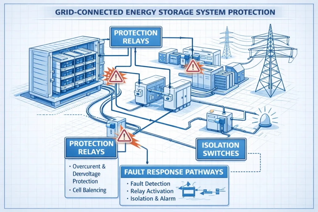
A short circuit on the grid side of a BESS behaves nothing like one on the DC bus. IEC 60909 is the standard engineers use to calculate that AC-side fault current.
It also sizes the breakers, relays, and busbars on the grid-facing side of the system.
Quick Answer IEC 60909 is the IEC standard for calculating short-circuit currents in three-phase AC systems. Its current edition, IEC 60909-0:2016, added rules for how inverter-connected sources like BESS and solar contribute to a fault. So this update matters directly for grid-interconnection and protection-coordination studies.
What Is IEC 60909?
The standard covers short-circuit current calculation in three-phase AC systems, both low-voltage and high-voltage. IEC Technical Committee 73 develops it, and that’s a detail worth knowing.
That’s the same committee behind IEC 61660, the DC-side equivalent for auxiliary systems. So the two standards share a family resemblance, and not by accident.
The current edition, IEC 60909-0:2016, replaced a 2001 first edition. It’s a full technical revision, not just a minor tweak.
First, the method places an equivalent voltage source at the fault location. Engineers then work out the fault current from that source. They add the impedance of every AC component between it and the fault point.
IEC 60909’s Maximum and Minimum Short-Circuit Current
Like IEC 61660, IEC 60909 calls for two separate calculations, not one. First, the maximum short-circuit current sets equipment ratings.
The minimum short-circuit current does something different. It sets fuse and relay ratings, and it also checks whether protection will trip fast enough during a fault.
Each case runs on its own assumptions, since network configuration and available sources both shift the result.
How IEC 60909 Models Fault Current Sources
IEC 60909 walks through nearly every source type on an AC system. That list covers network feeders, transformers, overhead lines and cables, synchronous generators, and asynchronous motors.
Each source then gets its own impedance model and its own share of the total fault current.
A network feeder is modeled first, using the utility’s own maximum and minimum short-circuit power at the connection point.
Then transformers, cables, and lines each add their own resistance and reactance in series. This works outward from that feeder toward the fault.
Traditional generation still dominates most of this picture. First, a synchronous generator can feed many times its rated current into a nearby fault.
That’s because the fault current is limited mainly by the machine’s own internal reactance, not by any active control.
Picture a substation fed by a large synchronous generator on one side and a smaller BESS on the other. A fault right at the busbar draws heavily from the generator, since its current is bounded only by internal reactance.
The BESS contributes too, but through a very different mechanism, covered next.
Asynchronous motors matter here too, since they aren’t purely passive. Large motors briefly feed current back into a nearby fault as they slow down. So the standard includes a separate check for whether that contribution is large enough to count.
Why the 2016 Edition of IEC 60909 Matters for BESS
IEC 60909’s 2016 edition made a genuinely significant change. It added explicit rules for wind power station units and for power station units with full-size converters. Neither type existed in any meaningful way when the 2001 edition published.
A BESS, meanwhile, connects to the grid through exactly this kind of full-size converter: the PCS. So this update is what actually lets engineers model a BESS’s AC-side fault contribution under a current, recognized standard.
Before 2016, engineers had to adapt rules meant for generators instead, which is a poor fit for how a PCS actually behaves.
How a BESS Contributes to an AC Fault
#image_title
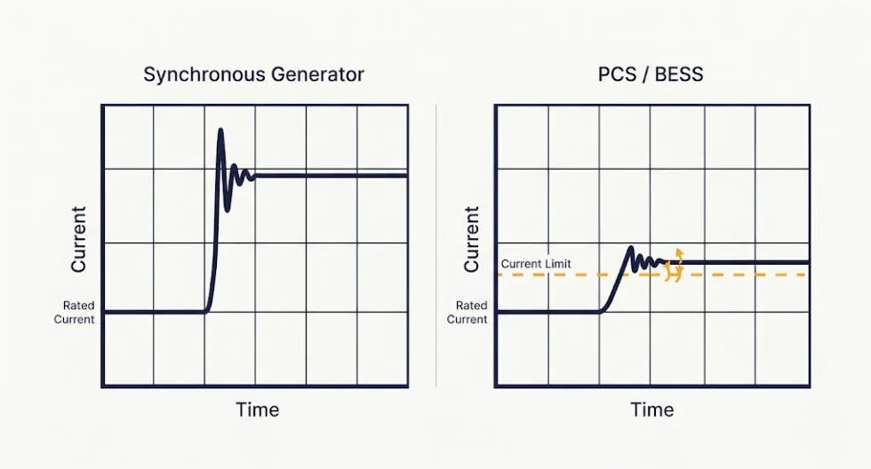
A synchronous generator’s fault current is set by its impedance, not by any active control loop, while a PCS works on a different principle entirely. It behaves very differently.
Since the PCS is a power-electronic device, its control system actively regulates the fault current it can push out. IEC 60909 treats it as a current-regulated source instead of an impedance-limited one.
So that current stays capped close to the converter’s own rated current. It doesn’t spike the way a generator’s current can, because the control loop won’t let it.
What This Means for Protection Coordination
This distinction then has real consequences for a project. A feeder fed mostly by BESS and solar can produce far less fault current. That’s true even compared with the same feeder fed by traditional generation.
Many protection schemes were designed around large, generator-driven fault currents. So a low-fault-current feeder can be harder to detect and clear quickly. Under-reach becomes a real risk once the fault current gets close to normal load current.
IEC 60909-0:2016 gives engineers a standards-based way to calculate that lower contribution accurately. That’s a real improvement over guessing at it or borrowing a generator-based rule of thumb.
It’s also why relay settings tuned for a generator-heavy feeder often need a fresh look once a BESS joins the mix.
IEC 60909 vs. Related Standards
IEC 60909 doesn’t work alone on a BESS project. But a few related standards cover adjacent ground.
Standard
Relationship to IEC 60909
IEC 61660
The DC-side equivalent, covering short-circuit currents in DC auxiliary systems instead of the AC side. Both standards come from the same technical committee.
IEC 62933-5-2
The BESS safety standard, which addresses electrical safety more broadly rather than fault-current calculation methodology specifically.
IEEE 2800-2022
A newer, US-focused standard for interconnecting inverter-based resources, covering performance requirements alongside fault behavior.
The IEC 61660 connection is worth calling out directly. A full BESS fault study often needs both — this standard for the grid-facing AC side, and IEC 61660 for the battery-facing DC side.
What This Means for BESS Grid-Interconnection Studies
For a project engineer, IEC 60909-0:2016 is the tool for AC-side protection coordination and utility interconnection studies. First, model the PCS as a current-regulated source, not a synchronous one.
A BESS project often sits on a feeder alongside other inverter-based generation, like solar. So check the combined fault contribution rather than treating each source alone. Utilities reviewing an interconnection application will still expect exactly this kind of AC-side study.
Frequently Asked Questions
Does IEC 60909 apply to battery energy storage systems?
Yes, through its current edition. IEC 60909-0:2016 added specific rules for power station units with full-size converters, covering how a BESS’s PCS contributes to an AC-side fault.
What’s the difference between IEC 60909 and IEC 61660?
This standard calculates short-circuit currents on the AC side of a system. IEC 61660 covers the DC side instead, such as the battery and busbar side of a BESS.
Why does a BESS contribute less fault current than a generator?
A PCS is a current-regulated power-electronic source, not an impedance-limited one. Its control system caps the fault current close to its own rated current, unlike a synchronous generator.
Is IEC 60909-0:2016 the current edition?
Yes. It replaced the 2001 first edition and remains the standard’s current edition as of 2026.
Who uses IEC 60909 on a BESS project?
Protection engineers and utility interconnection teams use it for AC-side fault current, breaker and relay sizing, and protection coordination studies.
A short circuit on a DC bus behaves very differently from one on an AC grid. IEC 61660 is the standard engineers use to calculate those DC fault currents in battery storage systems and substations. That way, protection devices get sized right.
Quick Answer IEC 61660 is a three-part IEC standard for calculating short-circuit currents on DC auxiliary buses. It covers rectifiers, batteries, capacitors, and DC motors. BESS engineers still use it today, even though it predates lithium-ion and was written for lead-acid batteries.
What Is IEC 61660?
IEC 61660 first appeared in 1997. Its full title is “Short-circuit currents in d.c. auxiliary installations in power plants and substations.” IEC Technical Committee 73 developed it. That same committee owns IEC 60909, the equivalent standard for AC systems.
The standard exists because DC faults don’t behave like AC ones. An AC fault current oscillates and decays in a set way.
A DC fault current rises and falls on its own curve instead. Each source shapes that curve in its own way.
IEC 61660-1 is still listed by the IEC as active and current, even though no revision has replaced it since 1997.
This matters for BESS design. Every battery rack, busbar, and DC disconnect on the storage side of the inverter sits on a DC bus.
So when a fault happens there, protection devices must clear a current whose shape this standard was built to predict.
The Three Parts of IEC 61660
The standard is split into three linked documents. Each one covers a different piece of the fault-current picture.
Part
Title
What It Covers
Part 1
Calculation of short-circuit currents
The core method: peak current, quasi-steady-state current, and how to combine several sources
Part 2
Calculation of effects
Mechanical and thermal stress on rigid conductors and busbars, caused by the current from Part 1
Part 3
Examples of calculations
A technical report with worked examples, so engineers can check their own math against a known result
Part 1 does the heavy lifting for most BESS projects. From there, Part 2 turns that current into a mechanical design check, while Part 3 serves as a reference for checking the numbers.
Part 3 wasn’t even finished when Part 1 published in 1997. The original foreword lists it as “in preparation,” and it only appeared a few years later as a technical report.
How IEC 61660-1 Calculates DC Short-Circuit Current
Two values matter most to a protection engineer.
Two Values That Matter: Peak and Quasi-Steady-State Current
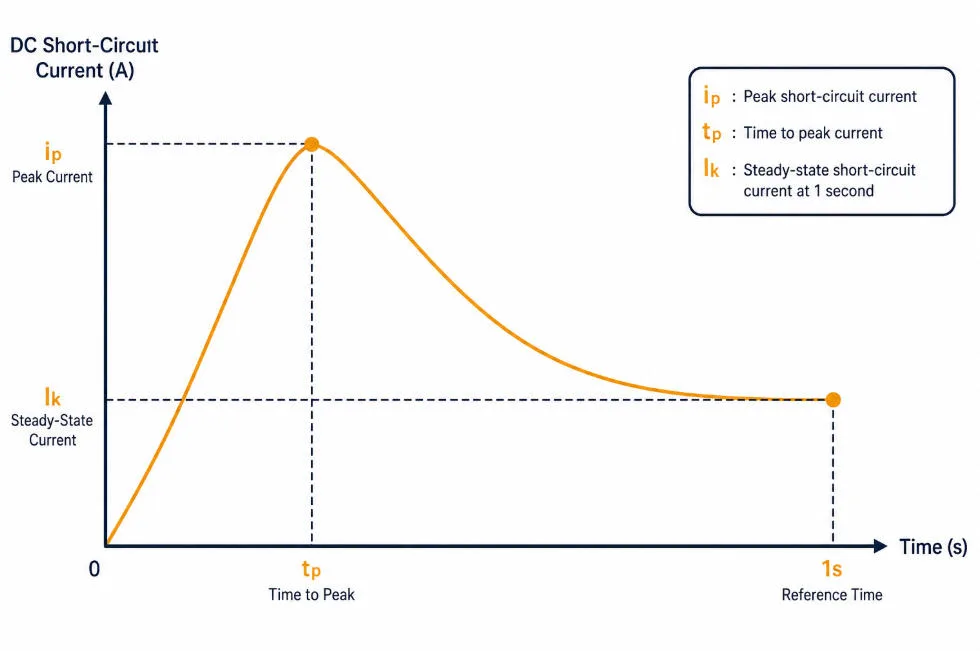
The peak short-circuit current, written as ip, is the highest instant current a fault ever reaches. So this value sets the rating for breakers, fuses, and busbars, since they must survive that first spike without failing.
The quasi steady-state current, written as Ik, is the current level one second after the fault starts.
Engineers then use this lower, settled value to set fuse and relay trip points, since it reflects what a slower device actually has to clear.
Between those two points sits the time to peak, tp. It tells engineers how fast the current climbs before it starts to fall.
Maximum and Minimum Short-Circuit Current
The standard actually calls for two separate calculations, not one. For equipment ratings, engineers work from conditions that produce the highest possible fault current: cooler conductor resistance and a fully charged battery.
For fuse and protection settings, they work from conditions that produce the lowest fault current instead: conductor resistance at the system’s maximum operating temperature, and a battery closer to fully discharged. Each case still has its own peak and quasi-steady-state current, so a full study runs through both.
Four Sources of DC Fault Current
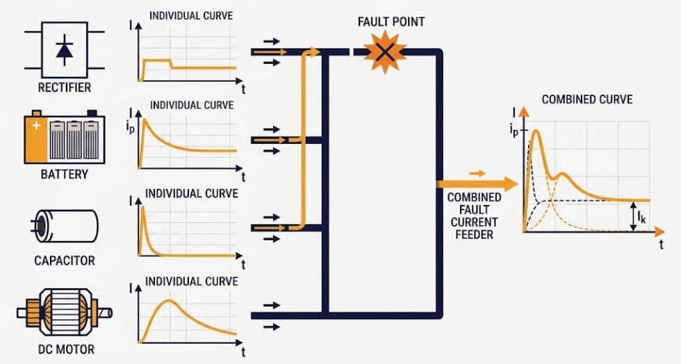
The method models four types of equipment that can feed a DC short circuit:
Rectifiers in a three-phase AC bridge connection
Stationary lead-acid batteries
Smoothing capacitors
DC motors with independent excitation
Each source has its own current shape. A rectifier’s fault current follows the AC network behind it.
Meanwhile, a battery’s current rises with a time constant set by its own resistance and inductance, and a capacitor discharges fast, then decays.
A motor is different again, since it keeps feeding current for a short time while its stored mechanical energy converts back into electrical energy.
When more than one source can reach the same fault point, a correction factor (the standard calls it sigma) combines their peaks into one worst-case total. This matters because the individual peaks don’t always line up in time.
Picture a substation battery room with a rectifier charger and a battery bank feeding the same DC bus. The rectifier’s current might peak in a few milliseconds, while the battery’s current keeps climbing for longer, since its inductance slows the rise. Because of that timing gap, the correction factor keeps the combined peak from being just a simple sum of two separate maximums.
Why IEC 61660 Still Matters for Lithium-Ion BESS
The standard was written in 1997, years before lithium-ion reached grid-scale storage. That gap still matters for BESS engineers today.
The Lithium-Ion Gap
The battery clause only models stationary lead-acid cells, and it gives no official method for lithium iron phosphate or other lithium-ion chemistries. So a literal reading of the standard doesn’t cover the battery technology in most BESS projects built today.
How Engineers Work Around It Today
In practice, the industry leans on two workarounds.
First, many engineers treat a lithium-ion string’s short-circuit response like a capacitor discharge. Both show a fast spike, then a decay, and the standard already has a capacitor method built in.
Second, most BESS integrators pull short-circuit current data straight from the cell or rack maker’s datasheet. They then feed those figures into the rest of the calculation, alongside the rectifier and capacitor terms.
Commercial short-circuit analysis software built around this method now adds lithium-ion battery models as an extension beyond the base document. Engineers keep the same combination approach while plugging in a chemistry-correct source model.
IEC 61660 vs. Related DC and BESS Standards
This standard doesn’t work alone, since a few other documents reference it or cover nearby ground.
Standard
Relationship to IEC 61660
IEC 60909
The AC equivalent. This standard’s own foreword names IEC 60909 as a companion reference for the rectifier’s AC-side contribution.
The BESS safety standard covers electrical safety more broadly, including how DC-side fault-current figures feed into protection design.
IEC 62619
Covers cell and battery safety testing rather than system-level fault current, so it complements this standard instead of overlapping it.
What This Means for BESS DC Bus Protection Design
For a project engineer, the takeaway is simple: first, size DC breakers and busbars to the peak current, ip.
Set fuse and relay trip points from the quasi-steady-state current, Ik. Then combine every source that can feed the same fault point, not just the battery.
Since the method predates lithium-ion, document which battery-current approach the design used. Note whether it was capacitor-equivalent modeling or manufacturer datasheet figures, so the calculation can be reviewed and repeated later.
Also check Part 2 once the current is known. A busbar sized only for steady-state load current can still fail mechanically under a DC fault it was never checked against.
Frequently Asked Questions
Does IEC 61660 apply to lithium-ion BESS?
Not directly, since the battery clause only covers stationary lead-acid batteries. Engineers commonly adapt the capacitor model instead, or use manufacturer-supplied short-circuit data for lithium-ion strings.
What’s the difference between IEC 61660 and IEC 60909?
IEC 60909 calculates short-circuit currents in three-phase AC systems. This standard calculates them on the DC side instead, where fault currents don’t oscillate and decay the same way.
Is there a newer edition of IEC 61660?
The first edition dates to 1997, with corrigenda issued in 1999 and 2000. Even so, no second edition has replaced it as of 2026.
What does Part 2 cover that Part 1 doesn’t?
Part 1 calculates the fault current itself, while Part 2 uses that current to calculate the mechanical and thermal stress it puts on rigid conductors and busbars.
Who uses IEC 61660 in a BESS project?
Protection and electrical engineers use it to size DC breakers, fuses, and busbars during the design phase, well before commissioning.
IEC 61660-1:1997, Short-circuit currents in d.c. auxiliary installations in power plants and substations – Part 1: Calculation of short-circuit currents. International Electrotechnical Commission (with Corrigenda 1:1999 and 2:2000).
IEEE Industry Applications Society, “DC Arc Flash: History, Physics, and Modeling for Battery, Capacitor, and PV Systems,” first presented at the IEEE Electrical Safety Workshop (ESW) 2023 — covers DC incident-energy modeling approaches for large battery systems, including lithium-ion, and their relation to standards-based short-circuit current models.
MCS certification is the UK’s benchmark for quality in small-scale renewable energy. Since 2007, it has set the standards for solar panels, battery storage, and heat pumps. A product or installer must meet those standards to earn the MCS mark. For homeowners, that mark is often the difference between a government grant and no grant at all.
Quick Answer MCS certification is the UK’s quality mark for small-scale renewable energy. It covers solar PV, battery storage, heat pumps, solar thermal, biomass, and wind. MCS certifies both the products and the installers who fit them. Most UK government incentives, including the Smart Export Guarantee and Boiler Upgrade Scheme, require it.
What Is MCS Certification?
MCS stands for Microgeneration Certification Scheme. It is a UKAS-accredited quality scheme. It covers small-scale, low-carbon energy technologies in UK homes and small businesses.
The scheme works on two levels at once. First, it certifies products, while also certifying the businesses that install them. A solar panel, battery, or heat pump must pass independent testing first. Only then can it carry the MCS mark. Second, it certifies installers. The business that fits the system must also meet set technical and consumer-protection standards.
Both halves matter together. A certified product fitted by an uncertified installer will not earn an MCS certificate. Nor will a certified installer using an uncertified product.
The scheme is owned by the MCS Charitable Foundation, a registered charity. It is run day to day by The MCS Service Company Ltd. Independent certification bodies carry out the actual assessments. These bodies hold UKAS accreditation to ISO 17065.
A Brief History of the Scheme
MCS launched in 2007, backed by the UK government. At the time, the microgeneration market was growing fast but had little oversight. The scheme brought a common set of rules to that market.
Early adoption came from the Feed-in Tariff and Renewable Heat Incentive. Both required MCS-certified equipment and installers to qualify for payments.
Although those two schemes have since closed, the certification framework has grown alongside the newer incentives that replaced them. Battery storage joined the scheme in 2020, with its own dedicated installation standard. That change reflects how central storage has become to UK home energy.
Through 2026 and into 2027, MCS is rolling out its biggest change since launch. This is a redeveloped installer scheme, covered later in this guide.
What Technologies Does MCS Certification Cover?
MCS certification spans seven core technology groups. Together, they cover most of the low-carbon systems a UK household is likely to install.
Solar PV — rooftop and ground-mounted panels that generate power
Battery storage — electrical energy storage systems (EESS) that store solar or grid power for later use
Air and ground source heat pumps — low-carbon heating and hot water
Solar thermal — panels that heat water directly from sunlight
Biomass — wood-fuelled boilers and stoves
Wind turbines — small-scale wind power for homes and small firms
Micro-hydro — small water-driven electricity generation
How MCS Certification Works
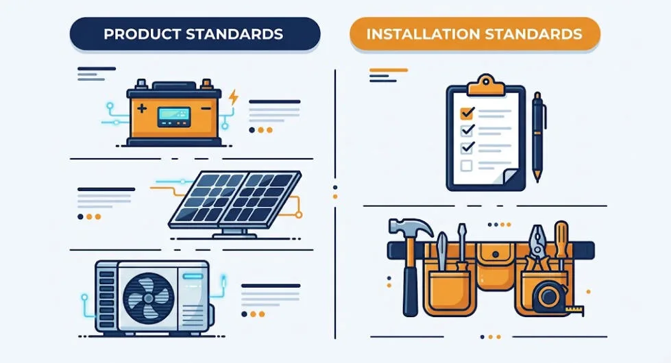
Every technology under the scheme follows two linked sets of rules. One is a product standard. The other is an installation standard. Together, they explain why both the equipment and the company fitting it need to carry the mark.
Product Standards
Product standards set out performance and safety tests for a given technology. MCS 005, for example, covers solar PV modules. On top of that, every manufacturer must also meet MCS 010, a shared factory quality-control standard that applies across all product types. Consequently, a manufacturer submits its product for independent testing first. Only then does it appear on the MCS certified products list.
Installation Standards
Installation standards are published as MCS Installation Standards (MIS) documents. They define how an installer must design, size, and commission a system on site. They cover everything from electrical safety to customer handover paperwork.
An installer’s work is checked in several ways. Certification bodies run technical checks, sample audits, and site visits. Most of this happens on a rolling annual cycle.
MCS Certification for Battery Storage
Battery storage sits inside the same certification framework as solar and heat pumps. It has its own installation standard, though: MIS 3012. First piloted in 2020, and updated since, it covers residential and small commercial systems up to 50kW.
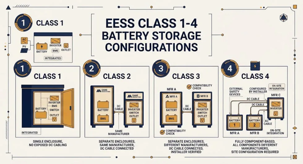
MIS 3012 sorts battery installations into four classes. MCS calls these Electrical Energy Storage System (EESS) classes. The class depends on how the battery, inverter, and safety devices are packaged. It also depends on how many manufacturers supplied them. This classification decides which compatibility checks an installer must run before commissioning.
For a broader look at how storage certification standards work outside the UK residential market, see our guide to BESS certifications.
MIS 3012 also adds UK-specific requirements on top of general battery safety practice. These cover DC isolation, fire and ventilation guidance, and mandatory customer documentation at handover.
Why MCS Certification Matters for Homeowners and Installers
MCS certification is not a legal requirement. You can install a solar panel, battery, or heat pump without it. In practice, though, it is very hard to access UK government incentives without the certificate.
Smart Export Guarantee
The Smart Export Guarantee pays households for electricity they export to the grid. To qualify, an MCS certified installer must install the system. The products used must also be MCS certified. A smart meter that records exports is required too.
Boiler Upgrade Scheme
The Boiler Upgrade Scheme is run by Ofgem on behalf of DESNZ. It offers grants of up to £7,500 towards an air or ground source heat pump. Biomass boilers can get up to £5,000. Both the installer and the heat pump must carry MCS certification for the grant to pay out.
Other Incentives and Protections
The certificate also underpins eligibility for ECO4 and the Home Energy Scotland Grant and Loan, sitting alongside 0% VAT benefits on qualifying installations. Beyond the money, certified installers owe customers real protections. These include a written quote, a minimum workmanship warranty, and free access to dispute resolution if something goes wrong.
The Redeveloped MCS Installer Scheme
MCS is in the middle of its biggest overhaul since launch. Consultation began in 2022 and 2023. The redeveloped installer scheme then started rolling out to installers in early 2026. MCS has set a target completion date of 31 March 2027.
The new scheme shifts focus. It moves away from paperwork-heavy quality management systems. Instead, it looks at the quality of the finished installation on site. Three named business roles now sit at the centre of every certified installer. A Licensee holds ultimate responsibility for meeting scheme requirements. The Main Contact handles day-to-day contact with MCS and the certification body. A Technical Supervisor then signs off that each job meets the relevant installation standard.
Track record now shapes how often an installer gets checked. Installers with a strong, consistent record face fewer site assessments. Those with more issues get checked more often. Every installer must also buy an MCS-approved financial protection product for each customer. This gives homeowners a safety net if an installer cannot fix a problem itself.
How to Check MCS Certification
Checking a company’s MCS certification takes under a minute, and it is free. Search the public installer database on the MCS website. Or look up a specific job on the MCS Installations Database, at certificate.microgenerationcertification.org.
Before signing a contract, confirm three things. First, check the installer’s certification is current. Second, check the exact product model sits on the MCS certified products list. Third, check the installer’s certification covers the technology you are buying. An installer certified for solar PV is not automatically certified for battery storage. Each technology sits under its own installation standard.
Key Takeaways
MCS certification is the UK’s main quality mark for solar PV, battery storage, heat pumps, solar thermal, biomass, and wind.
It certifies products and installers separately. A valid MCS certificate needs both.
It is not a legal requirement, but it is required for the Smart Export Guarantee, Boiler Upgrade Scheme, and ECO4..
Battery storage has its own installation standard, MIS 3012, covering systems up to 50kW.
A redeveloped installer scheme is rolling out through 2026 and 2027, with new business roles and mandatory financial protection.
Frequently Asked Questions
Is MCS certification a legal requirement?
No. You can install a solar panel, battery, or heat pump without it. You will not, though, qualify for the Smart Export Guarantee, the Boiler Upgrade Scheme, or related regional grants.
How long does certification last?
It is ongoing, not a one-off event. Certification bodies run regular audits, usually once a year. An installer can lose certification for failing to meet the standard.
Does MCS cover standalone battery storage?
Yes. MIS 3012 covers battery storage added to an existing solar system. It also covers battery-only installations with no solar panels at all.
What happens with a non-MCS installer?
The work may still be safe and good. It will not, though, generate an MCS certificate. Without that certificate, the property cannot access MCS-linked grants or export payments, even later.
Learn More From MCS
For the full list of current standards, certified installers, and certified products, see the official MCS website, which maintains the live installer and product databases referenced throughout this guide.
IEC 62619 is the international safety standard that most industrial and commercial BESS suppliers get asked for first. Cell datasheets cite it, and procurement checklists demand it. But the standard rarely gets explained beyond a single bullet point in a longer certifications guide. So this article breaks down what it tests. It also covers what changed in the current edition, and how it fits alongside UL 1973 and IEC 63056.
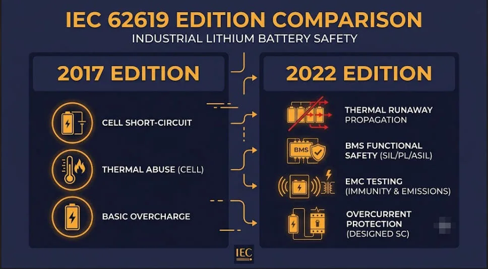
Quick Answer IEC 62619:2022 is the international safety standard for rechargeable lithium cells and batteries in industrial applications. It covers stationary uses like BESS, UPS, and telecom backup, plus motive uses like forklifts and AGVs, but excludes road vehicles and consumer devices. The current edition added mandatory thermal runaway propagation testing, a formal BMS safety analysis, EMC testing, and overcurrent protection checks.
What Is IEC 62619?
IEC 62619 is published by the International Electrotechnical Commission’s Subcommittee 21A. Its full title is long, but in short: safety rules for lithium cells and batteries used in industry. The standard sets out the tests needed to show a lithium cell or battery is safe. This applies under both normal use and fault conditions.
The scope is industrial, not consumer. So it covers two broad groups:
Stationary applications — telecom power, uninterruptible power supplies (UPS), electrical energy storage systems, utility switching, and emergency power
Road vehicles are excluded. Where a conflict exists, standards written for automotive traction batteries take precedence instead (the IEC 62660 series). Consumer and portable devices sit under a separate standard, IEC 62133-2, rather than this one. For electrical energy storage systems, suppliers often pair IEC 62619 with a companion standard, IEC 63056. That standard adds rules built for EESS use. More on that distinction below.
The current edition is IEC 62619:2022 (Edition 2.0, published 24 May 2022). It replaced the original 2017 first edition. Europe adopts it through the EN and BS EN routes. Companies also often use the standard alongside CE marking for industrial battery systems.
What Changed Between the 2017 and 2022 Editions
The second edition of IEC 62619 is a meaningfully stricter document. It is not a light refresh. Instead, the main additions concern system-level safety, not cell chemistry. This shift reflects how the industry moved from single-cell risk toward large multi-cell BESS deployments between 2017 and 2022.
Area
What Changed in the 2022 Edition
Thermal runaway propagation
Became a mandatory test. It was present informally since 2017 but is now formalized and expanded. A new laser-ignition method was added as an alternative trigger.
BMS functional safety
New rule for a formal safety analysis of the BMS. This references frameworks such as IEC 61508 (targeting SIL-2) or ISO 13849.
Overcurrent protection
New test checking that circuit protection triggers correctly under abnormal charge or discharge current.
Electromagnetic compatibility (EMC)
New rule showing BMS protection functions aren’t disrupted by outside electromagnetic interference.
System locks / fail-safe states
Clarified rules for preventing an unsafe automatic restart after a fault.
What the Standard Actually Tests
IEC 62619 testing runs across four categories: electrical, mechanical, environmental, and system-level. First, cell-level tests confirm the chemistry and build are safe. Then, system-level tests take over — newer and heavier in the 2022 edition. Together, they confirm the battery and its BMS respond correctly when something goes wrong.
Electrical Safety Tests
Overcharge — the test charges the cell or battery to roughly 1.5x rated voltage for an extended hold. No fire or explosion may occur. This shows the protection circuit or BMS cuts off correctly.
External short circuit — the test shorts the terminals through a low-resistance path. Surface temperature must stay well below thermal-runaway onset.
Forced discharge — the test discharges the battery below its minimum voltage, then checks for safe behaviour and a minimum capacity recovery on recharge.
Overcurrent protection (2022 addition) — shows the protection circuit activates correctly under abnormal charge or discharge current.
Mechanical and Environmental Tests
Crush — the test applies a defined force to the battery face. No fire or explosion may occur.
Free fall — drop testing across several orientations onto a hard surface. Checks for electrolyte leakage, fire, or explosion.
Vibration and shock — simulates transport and in-service stress without loss of function.
Temperature cycling — repeated cycling across a wide temperature band. A minimum capacity retention threshold applies at the end.
Thermal abuse — external heating beyond the maximum rated temperature. Evaluates the failure response.
System-Level Safety Tests
This is where the 2022 edition diverges most from 2017. Instead of behaving like a cell-safety spec, the standard now reads more like a system-safety framework.
Thermal runaway propagation — the test deliberately drives a single cell into thermal runaway, then checks the failure doesn’t spread to neighbouring cells. This test matters most for large-format BESS design, since isolated cell failures inside a multi-megawatt-hour system count as a near-certainty over a 15-20 year service life. The goal is a contained, graceful failure, not zero failures.
BMS functional safety analysis — the test checks the BMS against a recognised safety framework. Triple monitoring of voltage, current, and temperature is typical at cell or module level, plus fast auto-disconnect on fault.
Communication fault handling — the system must enter a safe state if it loses BMS-to-host communication.
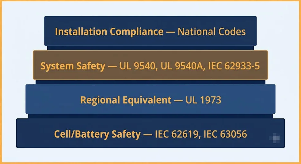
IEC 62619 rarely sits alone on a certification checklist. It’s one layer in a stack. That stack spans cell chemistry, system safety, installation, and transport. Here’s how it maps against the standards it’s most often confused with. This comparison draws on the IECEE CB Scheme documentation that governs how these certificates get issued and recognised worldwide.
US stationary and motive auxiliary power battery safety
Regional equivalent for the US market. Most North American stationary ESS installs require UL 1973 specifically, so global suppliers often hold both UL 1973 and this standard.
IEC 63056
Safety rules for secondary lithium batteries used in electrical energy storage systems
A companion standard, not a substitute. This standard sets the general industrial baseline, while IEC 63056 layers on EESS-specific rules. So ESS suppliers are often asked for both.
System- and grid-level safety for electrical energy storage systems
Sits above IEC 62619 in the stack. This standard certifies the cell or battery product, then IEC 62933-5 covers safety once that battery joins a full grid-connected system.
Safety of power converters (PCS/inverters) used in PV and ESS
Covers the inverter side, not the battery. This standard and IEC 62109 are complementary, since a full system needs certified batteries and a certified PCS.
Certification vs. Installation Compliance
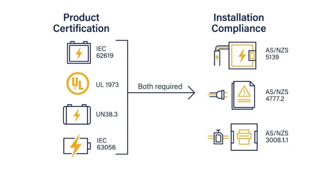
One point worth remembering: this standard tests the battery product itself. It says nothing about whether an installation is legal in a given country. In Australia, for example, a certified battery module still has to separately satisfy AS/NZS 5139 for installation safety, AS/NZS 4777.2 for inverter compliance, and AS/NZS 3008.1.1 for cable sizing. So, product certification and installation compliance are two different layers. See our full breakdown in Australia’s New Battery Rules: The 2026 Compliance Stack.
Who Needs IEC 62619 Certification
Commercial & industrial (C&I) BESS makers and integrators
Utility-scale energy storage suppliers
Telecom backup power and UPS system makers
Industrial motive power — forklifts, AGVs, and similar equipment
Residential/home ESS suppliers — this standard is often part of the certification stack here too, though household rules sometimes point to IEC 60335 or IEC 63056 instead
Buyers should ask for cell-and-pack-level certification specifically. A component-level test report from one sub-supplier is not enough, since system integration, BMS logic, and enclosure design all affect whether certified parts stay safe once assembled.
Regional Recognition
Region
How It Is Recognised
International (CB Scheme)
50+ member countries accept test reports and certificates issued under the IECEE CB Scheme. This avoids duplicate testing when entering multiple markets.
Europe
Europe uses EN IEC 62619:2022 / BS EN IEC 62619:2022. Manufacturers commonly cite it for CE marking under the Low Voltage Directive.
India
IS 17855:2022 aligns closely with this standard. Large utility and industrial BESS tenders require it. Testing must happen at BIS-approved labs or accredited labs with a BIS agreement.
China
GB/T 36276 is the primary domestic standard for lithium-ion energy storage batteries. This standard is used as the international equivalent instead, for export-facing products.
Australia & New Zealand
One of the battery certifications commonly requested, alongside UL 1973 and UN 38.3. But it does not replace AS/NZS 5139 installation compliance — see our Australia battery rules hub for the full stack.
The Certification Process, in Brief
IEC 62619 certification typically runs through the IECEE CB Scheme:
Submit the application to an IECEE-recognised National Certification Body (NCB) with product docs, cell/battery specs, and BMS design details
The lab tests samples at an accredited CB Test Laboratory (CBTL) against the full test matrix
The lab issues a CB Test Report (CBTR) and CB Test Certificate (CBTC) on success
The CB certificate then converts into national certificates (CE, KC, SAA, and others). This is usually faster than a fresh national bid, since it draws on the existing CB test report
Timelines vary by scope and lab backlog. Full testing commonly runs several weeks to a few months. This depends on sample availability and whether early testing surfaces issues that need a redesign. So, ask suppliers for the CB Test Certificate itself and the full test report. Also confirm which edition, 2017 or 2022, it references. The 2022 edition is now the one expected for new product submissions.
IEC 62619 Compliance Checklist
Check the certificate references IEC 62619:2022, not the superseded 2017 edition
Request the full CB Test Report, not just the summary certificate
Verify the submission includes thermal runaway propagation results — this test matters most for multi-cell BESS safety
Check the BMS has a functional safety analysis (IEC 61508 SIL-2 or ISO 13849) in the submission
Check whether the application also needs IEC 63056 certification for the specific EESS use
For the US market, confirm whether the market requires UL 1973 too
Don’t treat this standard as a stand-in for system-level or installation rules. Check UL 9540/9540A, IEC 62933-5, or the local installation code separately
For transport, confirm the supplier holds UN 38.3 certification separately — this standard doesn’t cover it
Frequently Asked Questions
Is IEC 62619 mandatory?
IEC 62619 is a voluntary international standard, not a law. But it’s mandatory in practice across most industrial and utility-scale BESS procurement. Buyers, insurers, and financiers routinely list it as a minimum requirement, and some national tenders, including large BESS tenders in India, name it directly as mandatory.
Does IEC 62619 cover the whole BESS system or just the battery?
It covers the cell and battery product, including its BMS. But it does not cover the full assembled system. Enclosure design, fire suppression, inverter safety (IEC 62109), and grid-level integration (IEC 62933-5) all sit outside its scope.
What’s the difference between IEC 62619 and IEC 63056?
IEC 62619 sets general industrial safety rules for lithium cells and batteries. IEC 63056, meanwhile, is a companion standard with rules specific to electrical energy storage use. So suppliers commonly hold both together, not as alternatives.
Do I need both IEC 62619 and UL 1973?
Only if the product sells into both international and US markets. UL 1973 is what US utilities, AHJs, and insurers expect for stationary ESS, while IEC 62619 is the equivalent almost everywhere else. So global suppliers commonly hold both.
What was the biggest change in the 2022 edition?
The mandatory thermal runaway propagation test, plus the new rule for a documented BMS safety analysis. Both reflect the shift from single-cell risk thinking toward large, multi-cell stationary BESS.
AS/NZS 4777.2 Amendment 2 changed how Australia approves grid-connect inverters. Standards Australia published it on 23 August 2024. It became mandatory exactly one year later. Also, it now applies to every new grid-connect install. So any inverter installed today needs to meet it. So this guide covers every real change. It also covers the region settings you need to check, and what happened to inverters already on the approved list. It’s one of three standards in Australia’s new battery rules.
Quick Answer Quick answer: It became mandatory on 23 August 2025, after a 12-month transition. It makes six changes. New supply terms. Fewer tests for battery-only gear. New generation limit rules. Updated Region C set points. New paperwork rules. New clauses for two-way EV charging. Older CEC inverter listings didn’t carry over automatically. So manufacturers had to submit a declaration and evidence of the updated region settings before the deadline, or their models came off the approved list.
What Is AS/NZS 4777.2 Amendment 2?
AS/NZS 4777.2 is the standard that governs how grid-connect inverters behave once installed. It’s also Part 2 of a two-part standard. Part 1 covers general requirements. Part 2 covers the inverter-specific rules that matter most for design work. AS/NZS 4777.2 Amendment 2 is the second update to the 2020 edition. So it’s formally known as AS/NZS 4777.2:2020 Amendment 2:2024.
The Six Changes in AS/NZS 4777.2 Amendment 2
Six changes make up the bulk of AS/NZS 4777.2 Amendment 2. First, AS/NZS 4777.2 Amendment 2 updates supply type terminology, for clearer alignment with AS/NZS 4777.1. Then second, battery-only products no longer need IEC 62109 testing. That cuts duplicate certification work. Third, generation limit control parameters changed. Fourth, AS/NZS 4777.2 Amendment 2 updates Region C set points. Fifth, documentation and marking rules changed. Sixth, and most talked-about, new clauses cover electric vehicle supply equipment.
Change
What It Means
Supply type terminology
Updated for clearer alignment with AS/NZS 4777.1’s supply-type definitions
IEC 62109 removed
Battery-only products no longer need this testing, cutting duplicate certification work
Generation limit parameters
Control parameters for generation limiting were updated
Region C set points
Updated power quality set points specifically for Region C networks (Horizon Power, TasNetworks, remote Power & Water)
Documentation and marking
Updated requirements for product documentation and equipment marking
EVSE clauses (new)
New clauses covering electric vehicle supply equipment for bidirectional charging
When AS/NZS 4777.2 Amendment 2 Took Effect
So Standards Australia set a 12-month transition window. During that time, manufacturers could apply under the old or the new standard. After 23 August 2025, the Clean Energy Council only accepts Amendment 2 products for new listings. The Clean Energy Council runs this through its approved inverter list. Most network operators use that list directly.
What Happened to Existing CEC Inverter Listings
Existing listings didn’t need full re-testing for AS/NZS 4777.2 Amendment 2. Still, manufacturers had to prove compliance. The Clean Energy Council asked for a signed declaration. It also asked for proof of the updated region settings for every model. That proof could be a product manual, an install guide, or a screenshot from a monitoring app. Anything missing by 23 August 2025 meant the model came off the approved list. The Clean Energy Council’s standards-change page has the full manufacturer declaration template and process.
So this matters for anyone still specifying against an old product sheet. An inverter that was genuinely CEC-approved two years ago may not carry that status today. So always check the live CEC list at the point of design, not a cached copy from a previous project.
CSIP-AUS and Smart Communication
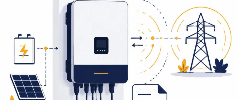
The updated standard introduced CSIP-AUS, the Common Smart Inverter Profile for Australia. Still, this is a communication protocol, not a hardware requirement. It lets network operators manage dynamic export limits, and in some cases apply remote curtailment. A compliant inverter under AS/NZS 4777.2 Amendment 2 lets the grid talk back to it, not just receive power one-way.
Region-Based Power Quality Settings
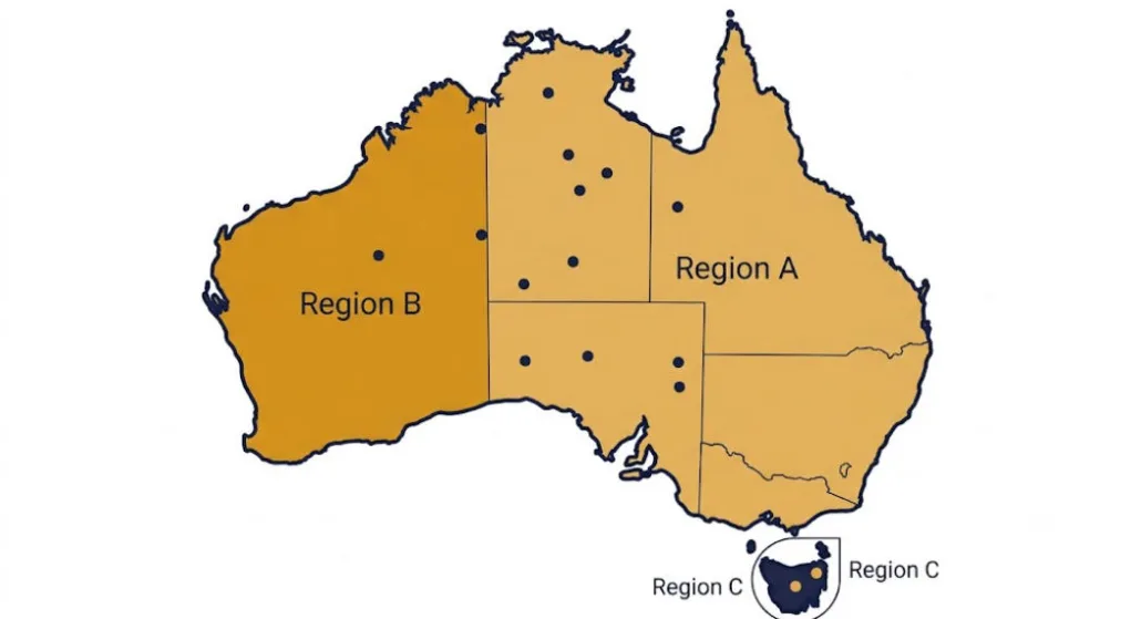
Power quality settings still follow a region-based structure: Australia A, B, or C. Most of the country falls under Region A. Western Power alone makes up Region B. Tasmania and remote areas fall under Region C, covering Horizon Power, TasNetworks, and remote parts of Power & Water. The full list is in the table below. AS/NZS 4777.2 Amendment 2 changed the Region C set points specifically. So a Tasmanian or remote WA install needs extra care here. Energy Networks Australia’s FAQ has the full DNSP contact list for each state.
Region
Distribution Network Service Providers (DNSPs)
Australia A
Ausgrid, AusNet Services, Endeavour Energy, Essential Energy, Ergon Energy, Energex, Evoenergy, Jemena, CitiPower, Powercor, United Energy, SA Power Networks, Power & Water (some areas)
Australia B
Western Power
Australia C
Horizon Power, TasNetworks, Power & Water (remote networks)
Warranty Replacement Rules
Warranty replacements get a narrow exception. Owners can still swap in an older-standard inverter under warranty, but only if three conditions hold together. The replacement has to be the same make and model. It has to genuinely be a warranty case. And the inverter has to match the existing connection agreement. Also, DNSPs still need to approve the replacement first. Outside those conditions, a warranty swap needs a current AS/NZS 4777.2 Amendment 2 compliant unit.
Bidirectional EV Charging: Mode 3 vs Mode 4
Bidirectional EV charging is where this amendment gets genuinely new. It’s not just a terminology refresh. So it splits two charging modes apart. Mode 4 charging sends power to and from the vehicle through wall-mounted gear with its own inverter. That gear now falls under AS/NZS 4777.2 Amendment 2 directly. It also sits inside the CEC’s approved inverter list. Mode 3 also sends power both ways, but the inverter lives inside the car instead. The Clean Energy Council is still working out how much of that setup falls under the same listing rules.
AS/NZS 4777.2 Amendment 2 Compliance Checklist
Confirm the specific inverter model against the live CEC approved list, not a cached spec sheet or marketing page.
Confirm the correct region setting (A, B, or C) for the installation’s DNSP — Region C set points changed under this amendment.
Check whether any EV charging equipment on the job is Mode 3 or Mode 4, since that determines which listing requirements apply.
For battery-only power conversion equipment, confirm whether the IEC 62109 exemption applies to the specific product.
If proposing a warranty replacement with an older-standard inverter, verify all three conditions: same make and model, genuine warranty case, and matching connection agreement.
Get DNSP approval before installing any warranty replacement inverter.
Frequently Asked Questions
When did AS/NZS 4777.2 Amendment 2 become mandatory?
Standards Australia published it on 23 August 2024. After a 12-month transition, it became mandatory for new inverter installations from 23 August 2025.
Does an old CEC inverter listing still work after Amendment 2?
Not automatically. Manufacturers had to submit a declaration and evidence of updated region settings before 23 August 2025. Any model without that evidence was removed from the approved list on that date.
What is CSIP-AUS?
CSIP-AUS is the Common Smart Inverter Profile for Australia — a communication protocol introduced with this amendment that lets network operators manage dynamic export limits and, in some cases, apply remote curtailment.
What’s the difference between Mode 3 and Mode 4 EV charging under this amendment?
Mode 4 charging uses wall-mounted Electric Vehicle Supply Equipment with its own inverter, which falls directly under AS/NZS 4777.2 and the CEC’s approved inverter list. Mode 3 charging also flows power both ways, but the inverter sits inside the vehicle instead — how that gets covered by the listing framework is still being finalised.
Can I still install an inverter that only meets the pre-Amendment 2 standard?
Only as a like-for-like warranty replacement, and only if the replacement is the same make and model, is genuinely for warranty purposes, and is set up to match the existing connection agreement. The DNSP still has to approve it first.
AS/NZS 5139 Amendment 1 changed how batteries get installed across Australia and New Zealand. It arrived on 19 December 2025. So if you designed a BESS install before that date, several of your default assumptions just moved. This guide walks through every real change. New definitions. New clearance figures. A genuinely useful garage exception. A new appendix for fault current calculations. It’s one of three standards in Australia’s new battery rules.
Quick Answer AS/NZS 5139 Amendment 1 updates 18 clauses. It also adds five new figures, plus Appendix I for calculating cell short-circuit current. It’s mandatory now in NSW. Western Australia set a specific deadline of 19 June 2026, after a six-month transition. The headline practical change is a new exception. Batteries can now sit within 600mm of a garage opening wider than 900mm, provided safe egress is preserved.
What Is AS/NZS 5139 Amendment 1?
AS/NZS 5139:2019 is the standard that governs safety for battery energy storage systems. It covers systems connected to power conversion equipment. It replaced the older AS 4086.2 standard back in 2019. AS/NZS 5139 Amendment 1 doesn’t replace this base standard. Instead, it updates specific clauses. It adds new figures. It also adds one new appendix. The rest of the 2019 standard stays in force. The full amended text is available through the Standards Australia Store.
The full clause list is in the table below. It also touches Figures 2.11 and 2.12, and adds five entirely new figures: 4.1A, 4.1B, 4.1C, 4.1D, and 4.2A. Appendix I is new. So is a set of new Bibliography references.
Everything AS/NZS 5139 Amendment 1 Changed, at a Glance
Appendix I — calculating cell short-circuit current
Bibliography
New references added
When AS/NZS 5139 Amendment 1 Takes Effect
Timing isn’t the same in every state. NSW treats the amendment as mandatory right away. Any install that misses the updated requirements no longer complies with the Standard there. WA took a different path. It set a full-compliance date of 19 June 2026, six months after publication. Until then, either the old or the new version is fine. Other states are still working out their own position. So check with your state regulator before you quote a date to a client.
Jurisdiction
Position
Source
NSW
Mandatory immediately on publication (19 Dec 2025)
NSW Building Commission advisory
Western Australia
Full compliance required from 19 Jun 2026, after a 6-month transition where either edition is acceptable
WA Building and Energy notice
Queensland
Amendment issued and communicated to electricians; specific compliance date not published in the source reviewed
WorkSafe QLD eSafe newsletter
Other states/NZ
Not confirmed in this research pass — verify with the relevant state or NZ regulator before quoting a date
—
New Definitions Under AS/NZS 5139 Amendment 1
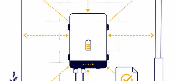
Clause 1.3 covers terms and definitions, and it picked up real changes. The main addition is a new definition: a battery energy storage system room. That’s a dedicated room. It holds the battery, the power conversion equipment, and other BESS accessories. A note attached to this definition matters just as much as the definition. It says a multi-purpose room doesn’t count as “dedicated,” just because a battery sits in it. A garage or a general storage room are both good examples.
Three other definitions picked up clarifying notes too, with practical examples. So electricians should still read Clause 1.3 in full. Drawings and compliance paperwork need to use the amended wording exactly.
New Clearance Figures: 4.1A Through 4.2A
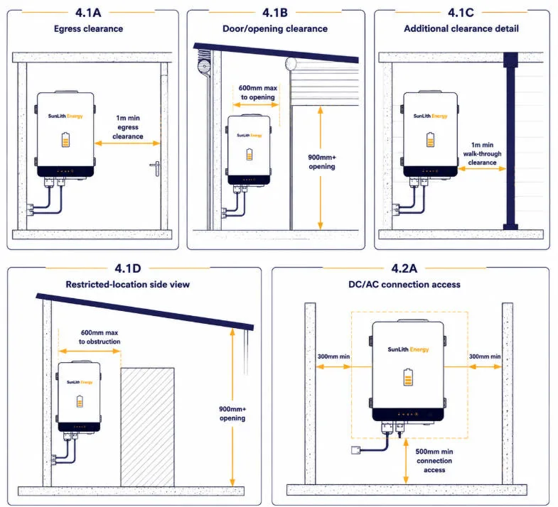
The amendment replaces the old typical BESS installation diagrams with five new figures. First, Figure 4.1A covers egress clearance in a corridor, hallway, or lobby. Then Figure 4.1B covers clearance to doors and openings. Also, Figure 4.1C adds further detail to the clearance picture. Figure 4.1D shows a side-view diagram of clearance from restricted locations, with the familiar 600mm front clearance and 900mm above-battery clearance both drawn out. Finally, Figure 4.2A covers clearances for battery connection access, split by whether the connection is DC or AC.
One structural cleanup came along with the new figures. Also, the standard used to repeat similar diagrams in Section 5. So the amendment removes that duplication. Section 5 now just refers back to the Section 4 figures instead of reprinting them.
The Garage Door Exception — Clause 4.2.2.2
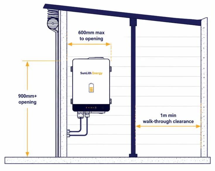
The most talked-about change is a new exception for garage installations. Under the amended Clause 4.2.2.2, a battery can now sit within 600mm of an opening wider than 900mm — a typical garage door, in other words — as long as the opening still allows sufficient clearance for safe egress, and the clearance is no less than 1m from any front or side a person might need to pass through during an exit.
This matters because garages are the preferred spot for a lot of installers. They’re usually not living spaces, they’re weather-protected, often shaded, and close to the switchboard. But the old blanket 600mm rule ruled out a lot of good garage walls, just because of a wide roller door. The amendment keeps the safety goal in place. People still need a safe way out. It just stops punishing a battery for sitting near a large opening when someone could still walk past it safely.
In practice, this means a designer needs two numbers, not one. The first is the 600mm distance to the opening itself. The second is the 1m clearance from whichever front or side edge a person would need to pass. So both conditions have to hold at the same time. A wide garage door with a wall corner narrowing the walk-through space to less than a metre still fails, even if the 600mm figure looks fine on a drawing.
Worked Example
A garage has a 2.4m-wide roller door. The nearest wall section suitable for a battery sits 500mm from the door opening. Under the amended clause, 500mm is within the 600mm allowance, and the door is well over the 900mm width threshold. So far, this passes. But the same wall has a support post 800mm from the door edge, narrowing the usable walk-through space to 800mm at that point. Since 800mm is under the 1m minimum clearance the amendment also requires, this specific layout still fails — even though the headline 600mm number looks fine. Moving the battery, or resolving the post clearance, is the fix.
Inverters as Associated Appliances
The amendment also reclassifies inverters. Power conversion equipment now counts as an associated appliance. So it can go inside a restricted location, where it couldn’t before. That’s a useful change for compact installs, where wall space near the battery is already tight.
Fire Barrier and Overcurrent Protection Changes
Fire barrier requirements moved the other way. Stricter, not looser. So exempt materials used as a barrier to a habitable room now need a minimum thickness of 6mm. Also, building materials within 1 metre of a battery system classed as a chemical hazard pick up new requirements.
Paralleled pre-assembled battery systems get a new rule for overcurrent protection. The protective device’s kA rating now has to cover the combined fault current of every paralleled unit, not just the biggest one. That’s a real change for multi-unit homes and light commercial jobs. Two or three battery modules often get paralleled to hit a target capacity.
To make that calculation possible, the amendment adds Appendix I. It sets out the method for calculating cell short-circuit current within a battery system. So that’s the number a designer needs before sizing the paralleled OCPD correctly. This connects directly to broader short-circuit protection design work on the DC side of a BESS installation. This connects directly to broader short-circuit protection design work on the DC side of a BESS installation.
Safety Data Sheet Requirements
Safety Data Sheet handling picked up a clarification too. A physical copy of the SDS must be provided on site. It also has to stay protected from damage or degradation. The standard specifically mentions storing it in a sealed, durable, clear pouch as an acceptable method. So treat SDS storage as part of the handover package, not an afterthought bolted on at final inspection.
Background: Restricted Locations Under AS/NZS 5139
It helps to know what this amendment did NOT change. The base restricted-location rules still apply. Batteries still can’t sit within 600mm of an exit, a window edge, a vent into a living room, or an appliance. They still can’t sit within 900mm below any of those. Ceiling spaces, wall cavities, roofs, stairways, walkways, escape routes, and living rooms themselves are still off-limits. The ERAC Battery Energy Storage System Guideline backs up these same rules. None of this changed. The amendment only added the wide-opening exception above, plus the inverter reclassification.
Restricted Locations — Unchanged by Amendment 1
Within 600mm of any exit or entry
Within 600mm of any window’s vertical side, or a ventilation opening into a habitable room
In an evacuation or designated escape route
Within 600mm of any appliance
Within 900mm below any of the items above
In ceiling spaces or wall cavities
On roofs
Under stairways or access walkways
Within a habitable room itself
AS/NZS 5139 Amendment 1 Compliance Checklist
Confirm the installation drawings use Clause 1.3’s updated terminology, including the new battery energy storage system room definition.
Check clearance layouts against the new Figures 4.1A–4.2A, not the pre-amendment diagrams.
If relying on the garage-door exception, verify both the 600mm opening distance AND the 1m walk-through clearance — not just one of them.
Confirm inverter placement against the updated associated-appliance classification if it sits in a restricted location.
Check fire-barrier materials meet the 6mm minimum thickness where used as exempt materials.
For paralleled pre-assembled battery systems, recalculate the OCPD kA rating against the combined fault current using Appendix I.
Confirm a physical SDS copy is on site and stored in a protective pouch before handover.
Verify your state’s specific compliance timeline before telling a client the installation is (or isn’t) required to meet Amendment 1 yet.
Frequently Asked Questions
When did AS/NZS 5139 Amendment 1 take effect?
It was published on 19 December 2025. NSW treats it as mandatory immediately. Western Australia requires full compliance from 19 June 2026, after a six-month transition period. Confirm the position in your own state before quoting a date.
What is the garage door exception under this amendment?
Under the amended Clause 4.2.2.2, a battery can be installed within 600mm of an opening wider than 900mm — such as a garage door — provided safe egress is maintained and clearance is no less than 1m from any front or side a person might need to pass through.
Does this amendment change where inverters can be installed?
Yes. Power conversion equipment is now classified as an associated appliance, which means it can be installed inside a restricted location where it previously couldn’t.
What is Appendix I, and what does it calculate?
Appendix I is a new addition that sets out how to calculate cell short-circuit current within a battery system. It’s needed to correctly size overcurrent protection for paralleled pre-assembled battery systems under the amendment’s new kA rating requirement.
Do the pre-existing restricted-location rules still apply under Amendment 1?
Yes, unchanged. Batteries still can’t be installed within 600mm of exits, windows, ventilation openings, or appliances, within 900mm below those items, or in ceiling spaces, wall cavities, roofs, under stairways, escape routes, or habitable rooms. Amendment 1 only added the specific wide-opening exception and the inverter reclassification — it didn’t touch the base restricted-location list.
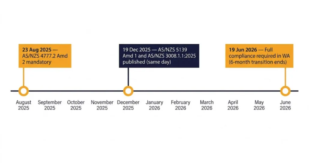
Australia has new battery rules for 2026, and they arrived from three different directions at once. Between August 2025 and December 2025, regulators updated the inverter standard, the battery safety standard, and the cable selection standard. Two of them landed on the very same day. So anyone installing, supplying, or specifying a BESS in Australia now answers to all three of these new battery rules. Miss one, and the other two won’t save the project.
Quick Answer Australia’s new battery rules for 2026 span three standards. AS/NZS 5139:2019 Amendment 1 (published 19 Dec 2025) covers battery system safety. AS/NZS 4777.2:2020 Amendment 2 (mandatory from 23 Aug 2025) governs inverter performance and grid behaviour. AS/NZS 3008.1.1:2025 (also published 19 Dec 2025) sets cable selection and DC ratings. In Western Australia, full compliance with both the 5139 and 3008.1.1 updates is required from 19 June 2026, following a six-month transition period — other states administer their own timelines. A compliant BESS install needs all three standards, and a battery’s international product certifications (IEC 62619, UL 1973, UN38.3) do not substitute for any of them.
What Are Australia’s New Battery Rules?
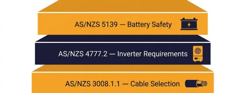
Together, Australia’s new battery rules form what’s best understood as a compliance stack, not three unrelated updates. A battery energy storage system never sits under a single rulebook. Instead, it sits at the intersection of three. AS/NZS 5139 governs how the battery gets installed, ventilated, and protected. AS/NZS 4777.2 governs how the inverter behaves once it talks to the grid. AS/NZS 3008.1.1 governs every cable that connects the two. So a design can pass one standard and still fail the job. Also, it only takes one missed layer to cause it.
It’s also worth separating two things international suppliers often conflate. So battery product certification and Australian installation compliance are not the same thing. A cell or module can carry IEC 62619, UL 1973, and UN38.3 certification and still fail an Australian project if the installation, inverter, or cable design doesn’t separately satisfy the three standards below.
This page works as a living hub, not a one-time post, since Australia’s new battery rules will keep changing. Also, each standard below links out to its own detailed guide as those go live. As amendments publish, this hub updates first, then the change log at the bottom records exactly what moved and when. Bookmark this page, not a single standard’s guide — the compliance stack shifts as a set, not one piece at a time.
Australia’s New Battery Rules: Compliance Stack Overview
The table below summarises where each standard sits today. Full detail on each one follows in its own section, and a dedicated guide for each standard is in progress.
Standard
Governs
Published
Mandatory From
Administered By
AS/NZS 5139:2019
Battery system and BESS installation safety
Amendment 1: 19 Dec 2025
Immediate in NSW; full compliance from 19 Jun 2026 in WA (6-month transition) — confirm with your state regulator
Standards Australia / Standards NZ; state electrical safety regulators
AS/NZS 4777.2:2020
Grid-connect inverter performance
Amendment 2: Aug 2024
23 Aug 2025
Standards Australia / Standards NZ; Clean Energy Council; DNSPs
AS/NZS 3008.1.1
Cable selection, current-carrying capacity, DC ratings to 1500V
2025 edition: 19 Dec 2025
Full compliance from 19 Jun 2026 in WA (6-month transition); NZ 2017 edition withdrawal ~Nov 2026
Standards Australia / Standards NZ
Note on dates: AS/NZS 5139 Amendment 1 and AS/NZS 3008.1.1:2025 were both published on 19 December 2025, not on separate dates. Mandatory compliance timing varies by state; Western Australia’s Building and Energy division has published the clearest specific deadline (19 June 2026, after a six-month dual-acceptance period), while NSW guidance describes the 5139 update as mandatory immediately on publication. Confirm the position in your specific state before quoting a date to a client.
Australia’s New Battery Rules, Part 1: AS/NZS 5139:2019 Amendment 1 — Battery System Safety
Amendment 1 to AS/NZS 5139:2019 was published on 19 December 2025. The NSW Building Commission confirms that a battery installation failing to meet the updated requirements no longer complies with the Standard in NSW.
Western Australia’s Building and Energy division has set a specific full-compliance date: 19 June 2026. That follows a six-month transition period, during which both the 2019 base standard and the amended version are acceptable.
So the amendment touches definitions, installation diagrams, clearances, overcurrent protection, and safety documentation.
What Changed in Amendment 1
Several changes matter for day-to-day design work. First, Clause 1.3 introduces new and updated definitions. So terminology used on drawings needs a fresh check. Also, the typical BESS installation diagrams were revised — new figures 4.1A through 4.2A cover egress clearance, door and opening clearance, and unimpeded access to a pre-assembled integrated BESS.
Location, Fire Barriers, and Overcurrent Protection
Still, location rules loosened in one specific way. A battery system may now sit within 600mm of an opening, provided that opening is wider than 900mm, such as a garage door. Inverters are also now treated as an associated appliance, and are permitted inside a restricted location, which they previously were not.
Fire-barrier requirements got stricter instead. So exempt materials used as a barrier to a habitable room must now be at least 6mm thick. Building materials within 1 metre of a battery system classed as a chemical hazard also face new requirements.
Also, overcurrent protection for paralleled pre-assembled battery systems changed. The protection device’s kA rating must now match or exceed the combined fault current of every paralleled battery system, not just one. So a new Appendix I sets out how to calculate that cell short-circuit current. This pairs directly with existing short-circuit protection design work on the DC side of the system.
Safety Data Sheets
Safety Data Sheet handling was clarified too. A physical copy must stay on site, protected from damage — for example inside a sealed, durable, clear pouch. Installers should treat SDS storage as part of the handover package, not an afterthought.
AS/NZS 5139 Compliance Checklist for BESS Suppliers and Installers
Battery enclosure design meets updated location and clearance rules
Australia’s New Battery Rules, Part 2: AS/NZS 4777.2:2020 Amendment 2 — Inverter Requirements
AS/NZS 4777.2:2020 Amendment 2 governs how grid-connect inverters behave once installed. It is the second of the three new rules. Standards Australia released it in August 2024, then set a 12-month transition period. Full compliance became mandatory from 23 August 2025. So it now applies to every new low-voltage grid-connect inverter installation. That makes it the second pillar of the battery compliance stack.
CSIP-AUS and Smart Communication
First, the headline addition is CSIP-AUS, the Common Smart Inverter Profile for Australia. This communication protocol lets network operators manage dynamic export limits. In some cases, it also allows remote curtailment. A modern compliant inverter is built to be talked to by the grid, not just to push power onto it. The Clean Energy Council’s approved inverter list now reflects Amendment 2 as the current benchmark. Clean Energy Council’s approved inverter list now reflects Amendment 2 as the current benchmark.
What Installers Must Check
Older CEC listings did not carry over automatically. So manufacturers had to submit a declaration plus supporting evidence that their products met Amendment 2 before their listings kept standing. Installers should verify the exact model against the current CEC list — never trust a listing checked before August 2025.
Power quality settings still follow a region-based profile — Australia A, B, or C — set by the local distribution network service provider. This includes the ride-through behaviour covered in our LVRT and HVRT guide. This includes the ride-through behaviour covered in our LVRT and HVRT guide.
EV and V2G Provisions
Next, the amendment adds requirements supporting vehicle-to-grid and vehicle-to-building inverters. So bidirectional EV charging now shares the same grid-connect framework as solar and battery inverters. See our PCS overvoltage protection guide for how these settings interact with anti-islanding and ride-through coordination.
AS/NZS 4777.2 Compliance Checklist
CEC approval status confirmed against the current list, not a pre-Aug-2025 listing
Correct firmware version installed
Grid protection settings match the DNSP’s region profile (A, B, or C)
Anti-islanding function verified
Export control compatibility confirmed
CSIP-AUS capability documented
LVRT/HVRT settings verified against ride-through requirements
Australia’s New Battery Rules, Part 3: AS/NZS 3008.1.1:2025 — Cable Selection
AS/NZS 3008.1.1:2025 is the third of Australia’s new battery rules. It replaces the 2017 edition that governed cable selection for eight years. Standards Australia published the new edition on 19 December 2025. That’s the same day as AS/NZS 5139 Amendment 1, not late 2024 as some secondary sources report. Both editions currently remain valid during the transition. In Western Australia, full compliance with the 2025 edition is required from 19 June 2026. This is the third and final pillar of the battery compliance stack.
New 1500V DC Cable Ratings
So the most significant scope change is new DC cable rating provisions up to 1500 volts. The 2017 edition barely covered DC circuits above 1000 volts. That left utility-scale solar strings and BESS rack-to-inverter cabling without a proper rating table. So the 2025 edition adds explicit current-rating tables for single-core DC cables, plus new provisions for DC fast-charger cabling. These new tables are already referenced alongside the DC specifications in our Understanding BESS Specifications guide.
Revised Grouping and Soil Derating Factors
Also, grouping and soil derating factors tightened. Cables on unperforated trays now carry lower derating factors than before. A six-circuit run on a solid tray, for instance, drops from a factor of 0.73 to 0.68. So that can push a cable size up a full commercial step. A new “very dry soil” row now covers desert and remote mining conditions the 2017 tables never addressed.
Transition Timeline
New Zealand runs its own transition clock. Still, the 2025 edition became available there at the same time as in Australia. But the 2017 edition is expected to be formally withdrawn around November 2026, once the standard 24-month transition period closes. Western Australia’s Building and Energy division confirms that both AS/NZS 5139 Amd 1:2025 and AS/NZS 3008.1.1:2025 were published 19 December 2025, with full compliance required from 19 June 2026 following a six-month period in which either edition is acceptable.
AS/NZS 3008.1.1 Compliance Checklist
Cable voltage rating confirmed for the full DC operating window (up to 1500V where applicable)
Maximum operating current calculated against the 2025 tables
Short-circuit withstand capability checked against combined fault current
Grouping and derating factors recalculated for unperforated trays with six or more circuits
Soil thermal resistivity checked for underground runs, including the new “very dry soil” category
Voltage drop calculation completed for the full cable run
Battery Product Certification vs. Australian Installation Compliance
One misunderstanding shows up often among international BESS suppliers. Often, they assume battery product certification alone satisfies Australia’s new battery rules and allows market entry. It doesn’t. A battery module can pass every relevant international safety test and still fail an Australian project. That happens whenever the installation, inverter, or cable design doesn’t separately satisfy AS/NZS 5139, AS/NZS 4777.2, and AS/NZS 3008.1.1. So product certification and installation compliance are different regulatory layers, and both are required.
Common Battery Product Certifications Referenced in Australian BESS Projects
Stationary battery safety at module, rack, and system level
Utility-scale and North American-influenced BESS specifications
UN38.3
Transport safety: altitude, temperature, vibration, shock, short-circuit, and overcharge testing
Required before any international lithium battery shipment
IEC 63056
Secondary lithium battery safety for stationary energy storage applications
Residential and commercial ESS, increasingly requested alongside IEC 62619
For a full breakdown of these certifications — what each one tests, who issues it, and typical cost and timeline — see our complete BESS Certifications Guide.
So none of these substitute for AS/NZS 5139 installation compliance, AS/NZS 4777.2 inverter or CEC approval, or AS/NZS 3008.1.1 cable design. For suppliers planning an Australian entry, compliance needs to be considered during BESS design. Enclosure layout, protection settings, and documentation format all belong at the design stage. None of it works well retrofitted after manufacturing is locked in.
How Australia’s New Battery Rules Work Together on One Job
These three standards do not operate in isolation on a real job. Take a paralleled battery system as an example, since it shows how Australia’s new battery rules stack on top of one another. First, AS/NZS 5139 Amendment 1 sets the required kA rating for its overcurrent protection device, based on the combined fault current. Then that same fault current drives the short-circuit withstand check on the DC cable under AS/NZS 3008.1.1. Meanwhile, the inverter tying it all to the grid still needs a valid CEC listing under AS/NZS 4777.2 Amendment 2. Miss any one layer, and the other two will not save the design.
So treat the battery compliance stack as one system, not three separate checklists. A designer who only checks the inverter datasheet will eventually hit a cable run that neither standard alone was built to catch. The same goes for a designer who only checks enclosure clearances. Check all three, every time — and check that the underlying battery product certification is in place before any of it matters.
Corrected the AS/NZS 3008.1.1:2025 publication date to 19 December 2025. Added Western Australia’s specific 19 June 2026 compliance date. Added a new section comparing battery product certification (IEC 62619, UL 1973, UN38.3) with Australian installation compliance.
26 Jul 2026
v3.0
Updated the page framing to lead with “Australia’s new battery rules” for clarity.
26 Jul 2026
v3.1
Finalised page details ahead of publishing.
28 Jul 2026
v3.2
Published all three detailed guides — AS/NZS 5139 Amendment 1, AS/NZS 4777.2 Amendment 2, and AS/NZS 3008.1.1:2025 — and linked them from their respective sections above.
Australia’s New Battery Rules Checklist for 2026
Confirm every new BESS design references AS/NZS 5139:2019 including Amendment 1, and check your state’s specific enforcement timeline.
Check the inverter model against the current CEC approved list for AS/NZS 4777.2:2020 Amendment 2 compliance — a pre-amendment listing did not carry over automatically.
Specify cable sizing to AS/NZS 3008.1.1:2025 for new designs, even during the transition period.
Recalculate DC cable sizes on unperforated trays with six or more circuits — the 2025 grouping factors are more conservative.
Confirm battery product certifications (IEC 62619, UL 1973, UN38.3, IEC 63056 as applicable) are current, and don’t treat them as a substitute for the three installation standards above.
Revisit this hub whenever an amendment publishes — the battery compliance stack changes faster than most single-standard guides track.
Frequently Asked Questions
What are Australia’s new battery rules?
It’s the combination of standards required for a compliant BESS installation in Australia: AS/NZS 5139 for battery system safety, AS/NZS 4777.2 for inverter/grid-connect performance, and AS/NZS 3008.1.1 for cable selection. A project needs all three — passing one doesn’t clear the others.
When did AS/NZS 5139 Amendment 1 and AS/NZS 3008.1.1:2025 take effect?
Both were published on 19 December 2025. NSW guidance treats the 5139 update as mandatory immediately on publication. Western Australia’s Building and Energy division has set 19 June 2026 as the date full compliance is required for both standards, following a six-month transition period. Confirm the position with your specific state regulator, since implementation timing is not uniform nationally.
Does every battery inverter need CEC approval in Australia?
Grid-connected inverters used in eligible Australian installations generally require approval through the Clean Energy Council’s approved inverter list, and that listing must reflect AS/NZS 4777.2 Amendment 2 compliance specifically — pre-August-2025 listings did not carry over automatically.
Are IEC 62619 or UL 1973-certified batteries automatically approved for use in Australia?
No. These certifications demonstrate battery product safety, but the complete BESS system still needs to separately satisfy AS/NZS 5139 installation compliance, AS/NZS 4777.2 inverter compliance, and AS/NZS 3008.1.1 cable design compliance.
What standard covers BESS cable sizing in Australia?
AS/NZS 3008.1.1:2025 provides current-carrying capacity, voltage drop, and derating guidance for AC and DC cables, including the new tables for DC systems up to 1500V introduced in the 2025 edition.
IEC 62933-5 safety standards define how electrical energy storage systems stay safe. They focus on system safety, battery risks, and grid connection safety. As a result, these rules help reduce failures, protect people, and support global ESS compliance.
IEC 62933-5 safety standards explain how to keep electrical energy storage systems safe. They cover risks linked to equipment, batteries, and grid connections.
As energy storage grows worldwide, safety becomes more critical. Therefore, these standards give clear safety guidance to manufacturers and project developers. In addition, they help regulators apply common rules.
IEC 62933-5 uses a layered safety structure. Each layer addresses a different risk area. Together, these layers form a complete safety model.
Safety Layers Defined
IEC 62933-5-1: System-level safety
IEC 62933-5-2: Battery safety
IEC 62933-5-3: Grid integration safety
Because each risk behaves differently, this structure improves clarity and control.
IEC 62933-5-1: General System Safety
Scope of IEC 62933-5-1
IEC 62933-5-1 defines basic safety rules for all ESS types. It applies to small and large systems alike.
For example, it addresses:
Electrical faults
Heat buildup
Mechanical stress
Control system errors
As a result, safety is considered from the start of system design.
Why System Safety Matters
Component safety alone is not enough. Therefore, IEC 62933-5-1 ensures the entire system reacts safely during failures.
IEC 62933-5-2: Electrochemical Battery Safety
Battery Risks Explained Simply
Batteries store large amounts of energy. However, failures can lead to fire or gas release. Because of this, IEC 62933-5-2 focuses only on battery-related risks.
Thus, performance data often supports safety evaluations.
Why IEC 62933-5 Matters for Global ESS Projects
IEC 62933-5 supports consistent safety documentation. In addition, it helps align projects across regions.
Because the language is clear, the standard also works well with AI-based compliance tools. As energy storage expands, this consistency becomes essential.
Frequently Asked Questions
What is IEC 62933-5?
It is a safety standard for electrical energy storage systems.
Is IEC 62933-5 mandatory?
No. However, many utilities require it.
Does IEC 62933-5 replace UL standards?
No. Instead, it complements them.
Does it apply only to batteries?
No. It applies to all ESS technologies.
Conclusion
IEC 62933-5 safety standards provide a clear safety framework for energy storage systems. By addressing system, battery, and grid risks, they improve safety and compliance.
For modern ESS projects, IEC 62933-5 is essential.
Performance claims without standardized testing create uncertainty for utilities, investors, and regulators. IEC 62933-2 ESS Performance testing addresses this gap by defining uniform test methods for evaluating how an electrical energy storage system performs under real operating conditions.
Unlike marketing specifications, IEC 62933-2 focuses on measurable, repeatable, and technology-neutral performance indicators. These benchmarks enable objective comparison between systems and support transparent procurement, certification, and grid integration.
IEC 62933-2 defines standardized performance testing methods for Electrical Energy Storage Systems (ESS). It establishes measurable benchmarks for efficiency, capacity, response time, and operational behavior under controlled conditions. The standard ensures consistent performance evaluation across technologies, enabling fair comparison, bankability, and grid compliance for battery energy storage systems (BESS) and other ESS technologies.
Scope of IEC 62933-2
IEC 62933-2 applies to electrical energy storage systems, regardless of technology type. This includes:
Battery Energy Storage Systems (BESS)
Electrochemical storage
Hybrid ESS configurations
Grid-connected and behind-the-meter systems
The standard evaluates system-level performance, not individual components. This distinction is critical, as real-world ESS performance depends on the interaction between batteries, power conversion systems, controls, and thermal management.
Key Performance Metrics Defined in IEC 62933-2
Core performance indicators evaluated during IEC 62933-2 testing.
IEC 62933-2 establishes a common set of performance indicators that reflect how ESS behave during operation.
1. Rated Energy Capacity
Rated energy capacity represents the usable electrical energy an ESS can deliver under defined conditions. The standard specifies how capacity must be measured to avoid inflated claims.
2. Round-Trip Efficiency
Round-trip efficiency measures the ratio of energy output to energy input over a full charge-discharge cycle. IEC 62933-2 standardizes test conditions to ensure fair efficiency comparisons across systems.
3. Response Time
Response time evaluates how quickly an ESS can react to control signals. This metric is essential for grid services such as frequency regulation and voltage support.
4. Power Capability
The standard assesses both continuous and short-duration power output, reflecting real operational constraints imposed by system design and controls.
5. Capacity Retention
Capacity retention tracks performance degradation over repeated cycles, providing insight into long-term operational reliability.
IEC 62933-2 ESS Performance Testing Methodology
Step-by-step performance testing workflow defined under IEC 62933-2.
IEC 62933-2 defines structured testing procedures to ensure consistency and reproducibility.
Test Preparation
Before testing begins, the ESS must be configured according to defined operating parameters, including temperature, state of charge, and control settings.
Charging and Discharging Cycles
The system undergoes controlled charge and discharge cycles at specified power levels. These cycles simulate real operational use cases.
Measurement and Data Collection
All electrical parameters are measured at the point of connection (PoC), ensuring system-level accuracy rather than component-level approximation.
Result Validation
Collected data is analyzed against standardized calculation methods to validate performance metrics and eliminate test bias.
Laboratory Conditions for IEC 62933-2 Testing
Controlled laboratory environment used for IEC 62933-2 ESS performance testing.
IEC 62933-2 emphasizes controlled laboratory environments to ensure reliable results.
Key laboratory requirements include:
Stable ambient conditions
Calibrated measurement equipment
Repeatable test configurations
Documented test procedures
These conditions ensure that performance results are reproducible and comparable across manufacturers and testing facilities.
Performance Benchmarking and System Comparison
One of the most valuable outcomes of IEC 62933-2 is benchmarking. By applying the same test methods, stakeholders can compare ESS performance objectively.
Benchmarking supports:
Technology selection decisions
EPC procurement evaluations
Utility grid qualification
Financial due diligence
Performance benchmarking under IEC 62933-2 reduces project risk and improves transparency across the energy storage value chain.
Relationship Between IEC 62933-2 and ESS Safety Standards
While IEC 62933-2 focuses on performance, it directly supports safety evaluation by identifying operational limits and stress conditions.
Performance data generated under IEC 62933-2 is often referenced during:
Together, these standards form a complete lifecycle framework for energy storage systems.
FAQ – IEC 62933-2 ESS Performance Testing
What does IEC 62933-2 measure?
IEC 62933-2 measures system-level performance, including efficiency, capacity, response time, and power capability of electrical energy storage systems.
Is IEC 62933-2 mandatory?
IEC 62933-2 is not legally mandatory, but it is widely required for compliance, certification alignment, and project bankability.
Does IEC 62933-2 apply only to battery systems?
No. It applies to all electrical energy storage systems, regardless of technology.
How is IEC 62933-2 different from component testing?
IEC 62933-2 evaluates the complete ESS at the system level, not individual batteries or converters.
Performance benchmarking comparison of ESS evaluated under IEC 62933-2.
Conclusion
IEC 62933-2 ESS Performance Testing provides the technical foundation for credible, transparent, and comparable ESS performance evaluation. By standardizing how energy storage systems are tested and benchmarked, the standard reduces risk, improves confidence, and accelerates global ESS adoption.
For manufacturers, EPCs, utilities, and regulators, IEC 62933-2 is a critical step toward safe, efficient, and bankable energy storage deployment.
IEC 62933-1 is the foundational standard in the IEC 62933 series that defines terminology, system boundaries, and classification principles for Electrical Energy Storage Systems (ESS).
#image_title
Unlike performance or safety standards, IEC 62933-1 focuses on clarity and consistency. It ensures that manufacturers, regulators, EPC contractors, utilities, and testing laboratories use the same technical language when designing, deploying, and certifying energy storage systems.
IEC 62933-1 establishes a standardized vocabulary and classification framework for Electrical Energy Storage Systems (ESS). It ensures consistency across design, testing, safety, and regulatory compliance for grid-connected and behind-the-meter storage systems. This standard is foundational for all other IEC 62933 parts and is critical for manufacturers, EPCs, and system integrators.
#image_title
⚙️ Why Standardized ESS Vocabulary Matters
Inconsistent terminology is a major cause of:
Certification delays
Safety misinterpretation
Grid interconnection failures
Contractual disputes
IEC 62933-1 eliminates ambiguity by defining clear system boundaries and uniform terminology across global markets.
Key Benefits:
Improves cross-border ESS compliance
Enables accurate safety risk assessments
Aligns performance testing methodologies
Supports AI-readable regulatory documentation
🔌 Classification of Electrical Energy Storage Systems
Types of energy storage systems
IEC 62933-1 classifies ESS based on functional role, application, and energy conversion method.
🔄 How IEC 62933-1 Supports Other IEC 62933 Standards
IEC Standard
Dependency on 62933-1
IEC 62933-2
Performance metrics definitions
IEC 62933-4
Environmental scope boundaries
IEC 62933-5-1
Safety terminology alignment
IEC 62933-5-2
Battery hazard classification
IEC 62933-5-3
Grid integration definitions
❓ FAQ – IEC 62933-1 Vocabulary Standard
What is IEC 62933-1 used for?
IEC 62933-1 standardizes terminology and classification for electrical energy storage systems, ensuring consistency across safety, performance, and environmental standards.
Is IEC 62933-1 mandatory?
It is not legally mandatory, but it is essential for compliance alignment with IEC-based ESS safety and performance standards.
Does IEC 62933-1 apply to BESS only?
No. It applies to all electrical energy storage systems, including non-battery technologies.