
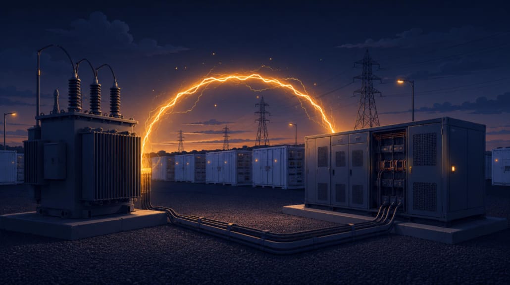
PCS Overvoltage Protection: Coordinating Transformer and Inverter Defense Against High-Voltage Grid Faults
Key Takeaway
PCS overvoltage protection is the layered set of defenses that keeps power conversion systems and transformers online, and undamaged, when grid voltage swells past normal limits. It combines fast surge arresters, DC-bus crowbar circuits, software ride-through control, and coordinated relay settings into one system. So it does not treat the transformer and the inverter as separate problems.
In short, it lines up transformer insulation limits with inverter chip limits. When a high-voltage grid fault hits, ride-through control briefly adjusts reactive current. At the same time, surge arresters and firmware limits shield the delicate IGBT or SiC switches from damaging voltage spikes.
Modern grid codes such as IEEE 1547-2018 require both to stay connected through many of these events. As a result, protection has to work in layers. It also has to be planned jointly. Get the coordination wrong, and the surge arrester clamps too late. Or, just as often, the PCS rides through longer than the transformer’s insulation can bear.
| Quick Answer PCS overvoltage protection combines transformer-side relays (ANSI 59, ANSI 24), surge arresters, and differential protection (ANSI 87T) with PCS-side defenses (DC-bus crowbar circuits, ride-through control, gate-driver clamps). The two systems must be coordinated. Specifically, the arrester should clamp below the PCS trip threshold. Also, the ride-through duration should stay inside the transformer’s short-time withstand rating, per IEEE C57.12. |
Why PCS Overvoltage Protection Differs From Overcurrent Protection
Most protection engineers think in terms of overcurrent first. So fuses, breakers, and relays are usually sized to clear a fault before wires or windings overheat. Voltage swells flip that logic around. Here, the equipment is not drawing too much current. Instead, it is facing too much voltage. So the failure paths are different:
- Load rejection — a large downstream load trips offline, and voltage spikes upstream before regulation catches up
- Single-line-to-ground faults on ungrounded or high-impedance grounded systems, which can push healthy phases toward line-to-line voltage
- Switching transients from capacitor bank energization, transformer tap changes, or line reclosing
- Ferroresonance, more common on lightly loaded systems with long cable runs
Overall, the transformer and the PCS each feel this stress in their own way. That is why PCS overvoltage protection needs two coordinated strategies, not one shared setting. For reference, full ride-through requirements sit inside IEEE 1547-2018, the standard most U.S. interconnection agreements now reference.
Transformer-Side Defenses That Support PCS Overvoltage Protection
Insulation and Core Stress From Sustained Overvoltage
Sustained overvoltage raises the transformer’s flux density. This pushes the core toward saturation. As a result, a saturating core draws jagged, inrush-like current. It also creates hot spots in the windings. Over time, the added vibration and noise speed up insulation aging.
In short, the standard protection layers are:
- ANSI 59 (overvoltage relay) — inverse-time or definite-time curves set to match the interconnection standard’s HVRT voltage-duration envelope
- ANSI 24 (volts/hertz protection) — catches overexcitation specifically. A plain overvoltage relay does not track the frequency side of core saturation. So this is a separate layer, not a substitute
- Surge arresters (gapped silicon-carbide or MOV-based) on both HV and LV terminals, sized to the transformer’s Basic Insulation Level (BIL)
Dielectric Stress From Fast Transients
Switching surges hit inter-turn winding insulation on a fast timescale. Relays cannot catch it. Specifically, that timescale runs sub-millisecond. Protective relaying, by contrast, works over cycles to seconds. So surge arresters and terminal snubber circuits carry the real burden here. By the time an ANSI 59 or 24 element reacts, the fast transient is already gone.
Differential and Overcurrent Protection (ANSI 87T, 50/51)
Alongside overvoltage-specific relaying, transformer protection schemes standardly add two more layers.
Differential protection (ANSI 87T) compares current entering the HV side against current leaving the LV side. It uses Kirchhoff’s Current Law to do this. A mismatch past a set threshold signals an internal winding fault. It trips the breaker within roughly 30 ms. However, inrush and magnetizing current during energization or overvoltage can also create a differential current. So modern relays use harmonic restraint. This tells real faults apart from these normal transients.
Overcurrent and earth fault protection (ANSI 50/51) clears sustained high fault current from grid-side short circuits. It uses instantaneous (50) and inverse-time (51) elements. These typically sit behind the differential scheme. Instead, they act as backup protection, not the first line of defense. Engineers also selectively coordinate the trip settings, so the device closest to a fault clears it first and leaves the rest of the system energized.
Voltage Regulation via On-Load Tap Changers (OLTC)
A BESS often connects to a weak or highly variable grid. There, an on-load tap changer adjusts the transformer’s turns ratio while it stays in service. This holds secondary-side voltage within range without shutting the unit down. So OLTCs offer a slower, mechanical form of voltage regulation. They help absorb sustained voltage drift from renewable generation. But they cannot replace surge arresters or relay protection against fault-driven transients.
Grounding and Shielding
- Low-impedance grounding grid — the transformer enclosure, surge arresters, and PCS frame should bond to the same grounding network. This limits ground potential rise during a fault. It also keeps protective devices on a common reference.
- Electrostatic shielding — an interwinding shield between primary and secondary cuts high-frequency noise and voltage-spike coupling from the grid side into the PCS side. It works alongside surge arrester protection, not in place of it.
PCS Overvoltage Protection: Inverter-Side Defenses
The inverter’s semiconductor switches, whether IGBT or SiC, face DC-bus overvoltage that flows back from an AC-side voltage swell. That exposure gets worse during unbalanced faults. There, the control loop’s own feedback signal becomes thrown off.
DC-Bus Overvoltage Protection
Braking choppers or crowbar circuits dump excess energy into resistors once bus voltage crosses a threshold. This protects the DC-link capacitors and the switches from overvoltage. Usually, it is the first active layer of PCS overvoltage protection to engage during a swell. DC contactors, meanwhile, serve as a hardware failsafe. They isolate the battery racks if the chopper alone cannot keep bus voltage inside a safe window.
AC Overvoltage Ride-Through Control
Older firmware tripped the PCS offline at the first sign of a swell. Modern firmware, built to current interconnection standards, keeps the PCS connected instead. Under IEEE 1547-2018’s default Category III envelope, for example, the PCS must ride through up to 1.10 per-unit for 2 seconds. Between 1.10 and 1.20 per-unit, it can briefly cease energizing instead of disconnecting outright. Above 1.20 per-unit, a full trip is required.
Also, the PCS actively absorbs reactive power, or VARs, to help pull grid voltage back down. As a result, the PCS becomes part of the fix, not just a bystander that disconnects. The LVRT and HVRT ride-through curves that govern this behavior work the same way in both directions. They are just mirrored for sags versus swells.
Volt-VAR and Volt-Watt Curve Control
Ride-through handles transient swells. But IEEE 1547-2018 also standardizes a separate, ongoing grid-support function for milder, sustained overvoltage. When a utility activates it, the PCS runs a volt-VAR curve. Below 1.02 per-unit voltage, the curve sits in a dead zone, and the PCS adds no reactive power. Above that, it starts absorbing reactive power, reaching its full absorption limit at 1.08 per-unit. These are the default curve settings described in a recent IEEE-affiliated study.
Some interconnection agreements also activate volt-watt control. This trims active power output if voltage stays high despite the reactive response alone. It works alongside volt-VAR, not in place of it.
Negative-Sequence Current Limiting
Unbalanced high-voltage faults produce negative-sequence currents. These heat phase legs unevenly. So control loops need an explicit limit here, separate from the general overcurrent limit. Otherwise, a single-phase-biased fault could overheat one leg while the others stay fine.
Fast Semiconductor-Level PCS Overvoltage Protection
Gate-driver desaturation detection and hardware-level overvoltage clamps work in microseconds. They act independently of the software control loop, and faster than it. As a result, they serve as the last line of defense when everything upstream fails to act in time.
Anti-Islanding and Ride-Through Coordination
A high-voltage fault can sometimes cascade into a full outage. When that happens, the PCS must detect that it is energizing a dead section of grid, then disconnect. IEEE 1547-2018 requires this within 2 seconds of island formation. Detection methods split into two types. Passive methods watch for abnormal voltage, frequency, or phase jumps. Active methods, instead, inject a small perturbation, such as a frequency drift, to force a detectable response if the grid is truly gone.
There is a real design tension here. Specifically, a 2019 NREL laboratory study found that ride-through behavior can noticeably slow islanding detection. Even so, run-on times stayed inside the 2-second IEEE 1547-2018 window in every case tested. That happens because a PCS holding voltage and frequency steady during a disturbance can look like a healthy grid connection. For this reason, ride-through and anti-islanding logic need coordinated tuning. They should not run as independent settings. For the full technical report behind this finding, see the Sandia National Laboratories study on OSTI.
Active Voltage Conditioning
Some sites see voltage that never settles, beyond what ride-through settings alone can absorb. For these sites, dedicated power-electronic conditioners sit in-line ahead of the main PCS. One example is ABB’s PCS100 AVC-40, rated from 225 kVA to 3,600 kVA with efficiency above 98 percent.
These units fix sags and swells within milliseconds. Even so, this is an extra device for grids that are weak or noisy all the time. It cannot replace the PCS’s own ride-through and protection functions.
Comparison: Transformer vs. PCS Overvoltage Protection
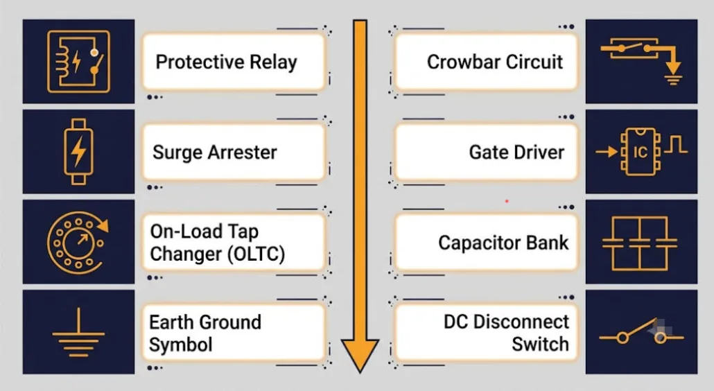
Overall, the table below lines up each side’s defenses by timescale. This makes the gaps between them easy to spot at a glance.
| Protection layer | Transformer | PCS |
|---|---|---|
| Primary threat | Core saturation, insulation aging | DC-bus overvoltage, switch stress |
| Slow protection (cycles–seconds) | ANSI 59 / ANSI 24 relays, ANSI 50/51 overcurrent | Software-based AC overvoltage ride-through control |
| Internal fault detection | ANSI 87T differential protection | Negative-sequence current limiting |
| Fast protection (µs–ms) | Surge arresters, terminal snubbers | Gate-driver desaturation, hardware clamps |
| Energy dissipation | Arrester let-through to ground | Braking chopper / crowbar resistors |
| Sustained voltage drift | On-load tap changer (OLTC) | Active voltage conditioning (external, supplementary) |
| Outage/dead-grid response | Coordinated with PCS anti-islanding | Anti-islanding, disconnect within 2s (IEEE 1547-2018) |
| Fault type most sensitive to | Single-line-to-ground on ungrounded systems | Unbalanced faults (negative-sequence) |
| Governing standard | IEEE C57.12 series | IEEE 1547-2018, UL 1741 SB |
Coordinating Transformer and PCS Overvoltage Protection
Treating these as two independent systems is a common design gap. So three coordination checks matter most for site-wide PCS overvoltage protection.
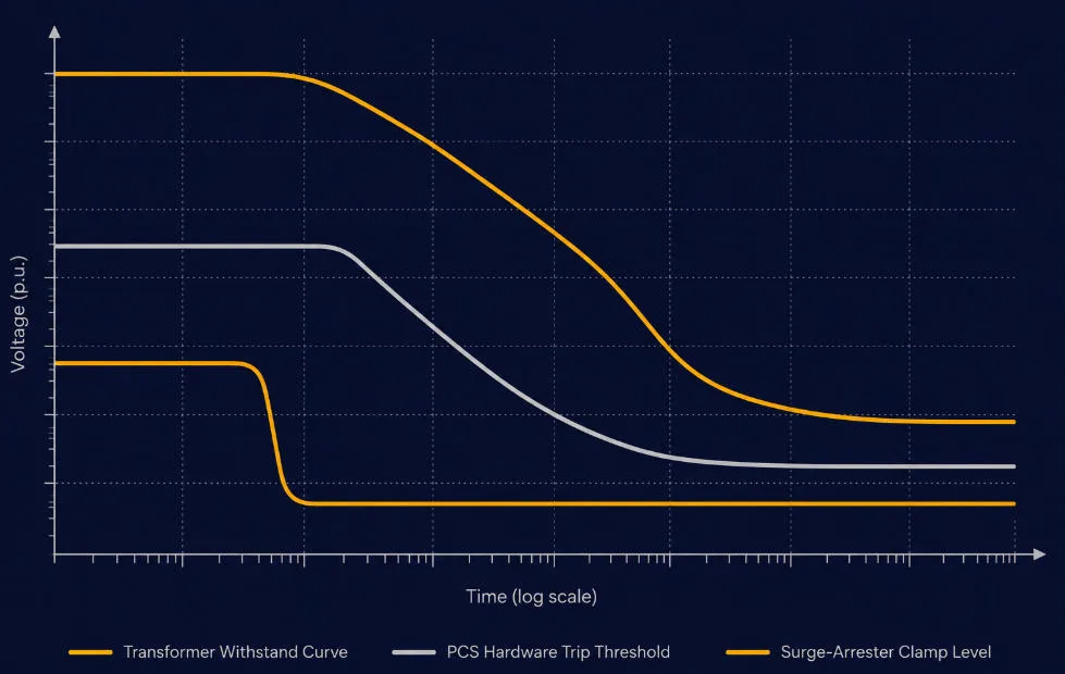
- Let-through voltage vs. PCS trip threshold. The transformer’s surge arrester should clamp transients below the PCS’s hardware overvoltage trip point. This way, the arrester absorbs the transient, not the PCS’s own protection.
- HVRT duration vs. transformer withstand. The voltage-time ride-through curve set in the PCS needs to sit inside the transformer’s short-time overvoltage withstand rating, per IEEE C57.12. Otherwise, the PCS could ride through an event longer than the transformer can structurally take.
- Grounding configuration vs. overvoltage settings. How the system is grounded — solidly grounded, resistance-grounded, or ungrounded — directly sets how much overvoltage a single-line-to-ground fault produces on the healthy phases. This needs joint modeling with the PCS overvoltage settings during system design. It should not be a decision each discipline makes on its own.
- Selective tripping. Transformer relay settings and the PCS’s own protection should be time-graded, so a fault on the PCS side clears at the device closest to it first. Otherwise, a local fault trips more of the system than it needs to.
- Fault current contribution vs. inverter control mode. The differential (87T) and overcurrent (50/51) settings assume a certain fault current magnitude to detect against. A grid-following PCS contributes only limited fault current during a fault, while a grid-forming PCS contributes significantly more. So these relay settings should be checked against which control mode the PCS actually runs — see our grid-forming vs. grid-following BESS guide for the underlying comparison.
Governing Standards for PCS Overvoltage Protection
- IEEE 1547-2018 — interconnection requirements for distributed energy resources, including HVRT voltage-duration curves
- UL 1741 SB — certification testing that verifies HVRT compliance for grid-support equipment
- IEC 61000-4-11 / IEC 61000-4-34 — voltage dip and swell immunity testing for equipment rated below and above 16 A per phase
- IEEE C57.12 series — transformer design and short-time overvoltage withstand standards
For system designers weighing broader grid-support tradeoffs, this same coordination logic also shows up in Fast Frequency Response design. There, too, BESS control settings must stay inside both a grid-code window and the hardware’s own physical limits.
Key Takeaways for PCS Overvoltage Protection Design
| Point | Why It Matters |
|---|---|
| Voltage swells stress equipment differently than overcurrent faults | Insulation and semiconductor limits, not wire heating, drive the failure modes |
| Transformer and PCS need separate, coordinated protection layers | A single shared setting misses the different timescales each device needs |
| Surge arresters and relays cover different timescales | Arresters catch microsecond transients; relays catch cycles-to-seconds events |
| Ride-through duration must stay inside transformer withstand ratings | Otherwise the PCS can hold an overvoltage longer than the transformer can survive |
| Anti-islanding and ride-through logic must be tuned together | Ride-through behavior can otherwise slow dead-grid detection |
FAQ
What’s the Difference Between LVRT and HVRT?
LVRT, or Low Voltage Ride-Through, keeps equipment connected during voltage sags. These are typically caused by faults or heavy load switching. HVRT, or High Voltage Ride-Through, does the same for voltage swells instead. So the control challenges largely mirror each other. But the hardware failure modes differ. Sags stress current limits. Swells stress insulation and semiconductor overvoltage limits instead. For the underlying voltage-duration curves, see our full LVRT and HVRT guide.
Why Does the PCS Absorb Reactive Power During a High-Voltage Fault Instead of Just Disconnecting?
Modern grid codes require ride-through for a clear reason. Mass disconnection of distributed generation during a voltage event can worsen grid instability. So absorbing VARs actively helps pull the voltage back toward normal. As a result, the PCS becomes part of the grid’s self-correction, not a source of added disturbance. For more on how this reactive-power capability is sized and rated, see our BESS power factor guide.
Can a Surge Arrester Alone Provide PCS Overvoltage Protection?
No. Arresters handle fast transients, such as switching surges and lightning-induced events. They work on a timescale of microseconds to milliseconds. Sustained overvoltage from load rejection or a ground fault lasts cycles to seconds instead. That needs the PCS’s own ride-through control. Where ride-through limits run out, it also needs overvoltage relay protection. In short, the two protection types are not interchangeable.
Does Ride-Through Conflict With Anti-Islanding Requirements?
They can pull against each other. Anti-islanding must detect a dead grid and disconnect within 2 seconds under IEEE 1547-2018. Ride-through, meanwhile, is built to keep the PCS connected through a disturbance rather than tripping. A 2019 NREL study found ride-through can slow islanding detection. That happens because a PCS holding voltage and frequency steady during the event looks like a stable grid connection. For this reason, both functions need tuning together at commissioning. Neither should be set on its own.
Why Must PCS Overvoltage Protection Settings Match the Transformer’s Withstand Rating?
Say the PCS’s HVRT setting runs longer than the transformer can withstand. The PCS still stays connected and rides through the event as designed. But the transformer can suffer accelerated insulation aging. In a severe enough event, it can suffer immediate insulation failure instead. That happens because it sits at an overvoltage level longer than its short-time withstand rating allows. This is the core reason the two systems’ settings need coordination at the design stage. They should not be configured apart from each other.
Further Reading
LVRT and HVRT: Voltage Ride-Through for BESS and Solar
Fast Frequency Response (FFR): How BESS Stabilizes Grid Frequency in Milliseconds
BMS Cycle Counting Explained: EFC vs. Rainflow Algorithms
BESS Power Factor Explained: Complete Guide




Trackbacks & Pingbacks
[…] EV charging now shares the same grid-connect framework as solar and battery inverters. See our PCS overvoltage protection guide for how these settings interact with anti-islanding and ride-through […]
[…] PCS Overvoltage Protection: Transformer Coordination says: July 23, 2026 at 1:21 am […]
[…] protect the DC bus from electrical faults. Key protection functions include over-current limiting, overvoltage protection and DC bus voltage regulation, pre-charge control to prevent capacitor inrush, earth fault […]
Leave a Reply
Want to join the discussion?Feel free to contribute!