Microgrid BESS: The Complete Guide to Battery-Powered Microgrids
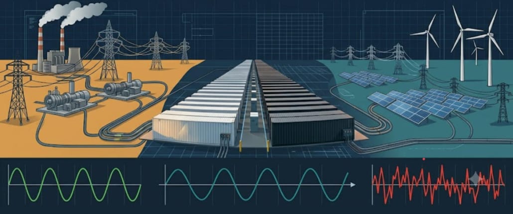
Power outages cost businesses billions every year. Aging grid infrastructure, extreme weather, and the variable nature of solar and wind energy make centralized power systems less reliable. As a result, energy-forward organizations are turning to microgrid BESS — a combination of distributed energy resources and battery storage that can supply power independently of the utility grid.
A microgrid BESS is not simply a backup generator. Instead, it is an intelligent energy platform that stores renewable energy, dispatches it on demand, and switches smoothly between grid-connected and islanded operation. To understand the foundation of this technology, read our ultimate guide to battery energy storage systems before diving into the microgrid-specific details covered here.
This guide covers everything EPCs, project developers, and commercial energy buyers need to know. Topics include: how these systems work, core components, sizing methodology, use cases, grid-forming technology, relevant standards, and financial considerations.
What Is a Microgrid BESS?
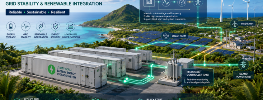
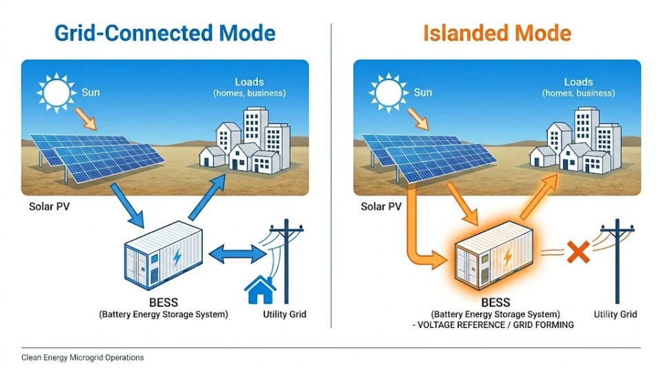
A microgrid is a local energy network. It integrates distributed energy resources — solar PV, wind turbines, diesel generators, and battery storage — into one controllable system. Crucially, it can run in two modes: grid-connected (exchanging power with the utility) or islanded (supplying loads on its own).
Battery storage is the technology that makes islanded operation practical. Without BESS, a microgrid relying on solar cannot guarantee stable voltage and frequency when it disconnects from the grid. With BESS, however, the system buffers generation gaps, sustains loads overnight, and holds the frequency reference that other devices need. For a broader look at how BESS works across sectors, see our guide on top applications of commercial and industrial BESS.
In short: BESS is the backbone of a modern microgrid. It turns a set of distributed generators into a self-sufficient power system.
Grid-Connected vs. Islanded Microgrid BESS
Microgrid BESS operates in two fundamental modes. Understanding both is essential before sizing or specifying a system.
- Grid-connected mode: The microgrid stays synchronized with the utility. BESS handles peak shaving, load shifting, and frequency regulation. Excess solar generation is stored or exported.
- Islanded (off-grid) mode: The microgrid disconnects at the point of common coupling. BESS then acts as the voltage reference, sustaining all local loads entirely on its own.
Seamless transition between these modes is a critical performance target. Research published in Energies (2026) showed loss-of-mains detection in under 3 milliseconds — well within the 10-millisecond threshold needed for sensitive equipment to ride through without disruption.
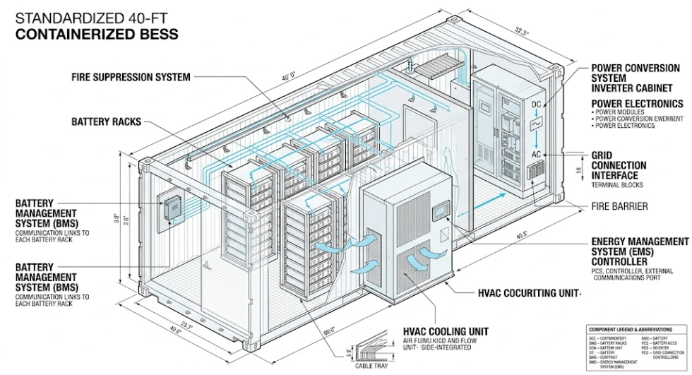
Core Components of a Microgrid BESS System
A complete microgrid BESS integrates several interdependent subsystems. Knowing each one helps EPCs design reliable systems and helps project developers evaluate vendor proposals accurately.
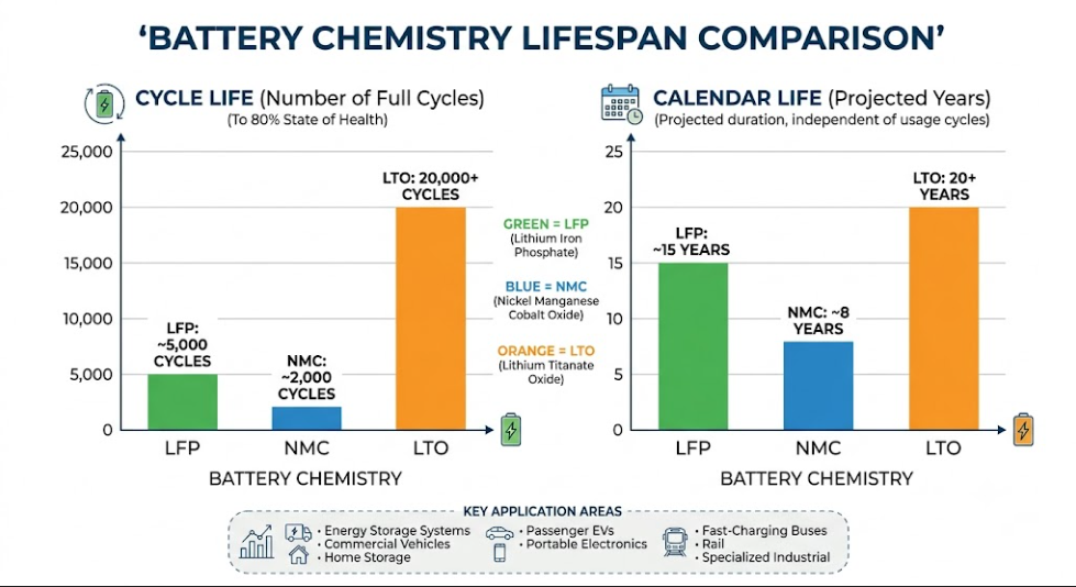
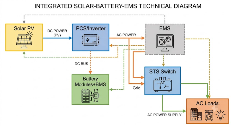
1. Battery Modules and Racks — LFP Chemistry
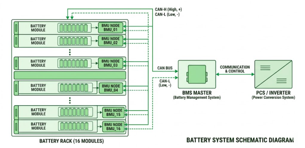
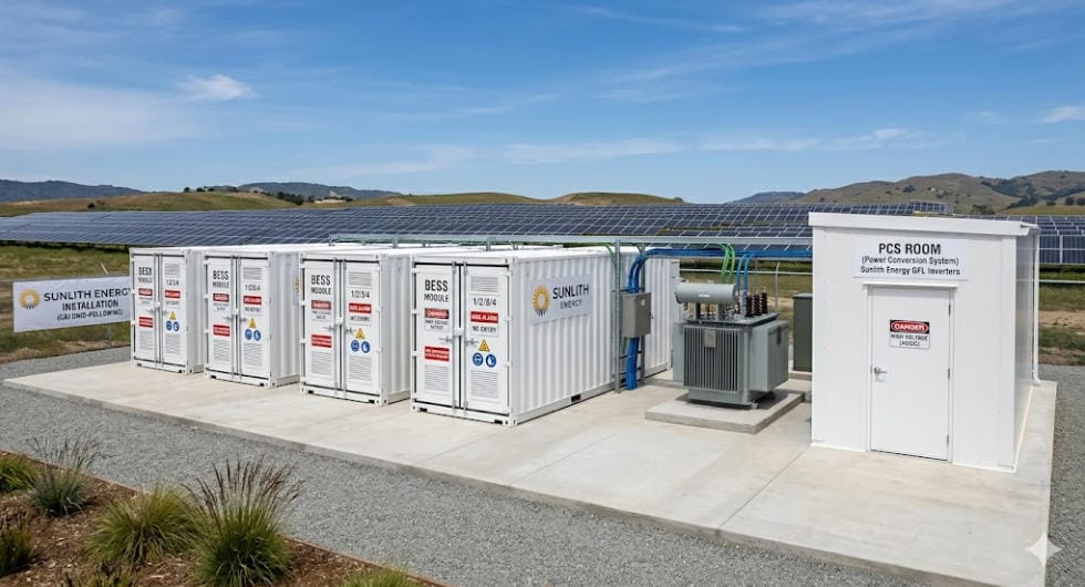
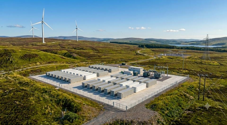
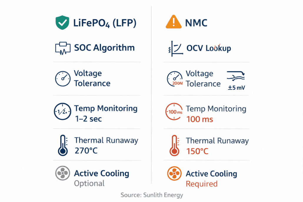
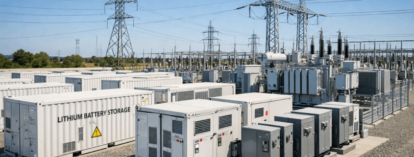
Lithium Iron Phosphate (LFP) chemistry dominates microgrid deployments today. LFP delivers over 6,000 cycles at 80% depth of discharge. It also operates safely across wide temperature ranges and avoids the thermal runaway risk seen in NMC chemistry. Battery modules are assembled into racks and housed in containerized enclosures for rapid site deployment.
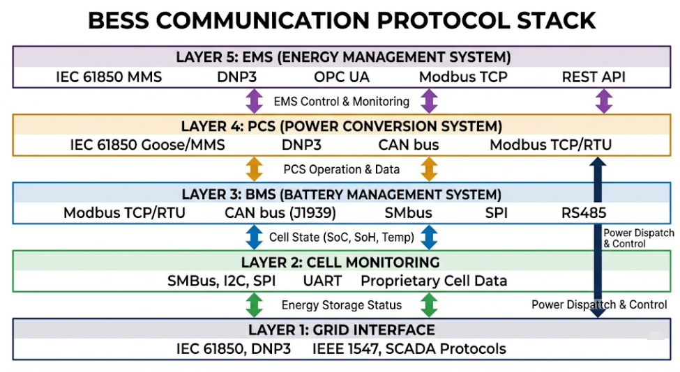
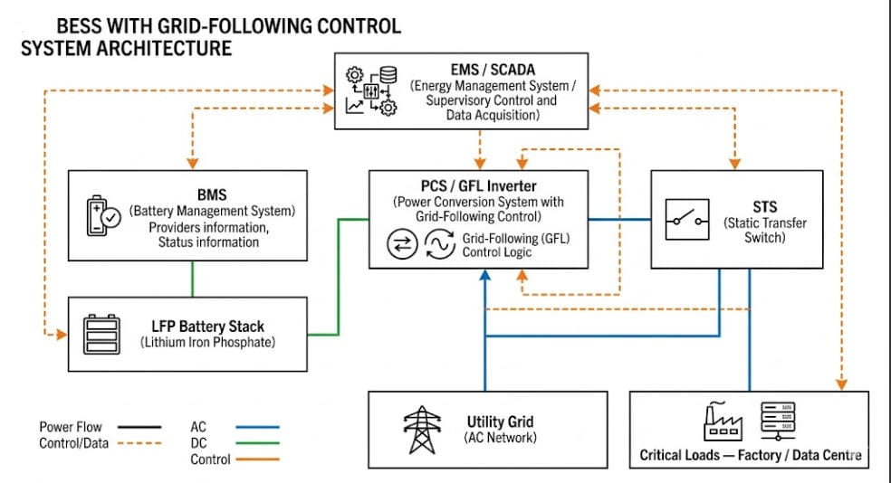
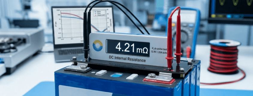
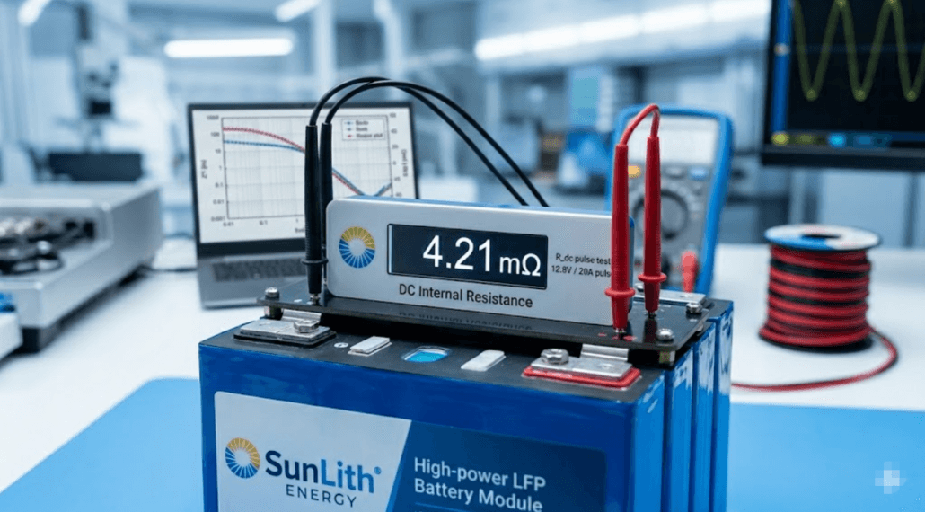
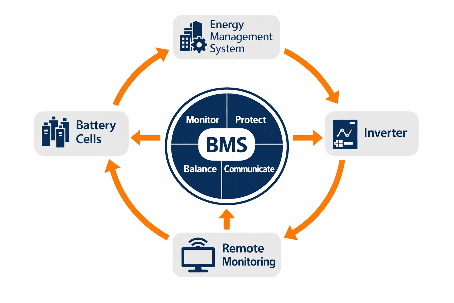
2. Battery Management System (BMS)
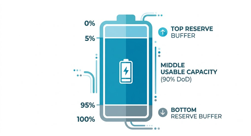
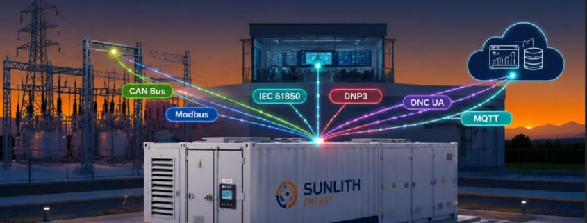
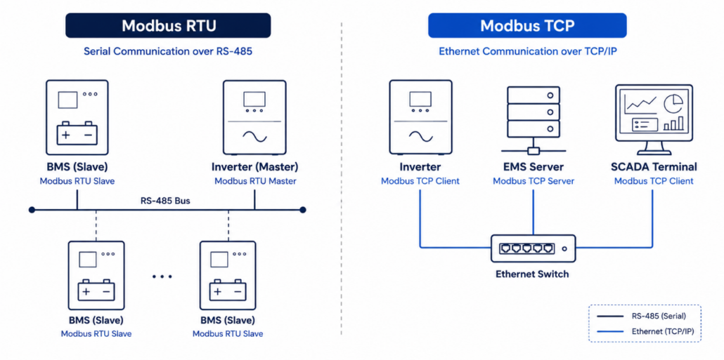
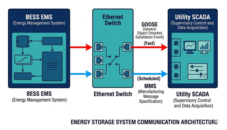
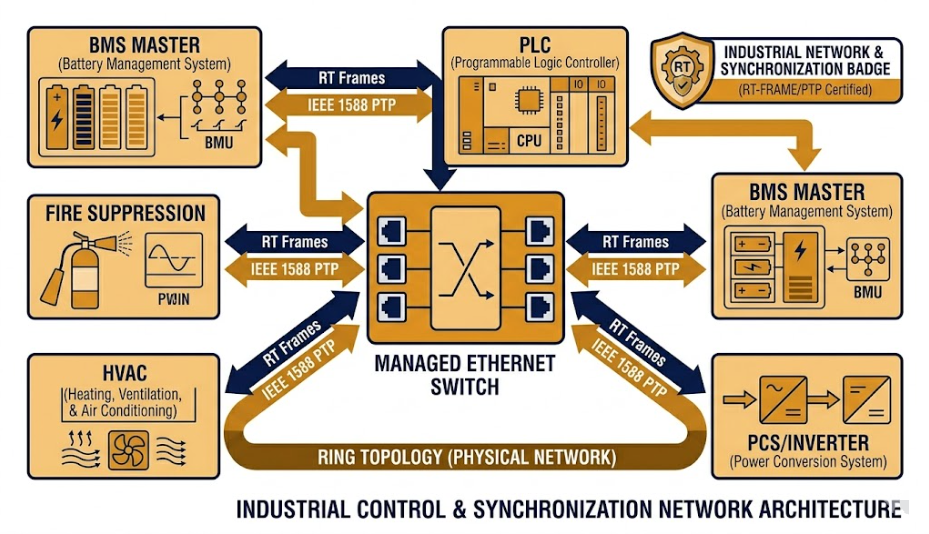
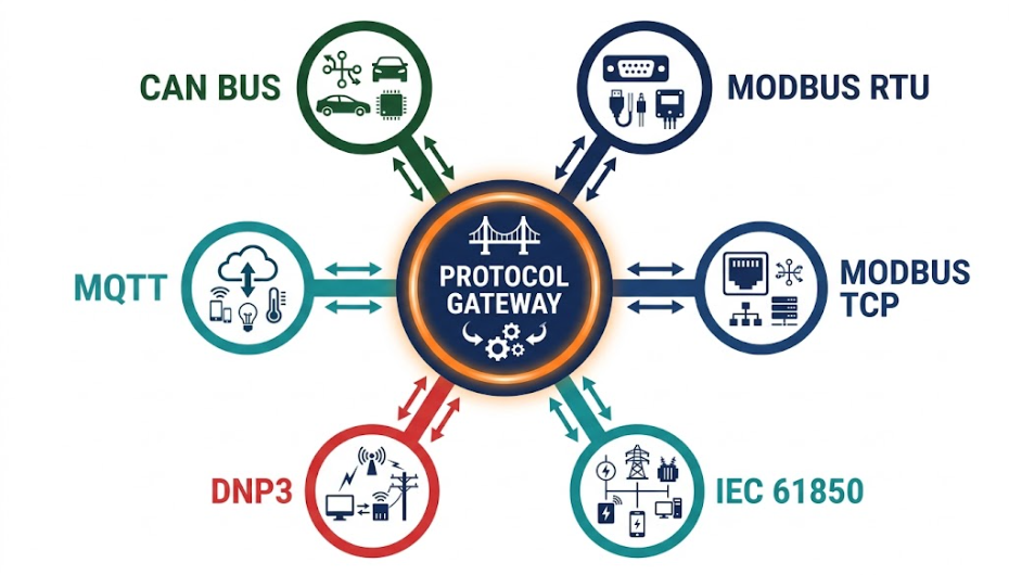
The BMS monitors cell-level voltage, temperature, and current. It enforces SoC limits (typically 20–80% under the 20/80 cycling rule), calculates State of Health (SoH), and tracks DC Internal Resistance (DCIR). Additionally, the BMS communicates with the EMS via CAN bus or Modbus. For a deeper look at how the EMS works inside a BESS, we have a dedicated technical article on the subject.
3. Power Conversion System (PCS)
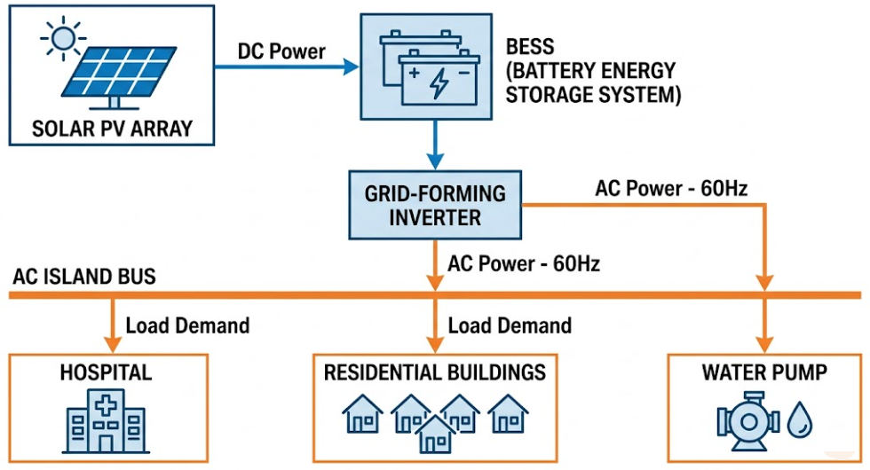
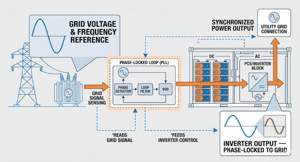
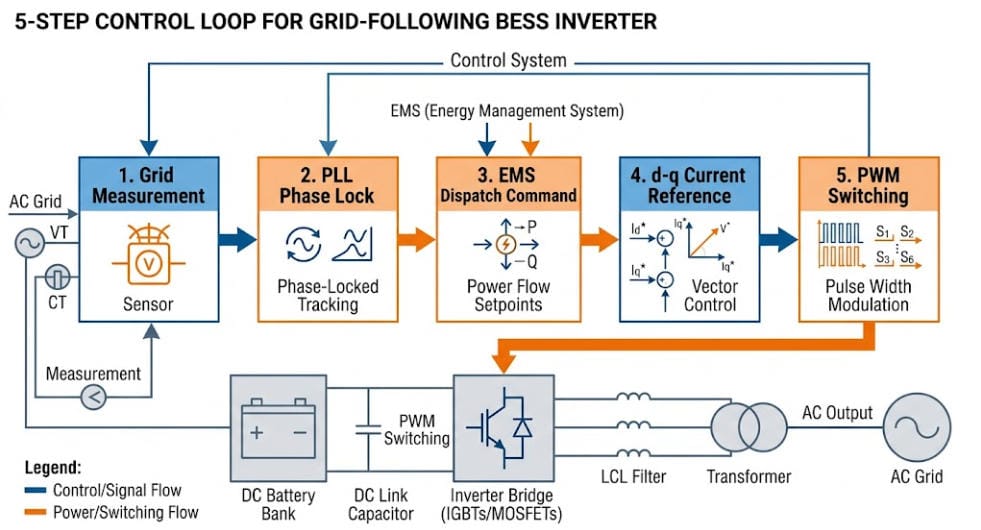
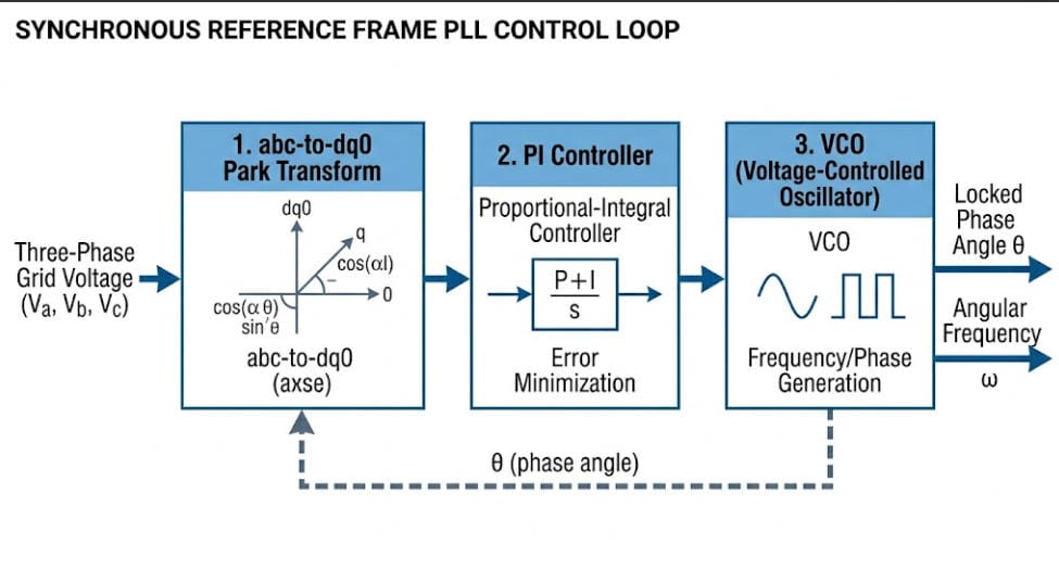
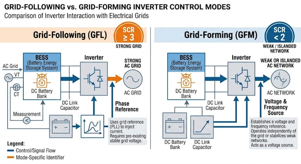
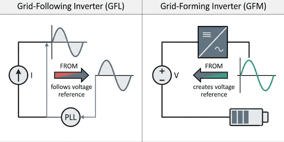
The PCS — also called the bidirectional inverter — converts DC energy from batteries into AC power for loads. It also converts AC to DC during charging. In a microgrid, the PCS can operate in grid-following or grid-forming mode. Grid-forming units synthesize voltage and frequency from scratch, which makes islanded operation possible even without a utility reference.
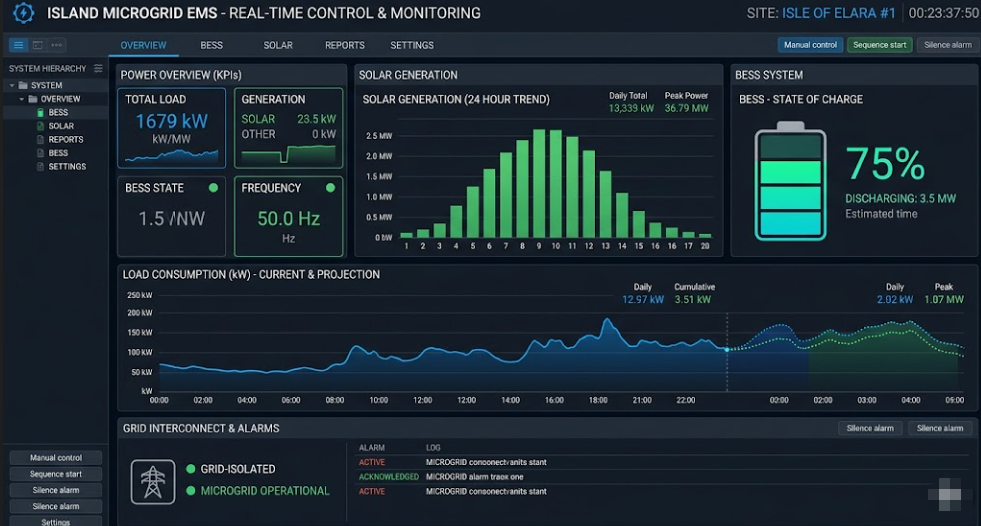
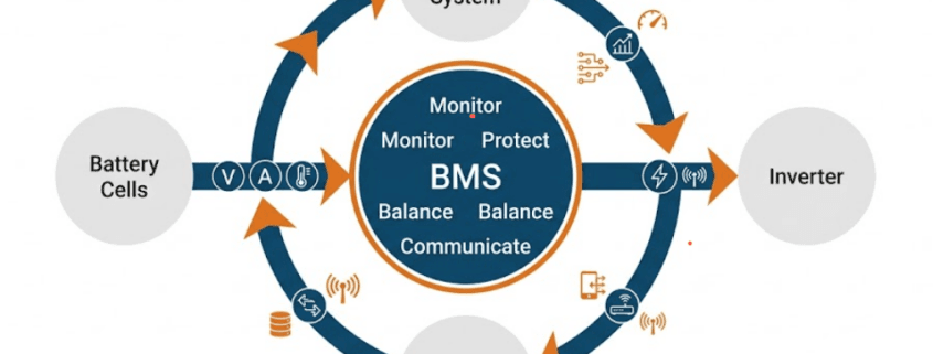
4. Energy Management System (EMS)
The EMS is the intelligence layer. It receives data from the BMS, PCS, solar inverters, load meters, and weather forecasts. Then it dispatches charge/discharge commands to optimize across multiple objectives simultaneously — peak shaving, renewable self-consumption, SoC management, and grid services. Moreover, it governs mode transitions and coordinates load shedding during generation shortfalls. Read our full breakdown of how EMS enables advanced grid services through BESS to see exactly how this works in practice.
5. Solar PV Array
Solar PV is the primary generation source in most microgrid BESS deployments. The PV array charges the BESS during daylight hours. As a result, the BESS can supply loads through the night or during cloud cover. Oversizing the PV-to-BESS ratio — typically 1.2× to 1.5× — ensures adequate charging under real-world irradiance conditions.
6. Point of Common Coupling (PCC) Switch / STS
The PCC switch or Static Transfer Switch (STS) is the electrical boundary between the microgrid and the utility grid. During a grid disturbance, the STS opens within milliseconds to island the microgrid. When grid power returns and stabilizes, the STS synchronizes and re-closes. Consequently, the speed and reliability of this device directly determines the quality of power continuity during transitions.
Microgrid BESS Component Summary Table
| Component | Primary Function | Key Standard | Typical Technology |
| Battery Module | Store DC energy | IEC 62619, UL 1973 | LFP, NMC |
| BMS | Cell monitoring, protection, SoH tracking | IEC 62133-2 | Rack-level + pack-level |
| PCS / Inverter | DC↔AC conversion, grid forming/following | IEEE 1547, UL 1741 | Grid-forming (VSM/droop) |
| EMS | Dispatch, optimization, mode transitions | IEC 62933-5-2 | SCADA + AI forecasting |
| STS / PCC Switch | Grid isolation, mode transition | IEEE 1547.4 | <20 ms transfer |
| Solar PV Array | Primary renewable generation | IEC 61215, IEC 61730 | Monocrystalline TOPCon |
| Thermal Management | Temperature control, fire suppression | NFPA 855, UL 9540A | HVAC + liquid cooling |
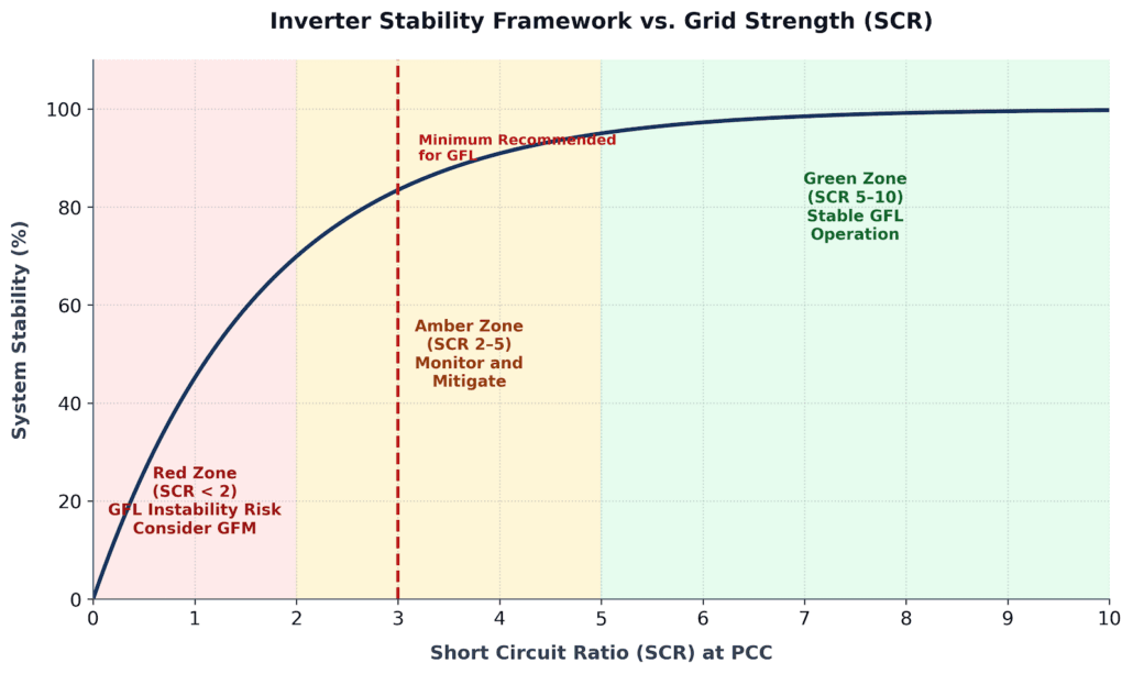
Grid-Forming BESS: The Key to True Islanding
The most important technology choice in any microgrid BESS project is the inverter control mode. Specifically, you must decide between grid-following and grid-forming. This single decision determines whether the system can operate independently of the utility at all. Our detailed grid-forming vs. grid-following BESS guide covers the full technical comparison, but the key points are summarized below.
Grid-Following BESS: Its Core Limitation
A grid-following inverter acts as a current source. It detects the voltage and frequency of an active grid and synchronizes its output to that reference. Therefore, if the grid disappears — during a blackout — a grid-following inverter cannot sustain islanded operation. It must shut down immediately per IEEE 1547 anti-islanding requirements to protect utility workers.
This means a grid-following BESS cannot black-start a dead network. Nor can it sustain an islanded microgrid on its own. As a result, it is not a viable standalone solution for resilience-critical sites.
Grid-Forming BESS: How It Creates the Grid
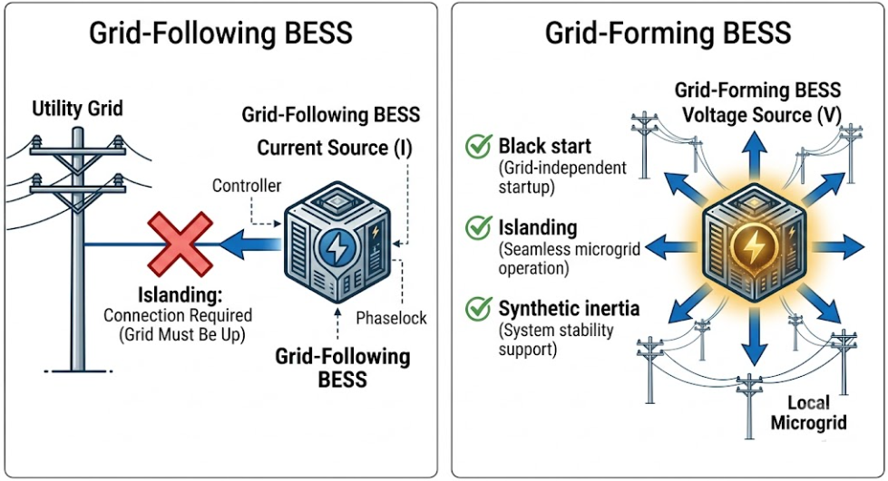
A grid-forming inverter operates as a voltage source instead. Rather than following an external signal, it synthesizes its own voltage waveform and frequency using algorithms such as Virtual Synchronous Machine (VSM) or droop control. Consequently, all devices on the microgrid — other inverters, loads, generators — synchronize to the grid-forming BESS.
This fundamental shift in control architecture unlocks four critical capabilities:
- Black start: The grid-forming BESS energizes a completely dead network from zero.
- Sustained islanding: The microgrid runs indefinitely without any utility connection.
- Synthetic inertia: The inverter emulates the rotational inertia of a synchronous generator, stabilizing frequency during rapid load changes.
- Fault current contribution: The system provides enough fault current to trip protection relays, enabling conventional protection coordination.
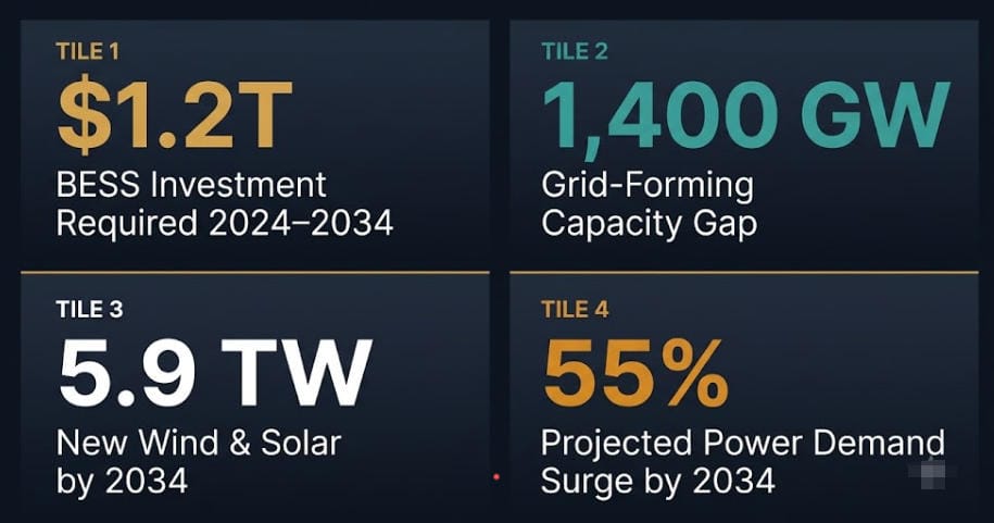
As of mid-2025, Australia had deployed 1,070 MW of grid-forming BESS across ten sites, according to AEMO. Furthermore, a 2025 Nature Scientific Reports study confirmed that integrated grid-forming inverter strategies significantly improve microgrid resilience under fault conditions. This real-world track record proves that grid-forming technology is no longer experimental.
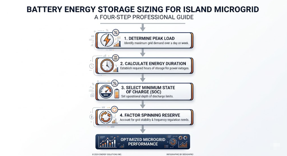
How to Size a Microgrid BESS System
Getting the size right is critical. An undersized system fails to cover loads overnight or during weather events. An oversized system wastes capital. Fortunately, the sizing methodology follows four clear, sequential steps.
Step 1 — Establish the Load Profile
Start with a complete energy audit. Measure peak demand (kW) and daily energy consumption (kWh). Identify critical loads that must run during islanding and non-critical loads that can be shed. Also account for motor start-up inrush currents, which can reach 6× running current and must be covered by the PCS peak power rating.
Step 2 — Define Autonomy Duration
Autonomy duration is the number of hours the microgrid must sustain critical loads without solar generation or grid support. For most commercial microgrids, 4–8 hours covers overnight periods. For resilience-critical facilities such as hospitals or data centers, however, 24–72 hours of autonomy is the standard design target.
Step 3 — Apply the Sizing Formula
Use this baseline formula to calculate required battery capacity:
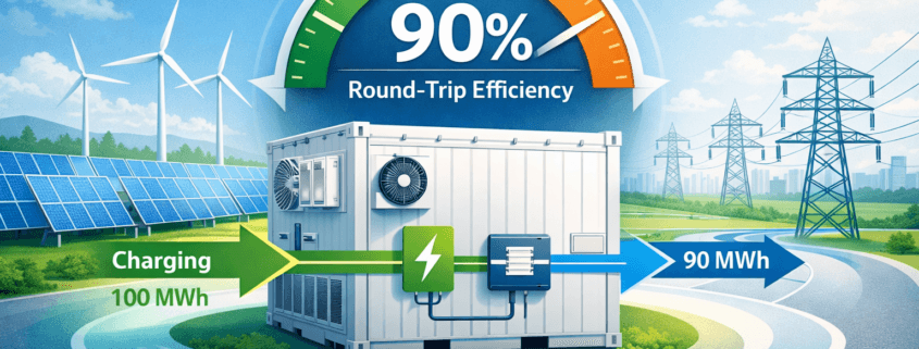
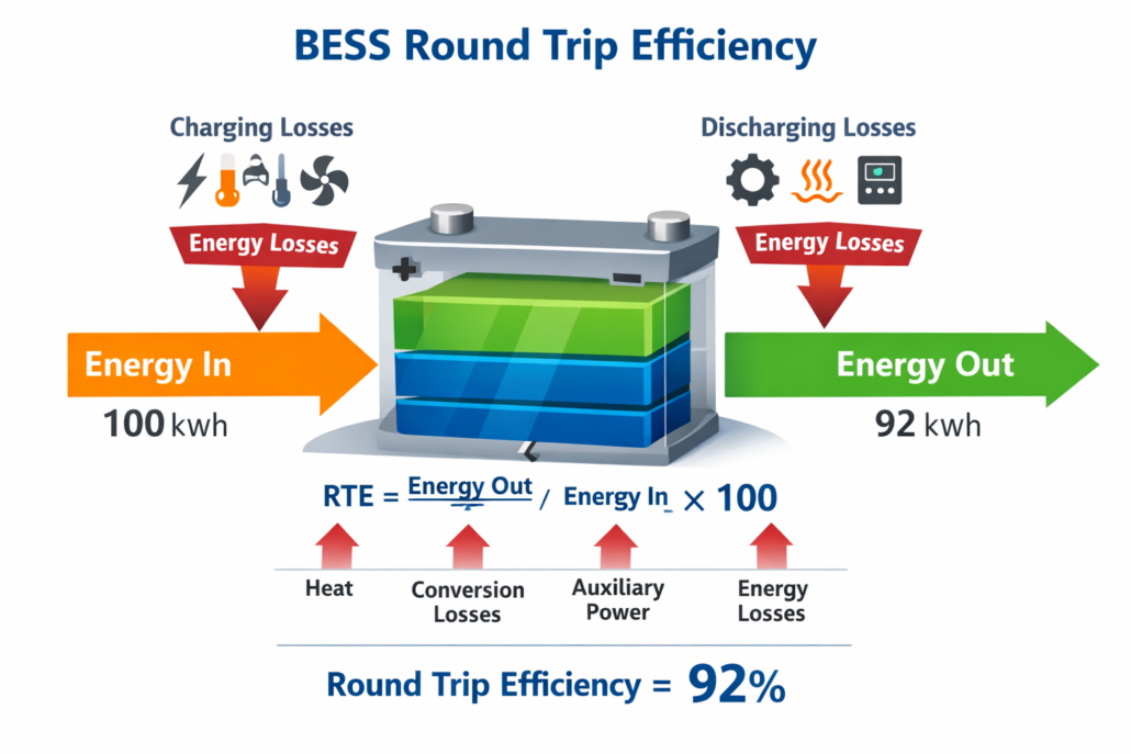
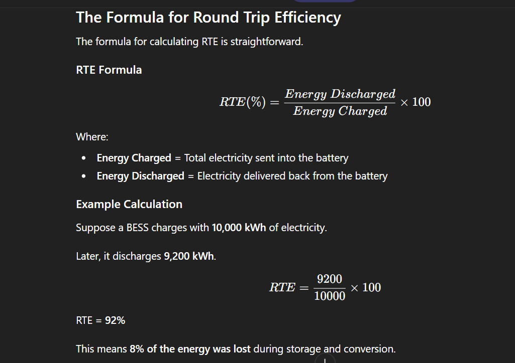
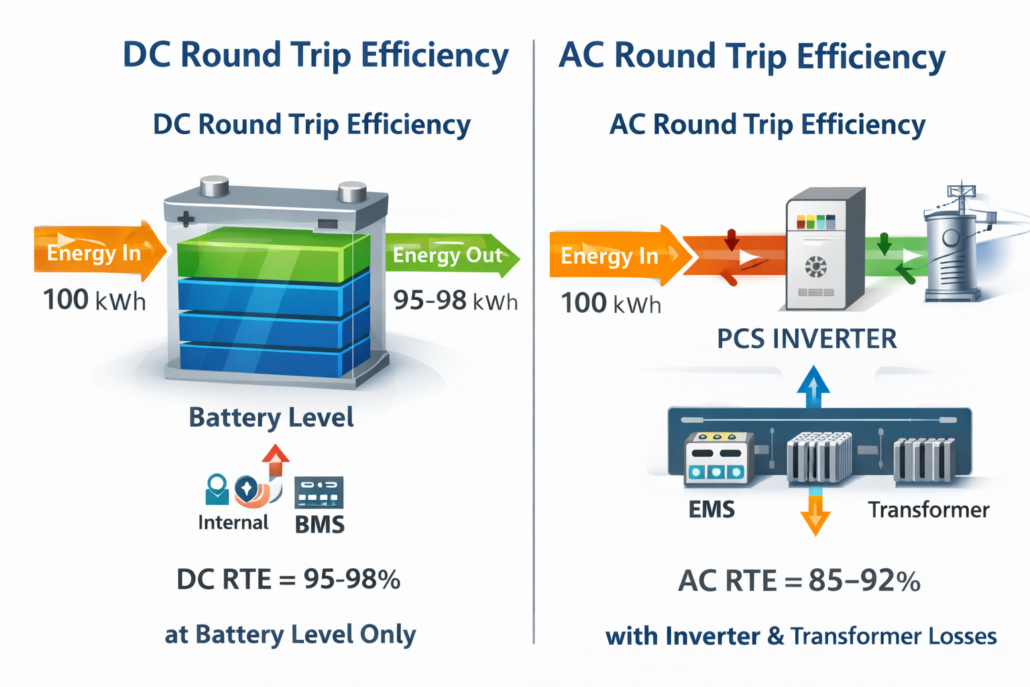
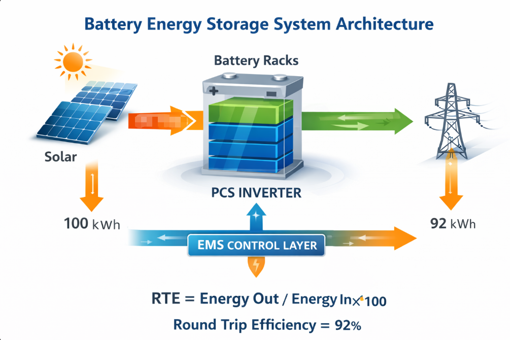
Required BESS Capacity (kWh) = [Critical Load (kW) × Autonomy (h)] ÷ (DoD × RTE)
Here: DoD = usable depth of discharge (0.80 for LFP); RTE = round-trip efficiency (0.92 for modern LFP BESS). Always add a 10–15% spinning reserve margin on top for frequency stability headroom.
Step 4 — Size the Solar PV Array
The solar PV array must fully recharge the BESS within the available daylight window. For a system that recharges overnight-depleted batteries within 6–8 hours of sunlight, a PV-to-BESS ratio of 1.3× to 1.5× is typically required. NREL’s battery storage FAQs provide reliable guidance on irradiance-based sizing methodology that you can apply directly to project scoping.
Microgrid BESS Sizing Reference Table
The table below assumes LFP chemistry, 80% DoD, 92% RTE, 10% spinning reserve, and 12-hour overnight autonomy:
| Application | Critical Load (kW) | Autonomy (h) | BESS Size (kWh) | Solar PV (kWp) |
| Remote Village | 50 | 12 | 817 | 1,060 |
| Commercial Campus | 250 | 8 | 2,717 | 3,500 |
| Hospital / Critical Site | 500 | 24 | 16,304 | 21,000 |
| Mining / Industrial | 1,000 | 12 | 16,304 | 21,000 |
| Island Community | 2,000 | 12 | 32,609 | 42,000 |
Note: These are scoping figures only. Final sizing must account for site-specific irradiance, load diversity factor, planned expansion, and local grid code requirements.
Microgrid BESS Use Cases: Six Key Applications
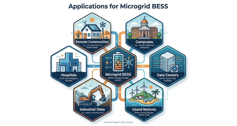
Microgrid BESS is no longer a niche solution for remote communities. It is now essential infrastructure across a wide range of sectors. Here are the six leading applications driving global deployment today.
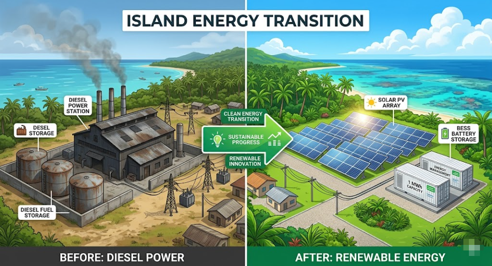
1. Remote and Off-Grid Communities
Approximately 770 million people still lack reliable electricity access. Many live in locations where grid extension is economically unviable. Solar-plus-BESS microgrids offer a proven alternative to diesel generation. According to IRENA’s renewable energy statistics, the levelized cost of energy from a solar-battery islanded microgrid has fallen below $0.18/kWh in high-solar-resource locations — competitive with or cheaper than diesel, even before accounting for fuel logistics costs.
2. Hospitals and Healthcare Facilities
Power interruptions in healthcare settings can have life-threatening consequences. Research published in Energy and Buildings (2025) modelled a solar-BESS microgrid for a hospital on Lombok Island. A correctly sized system supplying 7 MWh per day maintained 100% reliability across a simulated 3-day grid outage with zero diesel required. Therefore, microgrid BESS in healthcare is not just an economic choice — it is a life-safety infrastructure decision.
3. Mining and Industrial Sites
Mining operations in remote locations have historically relied on diesel generators. Diesel logistics add cost and operational risk. A documented case study from our island grid BESS resource collection shows a mining site that replaced three diesel gensets with a solar-plus-BESS microgrid using VSG grid-forming control. In year one, diesel fell by 78%. By year two, after a solar expansion, diesel was phased out entirely.
4. Commercial Campuses and Universities
Large campuses with significant on-site renewable generation are strong microgrid BESS candidates. These systems reduce utility demand charges through peak shaving. They also enable grid services revenue through frequency regulation markets. Moreover, they provide resilience against utility outages. Our overview of grid-scale BESS deployments covers how campus-scale and utility-scale systems create stacked value from a single BESS asset.
5. Data Centers and Digital Infrastructure
AI infrastructure expansion is driving unprecedented data center power demand. Many operators are deploying microgrid BESS as a dual-purpose solution: resilience insurance against grid outages and a cost-optimization tool to reduce peak demand charges. Systems rated 1 MW to 5 MW captured 42.7% of microgrid project activity in 2025, aligning closely with hospital campus, university, and data center scale requirements.
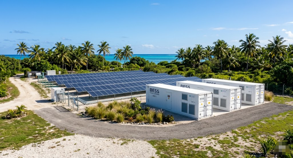
6. Island Nations and Coastal Communities
Island nations face unique energy challenges. They depend entirely on expensive imported diesel, which is vulnerable to supply chain disruption. Pacific Island countries including Fiji, Vanuatu, and Samoa are targeting 100% renewable electricity by 2030. Solar-storage microgrids are the primary technology vehicle for reaching that goal. As a result, microgrid BESS has become a sovereign energy security tool for these nations, not just a technical option.
Microgrid BESS Standards and Certifications
Compliance with the right standards is mandatory for grid interconnection, insurance approval, and project financing. The DOE BESSIE supply chain report (2024) provides a comprehensive overview of applicable standards across all BESS system layers. The core standards governing microgrid BESS are listed below.
- IEEE 1547 / IEEE 1547.4: Interconnection requirements, islanding protection, and re-synchronization for DERs.
- IEEE 2030.2: Interoperability guide for energy storage systems with electric power infrastructure.
- IEC 62933-5-2: Safety requirements for grid-integrated energy storage systems.
- IEC 62619: Safety requirements for lithium cells and batteries in stationary applications.
- UL 1973: Batteries for stationary and light electric rail applications.
- UL 9540: Energy storage systems and equipment.
- UL 9540A: Test method for thermal runaway fire propagation in BESS.
- NFPA 855: Installation standard for stationary energy storage systems (fire safety).
For grid-connected microgrid BESS in North America, IEEE 1547 is the foundational requirement. It governs voltage ride-through, frequency response, anti-islanding, and re-closing behavior. Projects exporting to utility grids also require interconnection studies including short-circuit analysis and protection coordination.
Microgrid BESS Market: Growth and Outlook
The global microgrid market is growing rapidly. According to MarketsandMarkets, the market will reach USD 95.16 billion by 2030, up from USD 43.47 billion in 2025 — a CAGR of 17.0%. This growth reflects a decisive shift toward localized, resilient, and low-carbon energy systems worldwide.
Several structural forces are driving this expansion:
- Falling battery costs: LFP battery pack prices have fallen more than 80% over the past decade. As a result, solar-plus-BESS microgrids now compete economically with grid power in many markets.
- Grid resilience mandates: California’s SGIP program catalyzed more than 1,200 MW of community microgrids by early 2026. Furthermore, the U.S. Department of Defense has mandated microgrid deployments at all major domestic installations by 2030.
- AI and data center demand: The proliferation of AI infrastructure is driving record data center power consumption, which in turn accelerates microgrid BESS adoption in this sector.
- Island and remote electrification: National governments in Pacific Island countries and Sub-Saharan Africa are deploying solar-BESS microgrids as the primary path to 100% renewable electricity targets.
Asia-Pacific is the fastest-growing region, with a projected CAGR of 23.7% — driven by rural electrification programs and industrial decarbonization across Southeast Asia. North America, meanwhile, retains the largest market share at approximately 38.6%.
Financial Considerations: LCOS, CAPEX, and Revenue
Levelized Cost of Storage (LCOS)
LCOS is the primary metric for evaluating a microgrid BESS investment. It represents total ownership cost — capital, installation, operations, and financing — divided by total energy dispatched over the system’s lifetime. For LFP BESS with 6,000+ cycle life, LCOS has fallen dramatically in recent years. In high-solar-resource locations with favorable financing, solar-plus-BESS microgrid LCOS is now below $0.18/kWh, which is competitive with retail grid tariffs in many markets.
Indicative CAPEX Range
All-in CAPEX for a fully commissioned microgrid BESS — including solar PV, BESS, PCS, EMS, STS, civil works, and grid interconnection — typically ranges from $400–$700/kWh for systems above 1 MWh. Smaller systems carry higher per-kWh costs due to fixed engineering and interconnection expenses. Battery storage costs alone have fallen to $120–$180/kWh at the pack level for utility-scale LFP procurement in 2025.
Multiple Revenue Streams
A well-designed microgrid BESS earns value from several streams at once. This stacking of revenue is one of the key reasons project economics have improved so significantly.
- Demand charge reduction: Peak shaving cuts utility demand charges, which can represent 30–50% of commercial electricity bills.
- Energy arbitrage: Charge during low-tariff periods and discharge during high-tariff periods.
- Grid services: Frequency regulation, fast frequency response (FFR), and spinning reserve markets add additional revenue for grid-connected systems.
- Diesel displacement: For off-grid sites, BESS value is measured in fuel savings. At $1.00–$1.50/liter, diesel displacement provides rapid payback on BESS capital.
- Microgrid-as-a-Service (MaaS): Developers bear upfront capital in exchange for long-term PPAs, eliminating CAPEX for end-users. According to Grand View Research, the global MaaS market was valued at USD 2.87 billion in 2024 and is projected to reach USD 6.56 billion by 2030.
EPC and Developer Project Checklist
For EPCs and project developers evaluating a microgrid BESS deployment, the following checklist covers the critical design and procurement decisions in the correct sequence:
- Conduct a full energy audit — peak demand (kW), daily energy (kWh), and critical vs. non-critical load segregation.
- Define autonomy requirements — hours of backup for critical loads, accounting for expected solar generation gaps.
- Select battery chemistry — LFP for longevity, safety, and cycle life; NMC for applications where energy density is the priority.
- Choose inverter control mode — grid-forming PCS is required for islanding, black start, and renewable penetration above 60–70%.
- Design the PCC switch or STS — specify less than 20 ms transfer time and determine protection coordination.
- Size the solar PV array — target 1.3–1.5× PV-to-BESS ratio and use NREL PVWatts for site-specific yield estimation.
- Specify the EMS — ensure multi-objective optimization across peak shaving, SoC management, renewable self-consumption, and grid services.
- Confirm applicable standards — IEEE 1547, UL 9540, UL 1973, NFPA 855, and any local grid codes.
- Conduct an interconnection study — short-circuit analysis, protection coordination, and harmonic assessment.
- Evaluate financing structures — direct CAPEX, green bonds, development finance institutions, or a MaaS PPA arrangement.
Conclusion
Microgrid BESS has crossed from specialized niche technology into mainstream energy infrastructure. Falling battery costs, proven grid-forming inverter technology, mature EMS platforms, and well-established compliance standards have collectively removed the barriers that once limited microgrid deployment.
Today, a microgrid BESS can simultaneously reduce energy costs, generate grid services revenue, provide life-safety resilience, displace diesel, and deliver a platform for 100% renewable operation. Moreover, the market is growing at 17% CAGR globally — with Asia-Pacific exceeding 23%. For EPCs and developers, the question is no longer whether microgrid BESS works. The questions are: what size, what chemistry, what inverter architecture, and what financing model best fits your specific project. Read our broader grid-scale BESS guide to see how microgrid BESS fits into larger utility-scale energy storage strategies.

Sunlith Energy provides technical guidance, BESS system supply, and project development support for microgrid BESS projects at commercial and utility scale. Contact our team to discuss your project requirements.