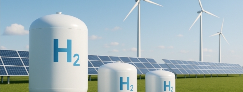
Green hydrogen storage is a hot topic in the clean energy world. As more industries look to hydrogen as a zero-carbon fuel, knowing how to store it safely and efficiently becomes just as important as making it.
In this post, we’ll break down what green hydrogen is, why storage matters, how it’s done, and what challenges we face in storing this promising fuel.
What Is Green Hydrogen?
Before we talk about green hydrogen storage, let’s understand what green hydrogen is. Hydrogen is the most abundant element in the universe. But on Earth, we have to produce it because pure hydrogen gas doesn’t exist naturally.
There are a few main ways to store green hydrogen. Let’s look at the most common ones:
1. Compressed Gas Storage
This is the simplest and most common method today. Hydrogen gas is compressed to high pressures — typically 350–700 bar — and kept in special high-pressure tanks.
Pros:
Mature technology
Relatively low cost for small-to-medium storage
Cons:
Requires strong, heavy tanks
Energy needed for compression
2. Liquid Hydrogen Storage
Hydrogen can be cooled to −253°C to become a liquid. Storing hydrogen as a cryogenic liquid reduces its volume about 800 times compared to its gaseous state.
Pros:
High storage density
Useful for large-scale transport (e.g., shipping)
Cons:
Expensive to chill hydrogen to these temperatures
Boil-off losses due to heat leaks
3. Materials-Based Storage (Solid Storage)
Another method is storing hydrogen in solid materials — like metal hydrides or chemical carriers.
Hydrogen binds with certain metals or chemicals and can be released when needed.
Pros:
High safety level (low pressure)
Compact storage
Cons:
Expensive materials
Slow hydrogen release rates
Where Is Green Hydrogen Storage Used?
Energy Storage: Store excess renewable energy in the form of hydrogen.
Transport: Fuel for hydrogen cars, trucks, buses, and even planes.
Industry: For steelmaking, ammonia production, or backup power.
While the technology is promising, there are still hurdles:
✅ High costs of compression, liquefaction, or materials ✅ Safety concerns (hydrogen is highly flammable and leaks easily) ✅ Lack of storage infrastructure in many places ✅ Energy losses during storage and retrieval
Researchers and companies worldwide are working to make green hydrogen storage safer, cheaper, and more efficient.
The Future of Green Hydrogen Storage
With more investment and innovation, the future looks bright. We may see new storage technologies — like underground hydrogen caverns, advanced metal hydrides, or organic liquid carriers — that help us store large amounts of hydrogen cost-effectively.
One thing is clear: green hydrogen storage will play a big role in our move toward a carbon-free energy future.
Final Thoughts
Green hydrogen has huge potential to decarbonize industries, transport, and power. But producing it is only half the battle — storing it is the key to unlocking its full promise.
As technology improves, we’ll see better, safer, and more affordable ways to store green hydrogen, making it a real fuel for the future.
FAQs About Green Hydrogen Storage
Q1: Is storing green hydrogen dangerous?
Hydrogen is flammable and can leak easily, so storage systems must follow strict safety standards. Modern storage tanks and systems are designed with multiple safety layers.
Q2: Can hydrogen be stored underground?
Yes! Underground salt caverns and depleted gas fields are being explored as large-scale, low-cost options for bulk hydrogen storage.
Q3: Is green hydrogen storage expensive?
Currently, storage costs can be high, especially for liquid or solid storage. But with more research and scaling up, costs are expected to come down.
Q4: Why not use batteries instead?
Batteries are great for short-term storage, but hydrogen is better for storing large amounts of energy for long periods, like seasonal energy storage.
Ready to Learn More?
Want to keep up with the latest on green hydrogen and clean energy storage? Subscribe to our blog or contact us to see how hydrogen solutions could power your future projects!
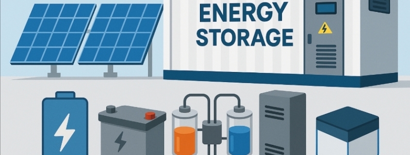
As the demand for reliable renewable energy grows, Battery Energy Storage Systems (BESS) have become an essential part of modern power infrastructure. But did you know that not all batteries are the same? In this post, we’ll break down the top 5 battery technologies used in BESS and help you understand their advantages, limitations, and typical applications.
1. Lithium-Ion Batteries: The Most Popular Choice
Lithium-ion batteries are by far the most common battery technology used in BESS today. Their high energy density, long cycle life, and declining costs make them ideal for everything from residential storage to utility-scale projects.
Pros:
High energy density
Long lifespan (up to 15 years or more)
Good round-trip efficiency (90%+)
Cons:
Sensitive to temperature
Fire risk if not properly managed
Where they fit: Perfect for grid balancing, renewable integration, and behind-the-meter storage.
2. Lead-Acid Batteries: Reliable and Cost-Effective
Although older than other battery technologies, lead-acid batteries are still widely used in BESS for their low upfront cost and proven track record.
Pros:
Low capital cost
Mature and well-understood technology
Easy to recycle
Cons:
Lower energy density
Shorter cycle life (typically 3–5 years)
Heavier and larger footprint
Where they fit: Best for backup power and applications where budget constraints are tight and space is not an issue.
3. Flow Batteries: Flexibility for Long-Duration Storage
Flow batteries (like vanadium redox) store energy in liquid electrolytes that flow through a cell stack. They’re gaining attention for large-scale, long-duration storage projects.
Sodium-sulfur batteries are high-temperature batteries that deliver large amounts of energy for longer durations. Utilities have used them for grid support and load leveling.
Pros:
High energy density
Suitable for large-scale, long-duration storage
Long cycle life
Cons:
Operate at high temperatures (300°C+)
Safety and material challenges
Where they fit: Best for utility-scale BESS applications where space and temperature control are manageable.
Where they fit: Promising for future BESS projects once commercialization and scalability improve.
How to Choose the Right Battery Technology for Your BESS
Choosing the best battery for your energy storage project depends on your goals: ✅ Do you need high energy density? → Lithium-ion or solid-state. ✅ Is low upfront cost key? → Lead-acid might work. ✅ Do you want long-duration storage? → Consider flow or sodium-sulfur batteries. ✅ Looking to future-proof? → Keep an eye on solid-state technology.
Always balance cost, safety, lifespan, efficiency, and your specific use case when selecting battery technologies for BESS.
It depends on the technology: lithium-ion can last 10–15 years, flow batteries up to 20 years, and lead-acid about 3–5 years.
Q4: What’s the safest battery for BESS?
Solid-state batteries promise enhanced safety because they have no flammable liquid, but they’re not yet widely available. Proper BMS (battery management systems) also play a big role in safety.
Q5: Can I mix different battery technologies in one BESS?
Technically, it’s possible but complex. Most projects stick with one type to simplify design, maintenance, and management.
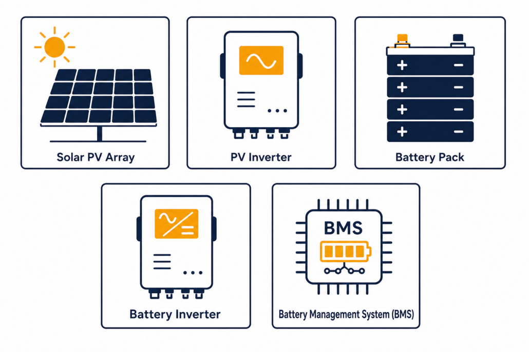
BESS architectures refers to the system design that connects batteries, power electronics, and control systems in a battery energy storage system. A typical BESS architecture includes battery modules, battery management systems (BMS), power conversion systems (PCS), and energy management systems (EMS) that work together to store and deliver electricity efficiently.
Battery energy storage systems are now critical infrastructure for renewable energy integration and grid stability.
What is a BESS Architecture?
A BESS architecture is the overall design and arrangement of the hardware and software components that make up the energy storage system. This includes the batteries, Battery Management System (BMS), Power Conversion System (PCS), control systems, and the way they are integrated and operated.
Why Understanding BESS Architecture is Important
The architecture determines how efficiently a BESS can store and deliver energy. It affects safety, scalability, cost, and performance. A well-designed BESS architecture ensures optimal energy usage, reduces losses, and prolongs battery life.
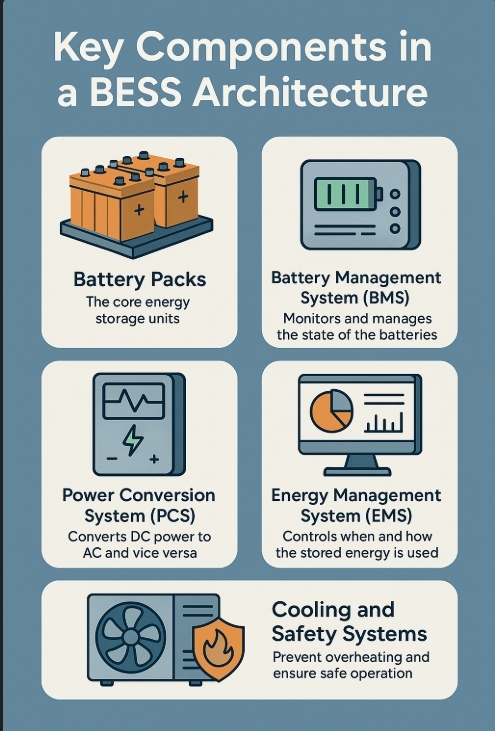
Key Components in a BESS Architecture
A typical BESS architecture includes:
Battery Packs: The core energy storage units.
Battery Management System (BMS): Monitors and manages the state of the batteries.
A modular architecture allows scaling up the system by adding standardized battery modules. This is common in containerized BESS solutions.
Advantages:
Easy scalability.
Simplified maintenance.
Disadvantages:
Initial setup can be more expensive.
4. Hybrid BESS Architecture
This combines features of both AC and DC coupling. It is ideal for complex systems requiring high flexibility.
Advantages:
Maximizes energy capture.
Adapts to different grid conditions.
Disadvantages:
More complex design and higher upfront costs.
How to Choose the Right BESS Architecture
When selecting a BESS architecture, consider:
Project Size: Small residential vs. large utility-scale.
Energy Goals: Backup power, peak shaving, grid services.
Budget: Upfront cost vs. long-term savings.
Scalability: Future expansion needs.
Consult with experienced energy consultants to ensure the architecture matches your project’s requirements.
What are the Benefits of a Good BESS Architecture?
A well-planned BESS architecture provides:
Higher Efficiency: Less energy lost during storage and conversion.
Better Reliability: Consistent performance over time.
Improved Safety: Lower risk of overheating or failure.
Cost Savings: Optimized use of energy reduces utility costs.
Questions About BESS Architectures
What is the difference between AC-coupled and DC-coupled BESS?
The main difference is where the battery connects to the system. AC-coupled uses a separate inverter, while DC-coupled shares an inverter with solar PV.
Can BESS be retrofitted into existing solar systems?
Modular BESS architectures are ideal for projects that need easy scalability and flexibility. However, they can have higher upfront costs.
Final Thoughts on BESS Architectures
Understanding Battery Energy Storage System architectures is key to building efficient, safe, and future-ready energy storage solutions. Whether you’re installing a residential system or a large grid-connected project, choosing the right BESS architecture can maximize your return on investment and help you get the most from your renewable energy.
Bi-directional inverters are becoming a game-changer in modern energy solutions, especially within Power Conversion Systems (PCS). Whether in residential solar setups or large-scale Battery Energy Storage Systems (BESS), bi-directional inverters ensure seamless power flow in both directions—charging and discharging—between sources, storage units, and the grid. This blog post explores how they work, why they matter, and how they power smarter energy infrastructure.
What Is a Bi-Directional Inverter?
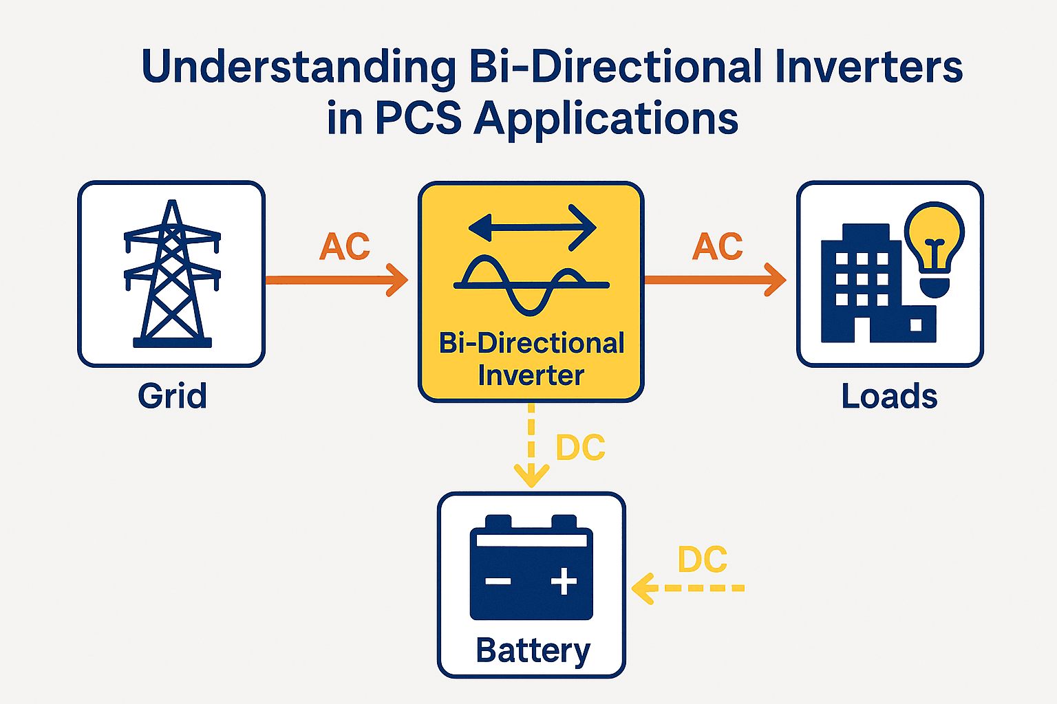
A bi-directional inverter is an advanced power electronic device that can both convert DC to AC (inverter mode) and AC to DC (rectifier mode). This dual functionality allows energy to move in two directions:
From the grid to batteries (charging)
From batteries to the grid or loads (discharging)
In PCS applications, this is crucial for load balancing, backup power, demand response, and optimizing energy costs.
Why Are Bi-Directional Inverters Important in PCS?
Power Conversion Systems (PCS) act as the interface between the energy storage system and the grid. The integration of bi-directional inverters offers several key advantages:
1. Grid Support and Frequency Regulation
They can feed power back into the grid or absorb it as required, enabling voltage/frequency stabilization, which is critical in renewable energy-heavy grids.
2. Flexible Load Management
During peak demand or outages, PCS with bi-directional inverters can redirect stored energy to critical loads.
3. Renewable Integration
They allow solar or wind energy to be stored and reused later, smoothing out the intermittency of renewables.
How Do Bi-Directional Inverters Work in PCS?
Charging Mode (Rectification)
When there’s excess power—such as from solar panels or the grid during off-peak hours—the inverter converts AC to DC and stores it in the battery system.
Discharging Mode (Inversion)
When power is needed, the stored DC energy is converted back to AC and used to power loads or sent to the grid.
This seamless switch between modes is managed by intelligent control algorithms within the PCS.
Applications of Bi-Directional Inverters in PCS
1. Battery Energy Storage Systems (BESS)
Large-scale storage units rely on bi-directional inverters for charge-discharge cycles, especially for grid-tied systems.
2. Microgrids
Enable isolated power operation and load sharing between solar, diesel generators, and batteries.
3. EV Charging Stations
Allow for vehicle-to-grid (V2G) energy transfer, where EVs serve as energy reserves.
4. Home and Commercial Energy Systems
Support self-consumption, energy arbitrage, and backup power during grid failure.
Key Technical Features of Bi-Directional Inverters
Smart Control Systems for dynamic energy flow management
Safety Mechanisms: Isolation, over-voltage, and thermal protection
These features make bi-directional inverters indispensable for smart energy ecosystems.
Benefits of Using Bi-Directional Inverters in PCS
Benefit
Explanation
Grid Interaction
Enables export/import of power to/from the grid
Energy Cost Optimization
Charge when prices are low; discharge when high
Resilience & Backup
Provide power during outages or peak load times
Renewable Maximization
Store excess solar or wind energy for future use
System Longevity
Controlled charge/discharge cycles improve battery life
Challenges and Considerations
Despite their many benefits, bi-directional inverters come with some technical and operational considerations:
Initial Cost: More complex and expensive than traditional inverters
System Complexity: Requires advanced control systems and integration
Regulatory Compliance: Must adhere to grid codes and safety standards
Thermal Management: Bidirectional use generates more heat, demanding better cooling solutions
Q&A About Bi-Directional Inverters
Q1: Can I use bi-directional inverters with solar panels?
Yes! They are ideal for solar systems combined with battery storage, allowing energy to be stored and used efficiently.
Q2: What makes them different from normal inverters?
Unlike regular inverters that only convert DC to AC, bi-directional inverters work both ways, supporting dynamic energy flows.
Q3: Are they suitable for off-grid systems?
Absolutely. In off-grid and hybrid systems, they provide enhanced energy control and backup capabilities.
Q4: Do they require special batteries?
Not necessarily, but high-efficiency systems often pair them with lithium-ion or other advanced battery chemistries for better results.
Real-World Use Case: Bi-Directional PCS in Smart Grid
In a commercial solar + storage project, a bi-directional PCS enables the facility to charge batteries during sunlight hours and discharge during peak demand, saving thousands on utility bills. The same system also provides blackout protection and participates in demand response programs, generating revenue.
Final Thoughts
Bi-directional inverters are at the heart of modern Power Conversion Systems. They’re more than just a technical upgrade—they’re a necessity for efficient, flexible, and intelligent energy management. As renewable energy and distributed generation continue to rise, so will the importance of these dual-purpose devices.
If you’re planning a BESS project, upgrading your commercial energy system, or simply aiming for smarter energy use, make sure to explore bi-directional inverters. They’re not just about converting power—they’re about empowering the future.
Energy arbitrage is the simplest revenue strategy in battery storage. A battery charges when electricity is cheap. Then, it discharges when electricity is expensive. The gap between those two prices is the spread. Capturing that spread is the entire strategy.
However, the full spread is never pure profit. Efficiency losses shrink it. Battery wear shrinks it further. This guide walks through how the strategy actually earns money, which costs cut into that revenue, and how to calculate the spread a project truly needs. For how this fits alongside other revenue streams, see our C&I BESS economics guide and our peak shaving vs. load shifting comparison.
How the Strategy Works
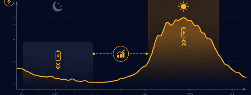
The pattern repeats daily. First, prices drop overnight, when demand is low. A battery charges during these cheap hours. Then, prices climb during the day. They often peak on hot afternoons, when air conditioning load surges. As a result, the battery discharges during these expensive hours, selling stored energy back at the higher rate.
Market structure shapes how much a project can actually earn. Deregulated markets tend to see more price swings, and those swings are what create opportunity in the first place. Grid congestion adds a second layer of upside. When transmission lines hit their limits, prices can vary sharply by location. So, a battery placed in the right zone can capture that gap too, on top of the daily time-based one.
Three Hidden Costs That Cut Into Your Margin
A visible price gap doesn’t automatically mean a profitable trade. Three factors quietly shrink that spread before it becomes real revenue.
Round-trip efficienc:. No battery returns 100% of the electricity it stores. Lithium-ion systems typically land in the 83–92% range, depending on chemistry, C-rate, and cooling. In other words, 10 kWh charged in might only return 8.5–9.2 kWh usable. Because of this, the sell price has to clear the buy price by more than the visible gap suggests — not just match it.
Battery degradation: Each cycle wears the battery down a little. In fact, one widely cited analysis of MISO market data found that degradation cut arbitrage revenue by roughly 12–46%, depending on the model used. This is easy to overlook, since it’s tempting to model efficiency losses and stop there.
Market fees and upkeep: Wholesale trading usually carries transaction fees. Meanwhile, the storage system itself needs ongoing maintenance. Both come out of the spread before any of it reaches the bottom line.
Put together, these three costs mean the sticker-price spread overstates the real opportunity. So, a strategy needs enough room to absorb all three and still turn a profit.
Calculating the Spread You Actually Need
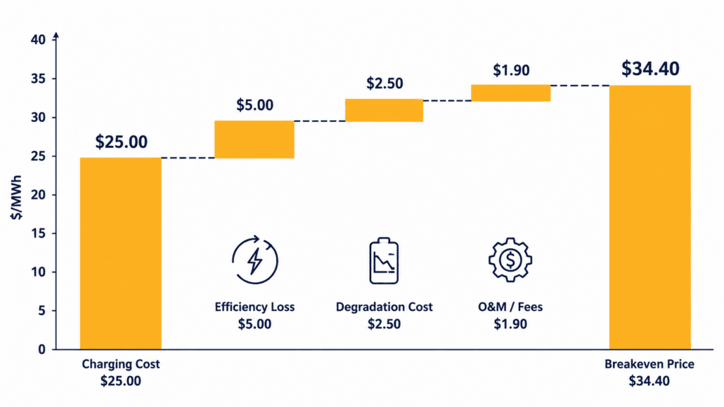
Think of this as your breakeven point — the minimum price gap before the strategy is worth pursuing. Here’s the formula:
Here’s how that plays out in a simple, illustrative example:
Metric
Value
Off-peak charging cost
$25/MWh
Round-trip efficiency
88%
Effective charging cost
$25 ÷ 0.88 = $28.40/MWh
Degradation cost per cycle (illustrative)
$4/MWh
O&M and market fee allocation (illustrative)
$2/MWh
Breakeven discharge price
$28.40 + $4 + $2 = $34.40/MWh
In this example, the battery needs to sell above $34.40/MWh just to break even. That’s well above the $25/MWh most people assume is the real bar. Anything captured beyond that line becomes genuine margin. This is exactly why a headline spread can look attractive on paper, yet still produce thin or negative returns in practice.
What Actually Moves the Market
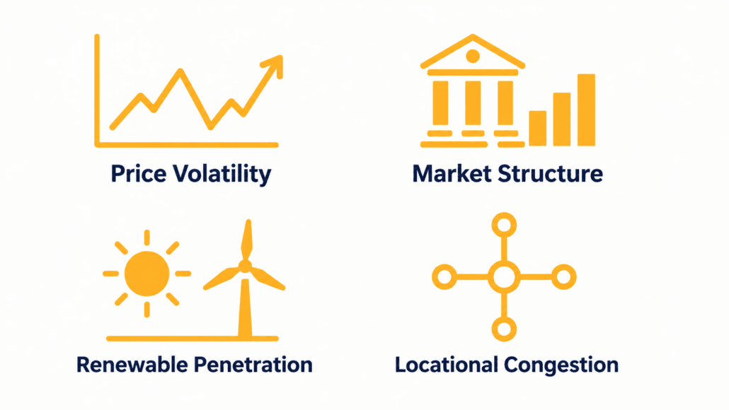
Price volatility: The wider and more frequent the daily swings, the more spread there is to capture. Flat, low-volatility tariffs, on the other hand, produce little to no opportunity.
Market structure: Deregulated wholesale markets generally offer more trading opportunity than fixed-tariff regulated ones.
Renewable penetration: Heavy solar and wind generation can trigger fast, large price swings — sometimes even negative prices during oversupply — which widens the gap available to a well-positioned battery.
Locational congestion: Grid bottlenecks create price differences between zones. Therefore, batteries sited near congestion points can capture that gap too, in addition to the daily one.
Analysts commonly benchmark this opportunity using “top-bottom” (TB) spreads — the gap between a market’s highest- and lowest-priced hours — as a standard way to compare potential across regions and durations. For broader market cost trends, the EIA’s battery storage market analysis is a useful reference point.
Why Most Projects Don’t Rely on This Alone
In practice, few BESS projects lean on a single revenue stream. Instead, layering in demand charge reduction, frequency regulation, or capacity payments spreads risk across multiple sources. As a result, this generally improves overall project economics compared to going it alone. See our peak shaving savings breakdown for how demand charge reduction stacks alongside this strategy, or our BESS cost per kWh and LCOS guide for the full project economics picture.
Merchant projects — ones relying entirely on wholesale price spreads with no fixed contract — carry real risk. Revenue depends on spreads that can shrink if market conditions or rules change. Contracted revenue, or a blended approach, generally reduces that exposure.
Energy Arbitrage Frequently Asked Questions
What is energy arbitrage in battery storage?
Energy arbitrage is the practice of charging a battery when electricity prices are low and discharging it when prices are high, capturing the price difference as revenue.
How much does round-trip efficiency affect energy arbitrage revenue?
Lithium-ion systems typically operate at 83–92% round-trip efficiency. That lost 8–17% means the discharge price must clear the charging cost by more than the visible spread suggests, not just match it.
Does battery degradation really cut into arbitrage profits?
Yes, substantially. Research using historical MISO market data found degradation reduced arbitrage revenue by roughly 12–46%, depending on the degradation model used. It’s one of the most commonly underestimated costs in arbitrage economics.
Is energy arbitrage alone enough to justify a BESS project?
Rarely as a standalone strategy. Most successful projects stack energy arbitrage with demand charge reduction, frequency regulation, or capacity payments to diversify revenue and improve overall project economics.
Next Steps
Ready to model your own numbers? Start with your local wholesale or time-of-use price spread. Then, apply the breakeven formula above, and compare it against your battery’s round-trip efficiency and degradation curve. For the full system cost picture, see our BESS cost per kWh and LCOS guide, or explore how this strategy stacks with other revenue streams in our C&I BESS economics guide.
⚡ Key Takeaways • A 100kW load run continuously (24/7) consumes 2,400 kWh per day. That daily energy figure is what drives solar and battery sizing. • Solar array size must be calculated for your worst realistic Peak Sun Hour (PSH) day, not your annual average — winter and cloudy-day sizing can be 2–2.5x larger than summer sizing. • Battery capacity depends on days of autonomy, Depth of Discharge (DoD), and round-trip efficiency — budget 3,000–10,000 kWh depending on backup duration. • The PCS/inverter is frequently undersized in DIY calculations — it must handle both the continuous 100kW draw and any surge/peak load, plus simultaneous charge and discharge in hybrid topologies. • LFP (LiFePO4) cells are the standard choice for stationary systems at this scale, rated for 3,000–5,000+ cycles at 80% DoD.
Planning solar panels and batteries to run a 100kW load around the clock? Sizing this correctly isn’t as simple as multiplying watts by hours, though.
Weather conditions, seasonal sunlight availability, cloudy-day derating, inverter sizing, and battery efficiency losses all factor in. Because of that, this guide walks through the full sizing process step by step, building toward a properly sized battery energy storage system (BESS) with formulas, worked examples, and a free interactive calculator.
📌 What You’ll Learn About Sizing for a 100kW Load
How to calculate required solar panel capacity for a continuous load
Why yearly weather data and Peak Sun Hours are critical to correct sizing
How to handle cloudy days and winter months without under-building
Battery sizing for different backup durations, DoD, and round-trip efficiency
How to size the PCS/inverter — the step most sizing guides skip
Battery chemistry, cycle life, and thermal management considerations at 100kW scale
Rough cost and payback framing so you can budget before requesting quotes
Example formulas and real-world worked values
🔧 Step 1: Understand Your 100kW Load
Let’s start with a 100kW load running 24 hours a day, every day.
100 kW × 24 hours = 2,400 kWh per day
That 2,400 kWh/day figure is your daily energy demand — it’s what solar and battery capacity are sized against.
If your load isn’t perfectly flat — for example, it dips to 60kW overnight and spikes to 130kW during a production shift — use the peak figure for PCS/inverter sizing. Use the daily kWh total instead (from a load profile or utility bill) for solar and battery sizing.
Averaging a variable load into a flat 100kW figure will, in short, undersize your inverter for the actual peak.
🌍 Step 2: Analyze Your Location’s Solar Irradiance for a 100kW Load
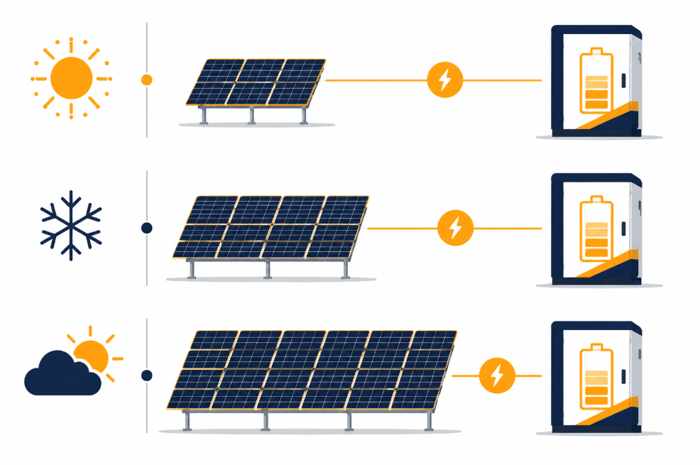
Your geographic location heavily influences how much sunlight you receive. Specifically, this is measured in Peak Sun Hours (PSH), the equivalent number of hours per day at 1,000 W/m² irradiance.
Location
Peak Sun Hours (avg)
Phoenix, USA
6.5 PSH
New Delhi, India
5.5 PSH
London, UK
2.8 PSH
👉 You can pull PSH data for your exact site from PVWatts (operated by the National Laboratory of the Rockies, formerly NREL), the NASA POWER Data Access Viewer, or commercial tools like Solcast. For a full breakdown of PSH by region and how it interacts with panel tilt, see our dedicated guides:
Sizing for the worst realistic case (cloudy-day PSH) rather than the annual average is, in fact, the single most common mistake in DIY sizing. In other words, it’s the difference between a system that works on a sunny July afternoon and one that keeps your load running in December.
🌥️ Why Consider Cloudy Days When Sizing a 100kW Load?
Even in a region with high annual irradiance, you’ll still, in fact, face stretches of poor sun exposure. For mission-critical applications, therefore, your system must:
Be oversized for worst-case scenarios, not average-case.
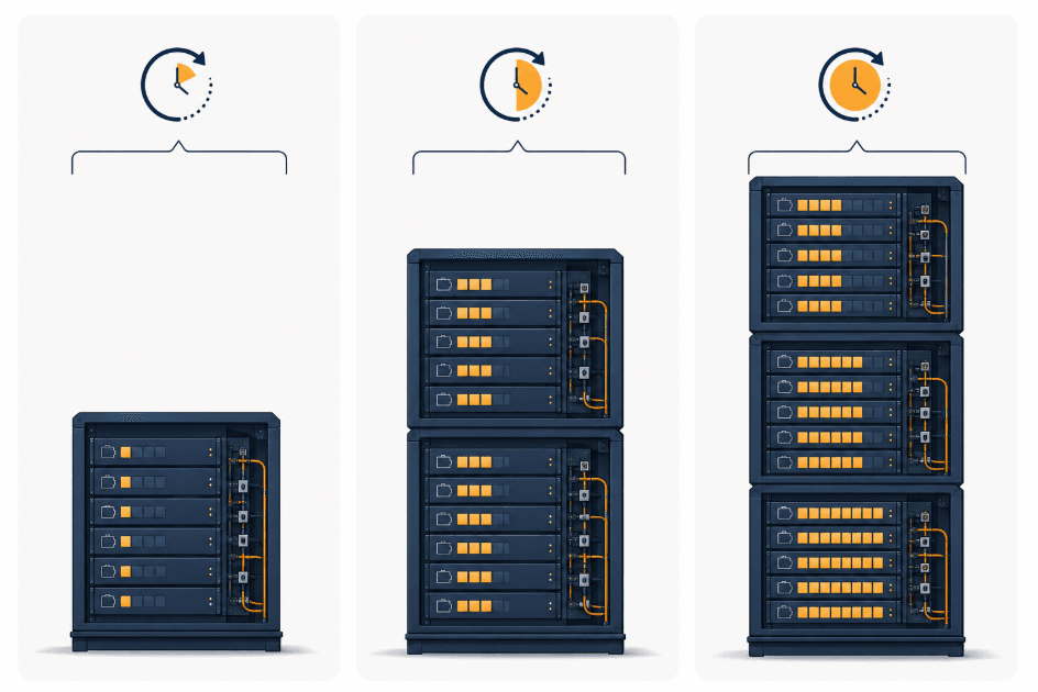
Include battery backup sized for 1–3 days of autonomy.
Use hybrid systems (generators or grid backup) where continuous uptime is non-negotiable.
❄️ Considerations for Winter Months
Winter brings three compounding effects:
Lower sun angles, which reduce effective irradiance on fixed-tilt arrays
Shorter daylight hours, which shrinks your PSH window
Snow cover in northern regions, which can fully block production for days
As a result, effective PSH drops and your dependence on stored energy or supplemental power increases. That’s exactly why the winter row in the Step 3 table above requires roughly 1.6x more solar capacity than the summer row.
⚡ Step 4: Size the Battery Energy Storage System for a 100kW Load
Ultimately, your BESS needs to store enough energy to power the load during non-sunny hours or outright weather/grid failures.
Formula:
Battery Capacity (kWh) = (Daily Load × Days of Autonomy) ÷ (DoD × Efficiency)
Daily Load = 2,400 kWh
Depth of Discharge (DoD) = 0.8
Round-trip Efficiency = 0.9
Backup Duration
Required Battery Capacity
1 Day
2,400 ÷ (0.8 × 0.9) ≈ 3,333 kWh
2 Days
4,800 ÷ (0.8 × 0.9) ≈ 6,667 kWh
3 Days
7,200 ÷ (0.8 × 0.9) ≈ 10,000 kWh
Note that these figures are usable energy requirements — rated (nameplate) capacity will need to be slightly higher once you account for BMS reserve margins and end-of-life capacity fade. For the difference between rated and usable capacity units, see Ah vs Wh Battery Capacity Explained, and for the general framework behind these backup calculations, see our Energy Storage Calculation Guide.
🔌 Step 5: Size the PCS / Inverter for Your 100kW Load (Often the Missing Step)
Solar array and battery capacity get most of the attention in sizing guides. However, the Power Conversion System (PCS) — the bidirectional inverter that moves power between panels, batteries, and load — is just as critical. In fact, it’s the component most DIY calculations undersize.
Specifically, your PCS needs enough continuous rating to handle the load, plus headroom for surge and simultaneous charge/discharge:
Continuous rating: must cover your 100kW continuous draw, not the average of a variable load profile.
Peak/surge rating: motor starts, compressor inrush, and HVAC cycling can spike 20–50% above continuous draw for a few seconds — undersized PCS units trip or clip during these events.
Simultaneous charge + discharge: in a hybrid solar + battery + load topology, the PCS may need to charge the battery from solar while discharging to load at the same time — size for the combined throughput, not just the larger of the two.
As a starting point, a reasonable figure for a 100kW continuous load is a 125–150kW PCS, though the correct number depends on your actual peak load profile and topology. For the functional breakdown of what a PCS does and how to evaluate one, see:
🔋 Battery Chemistry & Cycle Life for a Continuous-Duty 100kW Load
A 100kW load running 24/7 puts a battery through far more charge/discharge cycles per year than a typical backup-only installation. As a result, chemistry and cycle-life ratings matter more here than in a system that only discharges occasionally.
LFP (LiFePO4) is the standard choice for stationary systems at this scale: Tier-1 EV-grade LFP cells are typically rated 3,000–3,500 cycles at 0.5C / 80% DoD, with 120Ah-class prismatic cells often rated 3,500–6,000 cycles.
NMC offers higher energy density but lower cycle life and reduced thermal stability — generally a weaker fit for continuous-duty stationary storage than for space-constrained mobile applications.
Sodium-ion is an emerging alternative worth watching for cost-sensitive, cycle-heavy applications, though it currently trails LFP on energy density.
At 1–2 cycles per day, a 3,500-cycle-rated cell reaches end-of-life capacity (~80% of nameplate) in roughly 5–10 years. Therefore, factor this into both your battery oversizing margin and your long-term budget. For deeper comparisons:
🌡️ Thermal Management: Do You Need Liquid Cooling at This Scale?
A 3,000–10,000 kWh battery bank running near-continuous cycling generates meaningfully more heat than an occasional-backup system of the same size. Consequently, thermal management becomes a real design decision rather than an afterthought.
Air-cooled systems are simpler and cheaper, and remain viable for lower cycle-rate, moderate-climate installations.
Liquid-cooled systems hold tighter cell-to-cell temperature gradients, which matters directly for the cycle-life numbers above — sustained high temperatures accelerate capacity fade regardless of chemistry.
For continuous 0.5C–1C duty cycles in hot climates, liquid cooling is generally the safer long-term choice despite the higher upfront cost.
Install with adjustable tilt for seasonal optimization
TOPCon cells are, in fact, increasingly the default choice for higher-efficiency Tier-1 modules. For more detail, see our TOPCon Solar Cells guide on how they compare to standard PERC panels.
✅ Tips for Choosing Battery Cells for BESS
Use temperature-controlled (or liquid-cooled) enclosures for extreme climates
Choose Lithium Iron Phosphate (LFP) for safety and long cycle life at continuous-duty scale
Look for modular scalability so you can expand storage as load grows
Integrate with a proven BMS and EMS — don’t treat this as an afterthought
🔄 Hybrid Solutions for a Reliable 100kW Load
When powering a 100kW continuous load, therefore, it’s worth considering a hybrid setup:
Go fully off-grid: Solar + Wind + Battery — for redundancy in variable-weather regions
Add diesel backup: Solar + Battery + Diesel — for industrial backup where uptime is non-negotiable
Stay grid-connected: Solar + Grid + Battery — for grid-tied systems using the battery mainly for peak shaving and outage ride-through
💰 Estimating Total System Cost & Payback for a 100kW Load
Before requesting formal quotes, it helps to budget at a rough order of magnitude. Specifically, total installed cost scales with three line items: the solar array (per-watt installed cost), the battery bank (per-kWh installed cost), and the PCS/BOS/engineering package. Typically, the battery bank is the single largest line item at this scale given the 3,000–10,000 kWh range from Step 4.
Get exact per-watt and per-kWh figures from vendor quotes — these vary significantly by region, scale, and financing structure, so we intentionally don’t publish a single blended $/kWh figure here.
Payback period depends heavily on your alternative: offsetting diesel genset fuel and grid demand charges typically pays back faster than pure grid-tied offset in low-electricity-cost regions.
Model your specific numbers rather than relying on rule-of-thumb payback claims.
Battery for 2 days = 2,400 × 2 ÷ (0.8 × 0.9) ≈ 6,667 kWh
PCS sizing (per Step 5): 125–150 kW continuous, sized for the facility’s actual peak/surge profile
While static estimates give you a solid baseline, real-world engineering requires calculating system sizing interactively based on your specific geographical peak sun hours and target safety thresholds.
🧮 Interactive Solar & BESS Capacity Calculator
Use our professional sizing engine below to customize your numbers. Specifically, this tool automatically computes the balance between direct daytime consumption and the excess energy required to charge the battery bank for night or emergency runs.
☀️ Solar & BESS Capacity Calculator
📊 Recommended Sizing Results:
Daily Total Consumption: kWh/day
Required Solar Array Capacity: kWp
Required Battery Storage (BESS): kWh
Minimum Suggested PCS/Inverter: kW
🛠️ Sizing Definitions Explained
Daily Total Consumption (kWh): the total energy your system expends every day.
Required Solar Array Capacity (kWp): the nameplate rating of your panel configuration under Standard Test Conditions (STC), sized high enough to fill your BESS during operating hours.
Required Battery Storage (BESS, kWh): the gross storage capacity needed to survive weather downturns without exceeding safe Depth of Discharge (DoD).
PCS / Inverter Rating (kW): the continuous and surge power-handling capacity of the conversion system linking panels, batteries, and load — see Step 5 above.
📖 Recommended Sizing Resources for a 100kW Load
To fine-tune your inputs for the calculator above, explore our comprehensive technical guides:
Only if your load is flexible or you remain connected to the grid as a backstop. Otherwise, a continuous 100kW load with no grid connection and no battery has zero ride-through the moment the sun sets or a cloud rolls in.
Q: Should I oversize the battery or the solar array?
Both, in proportion to your climate. Specifically, cloudy regions need more solar oversizing to fill the same battery bank in fewer usable hours, while regions with frequent multi-day outages need more battery autonomy regardless of solar oversizing.
Q: What’s better — LFP or NMC batteries?
LFP is generally the safer, longer-cycle-life choice for stationary storage at this scale, while NMC’s higher energy density suits space-constrained mobile applications more than fixed installations.
Q: How big a PCS/inverter do I actually need for a 100kW Load?
Size for your actual peak draw plus surge headroom, rather than the 100kW continuous average. As a starting range, 125–150kW is reasonable, though you should pull your real load profile before finalizing (see Step 5).
Q: Do I need liquid cooling for a battery bank this size?
Not always — it depends on cycling frequency and climate. Continuous 0.5C–1C duty in hot climates benefits meaningfully from liquid cooling’s tighter thermal gradients, while lower cycle-rate systems in moderate climates can often stay air-cooled.
Q: How long will the battery bank last before it needs replacing?
Tier-1 LFP cells at 0.5C/80% DoD are typically rated 3,000–6,000 cycles. At roughly one full cycle per day, that’s a working life in the 8–14-year range before capacity fades to around 80% of nameplate, so budget your replacement schedule accordingly.
Q: Is grid-tied or off-grid better for a 100kW continuous load?
Grid-tied lets you undersize solar and battery relative to a true off-grid design, since the grid covers shortfalls. Off-grid or hybrid designs, on the other hand, are necessary wherever grid reliability can’t be trusted for a continuous critical load.
📌 Conclusion
Designing a solar + battery system for a 100kW load isn’t just about matching numbers. Rather, it’s about planning for the worst realistic day of the year, not the best.
In short, location-specific solar data, battery autonomy, PCS sizing, cell chemistry, thermal management, and cost all need to be part of your sizing strategy from the start, rather than bolted on after the array is already ordered.
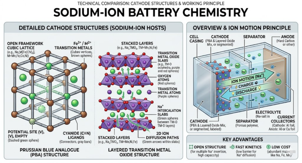
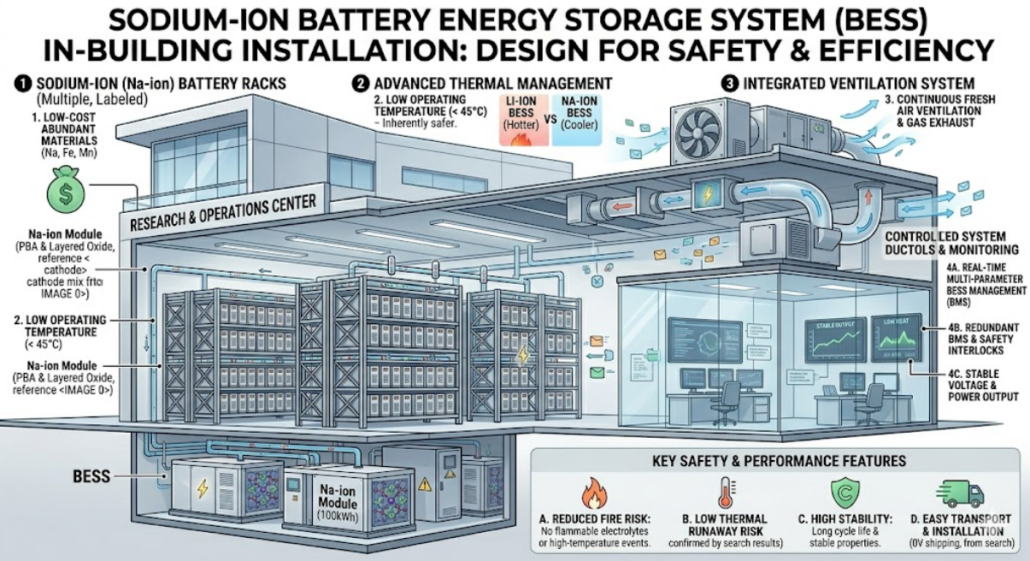
Sodium-ion battery safety explains how safely these batteries operate, store energy, and move through supply chains. Today, safety is a top concern in energy storage.
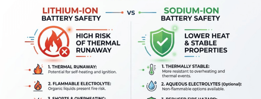
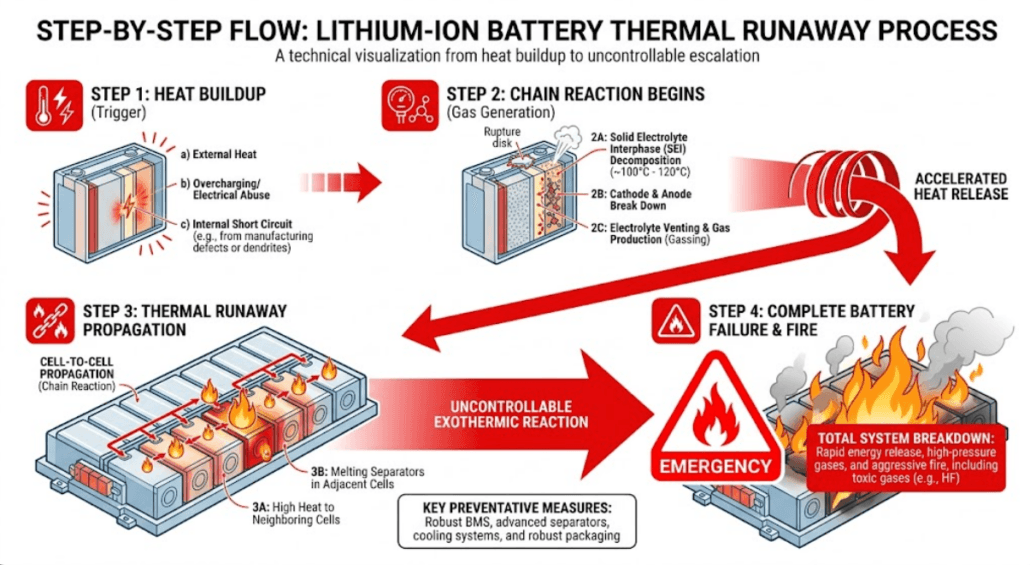
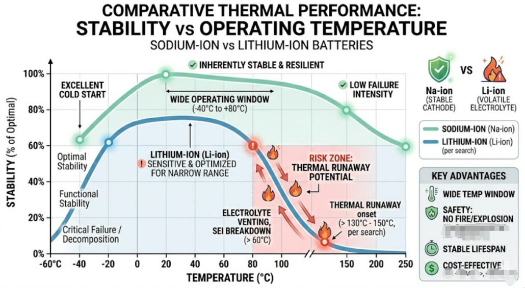
However, lithium-ion batteries still face fire risks. Thermal runaway remains a major issue. Because of this, safer alternatives are gaining attention. One strong option is sodium-ion technology.
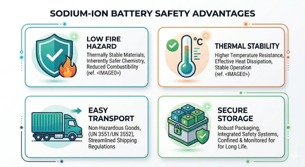
Sodium-ion batteries are safer because their chemistry is more stable. Unlike lithium, sodium does not react violently when exposed to stress. This significantly lowers the risk of a sudden fire or explosion.
Stable Electrolytes: The liquid inside a sodium battery is less likely to catch fire than the electrolytes used in lithium-ion systems.
Less Heat: Sodium-ion cells generate very little internal heat. This prevents the “domino effect” of overheating known as thermal runaway.
No Dendrites: Lithium batteries can grow tiny, sharp structures called “dendrites” that cause short circuits. Sodium chemistry naturally prevents these growths.
👉 Read more Sodium chemistry naturally prevents these growths. For a full look at how this technology works, check out our complete sodium-ion battery guide.
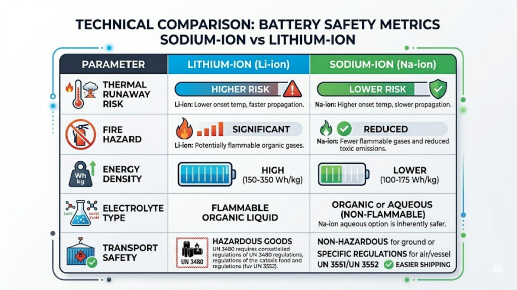
Sodium-Ion Battery Safety vs Lithium-Ion
A comparison helps clarify the difference.
Safety Factor
Sodium-Ion
Lithium-Ion
Thermal Runaway
Very low
Medium to high
Fire Risk
Low
High
Temperature Range
Wide
Limited
Electrolyte
More stable
Flammable
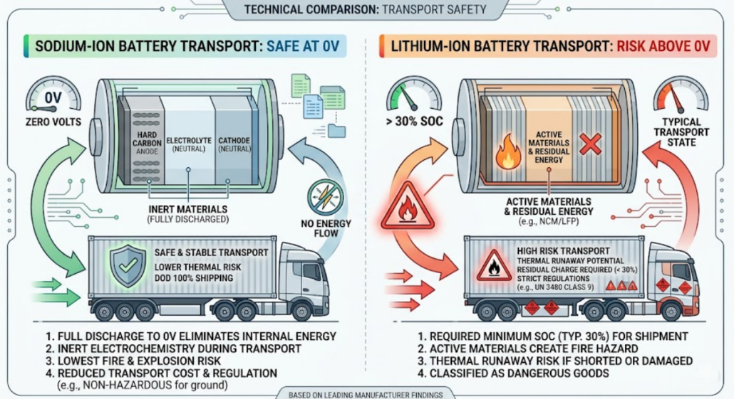
Transport State
0V safe
Partial charge required
🛡️ Live Battery Safety Risk Simulator
Select a critical battery stress factor to simulate safety performance behavior.
🟢 SODIUM-ION REACTION
High thermal stability. Runaway crystallization begins late at 250°C, producing minimal toxic smoke gas discharge emissions.
🔴 LITHIUM-ION REACTION
High risk of thermal runaway. Cellular decomposition triggers violently around 150°C, rapidly spreading oxygen-fed fire structures.
In contrast, lithium-ion batteries need more protection systems. Therefore, sodium-ion battery safety is often preferred in large installations.
As the world races toward a cleaner future, storing renewable energy efficiently is no longer optional—it’s essential. At the core of this transition is the Battery Energy Storage System (BESS). Among its many forms, the AC Coupled BESS stands out for its flexibility, reliability, and ease of integration. Whether you’re expanding an existing solar setup or starting fresh, this powerful configuration could be the key to true energy freedom. In this post, we’ll uncover what makes AC coupling special—and why it might just be the smarter choice for your energy journey.
AC coupling is a smart, scalable solution often used in retrofit projects, hybrid systems, and microgrids, offering flexibility in design and control.
Core Components of AC Coupled BESS
An AC Coupled BESS typically consists of the following key components:
1. Battery Pack
The heart of the system – stores energy chemically and discharges it as needed. Battery types include:
Lithium-ion (most common)
LFP (Lithium Iron Phosphate)
NMC (Nickel Manganese Cobalt)
Lead-acid (less common today)
2. Battery Management System (BMS)
Monitors and protects the battery cells by managing parameters like voltage, temperature, and charge/discharge rates. Prevents overcharging, deep discharging, and ensures system longevity.
3. Battery Inverter (Bidirectional Inverter)
This converts DC power from the battery into AC for grid compatibility, and vice versa during charging. Also known as a PCS (Power Conversion System) in utility-scale deployments.
4. Energy Meter
Monitors and measures the energy flow to and from the battery, PV system, grid, and loads. Helps in performance monitoring and utility compliance.
5. EMS (Energy Management System)
The brain of the system – it manages how and when the battery charges or discharges based on load demand, time-of-use pricing, grid signals, and PV generation.
6. Grid Connection / Load Panel
Where the system connects to the facility’s electrical infrastructure, enabling energy import/export and onsite consumption.
AC Coupled Battery Storage: How Energy Moves Through the System
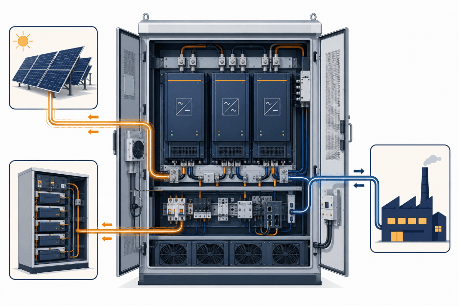
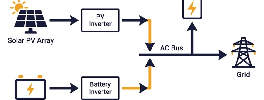
AC-coupled battery storage keeps the battery and the solar PV array on entirely separate circuits until they meet at the AC side of the system. During the day, the solar PV inverter generates AC electricity directly from the array. Any excess AC power not used on-site routes to the battery inverter, which converts it to DC to charge the battery — a process the BMS manages for safety and battery health.
When load demand exceeds generation, such as at night, the battery inverter reverses that conversion: it takes the battery’s stored DC power and converts it back to AC to supply the home or facility. Depending on how the system is configured, it can also import power from the grid or export excess energy back to it, enabling peak shaving, backup power, and participation in demand response programs.
This separation between the solar and battery inverters is what makes AC-coupled energy storage the more common retrofit choice: because the battery inverter operates independently, you can add AC-coupled battery storage to a solar system that’s already running without reconfiguring the existing PV inverter or rewiring the array. The U.S. Department of Energy has funded toolkit development specifically to simplify this kind of retrofit interconnection as battery storage adoption grows alongside existing solar installations.
The Role of the Battery Inverter in AC Coupled BESS
In an AC-coupled BESS, the battery inverter does the same core job as a hybrid inverter in a DC-coupled system, but it works alone rather than sharing duties with the solar inverter. It converts DC power from the battery to AC when discharging, and AC back to DC when charging, and it manages that conversion independently of whatever the solar PV inverter is doing at the same time.
Because the battery inverter operates on its own, AC-coupled systems can size, replace, or upgrade the battery inverter without touching the solar side at all — one of the main reasons AC-coupled storage stays the easier architecture to retrofit or expand in phases.
You can scale solar and battery systems independently. Ideal for adding more storage or generation capacity later.
3. Enhanced Redundancy
Separate inverters mean that if the solar or battery inverter fails, the other can still operate independently.
4. Flexible Control Strategies
AC coupling allows integration of diverse energy sources (wind, genset, hydro) and supports complex control logics using EMS.
5. Supports Microgrids & Off-Grid Applications
Crucial for backup power and remote areas. Works well in microgrids with multiple power sources and fluctuating load demands.
6. Time-of-Use Optimization
Charge batteries when electricity is cheap, and discharge during peak pricing. This helps reduce electricity bills significantly.
7. Grid Services Compatibility
Advanced systems can provide frequency regulation, voltage support, and participate in ancillary service markets.
AC Coupled vs. DC Coupled BESS
The core difference: AC-coupled systems use two separate inverters — one for solar, one for the battery — connected on the AC side. DC-coupled systems share a single inverter, with the battery and PV array on the same DC bus. AC-coupled is generally the easier, more flexible retrofit path; DC-coupled tends to be more efficient and lower-cost for new-build projects.
Commercial and Industrial facilities needing power backup or time-of-use optimization.
Remote microgrids with multiple sources of energy.
Retrofit projects adding batteries to an existing solar system.
Utility-scale grid support installations where power export, voltage regulation, and load shifting are required.
Frequently Asked Questions
What does “AC-coupled” mean?
AC-coupled means the solar PV array and the battery each connect to the grid through their own separate inverter, meeting only on the AC side of the system rather than sharing a DC bus.
What is an AC-coupled inverter?
An AC-coupled inverter is the dedicated inverter that connects a battery to the AC side of a solar-plus-storage system. It operates independently from the solar PV inverter, which is why AC-coupled systems use two inverters instead of one.
Is BESS the same as a PV system?
No. BESS (Battery Energy Storage System) refers specifically to the battery and its supporting hardware. A PV system refers to the solar panels and their inverter. Most solar-plus-storage projects combine both, but they’re distinct pieces of equipment with separate specifications.
What’s the difference between AC coupling and DC coupling?
Can AC-coupled batteries connect to any solar system?
In most cases, yes. Because AC-coupled batteries connect on the AC side through their own inverter, they can typically be added to an existing solar installation without modifying the PV array or its inverter, which is why AC-coupling is the more common retrofit choice.
Conclusion
AC Coupled BESS is a versatile and future-proof energy storage architecture. While it involves slightly more components and costs compared to DC coupling, the flexibility, redundancy, and modularity it offers make it a favorite for professionals designing hybrid systems, microgrids, and energy-resilient facilities.
Whether you’re an engineer, energy consultant, or business owner exploring storage solutions – understanding how AC coupled BESS works is key to making smarter energy decisions.
Need help sourcing or evaluating AC Coupled BESS systems? As a New Energy Consultant with over 13 years in China’s energy sector, I help global clients source reliable BESS products, conduct factory audits, and ensure full compliance with international standards.
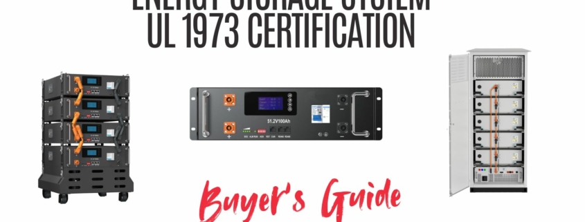
As energy storage technologies power everything from homes to large-scale grids, safety and compliance have become non-negotiable. Among the most important safety benchmarks is UL 1973 certification, the globally recognized standard for stationary batteries and energy storage systems.
This certification validates that a battery has passed rigorous safety and performance tests, ensuring it can operate reliably under real-world conditions. For manufacturers, system integrators, and project developers, achieving UL 1973 certification is not only about compliance—it is about protecting customers, enabling market access, and building trust.
What Is UL 1973 Certification?
UL 1973, formally titled “Batteries for Use in Stationary, Vehicle Auxiliary Power, and Light Electric Rail Applications,” defines the testing requirements for rechargeable batteries used in non-automotive settings.
In simpler terms, if you are producing a Battery Energy Storage System (BESS) or a stationary backup solution, UL 1973 is the certification you need to prove safety.
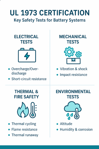
It is a safety certification for stationary and rail-use rechargeable batteries that validates performance under electrical, mechanical, and thermal stress.
Q2. Is UL 1973 mandatory for all batteries?
No, it applies primarily to stationary and auxiliary power systems, not automotive traction batteries (those follow UL 2580).
Q3. How long does certification take?
Typically 6–12 months, depending on battery complexity and lab availability.
Q4. How does UL 1973 relate to UL 9540?
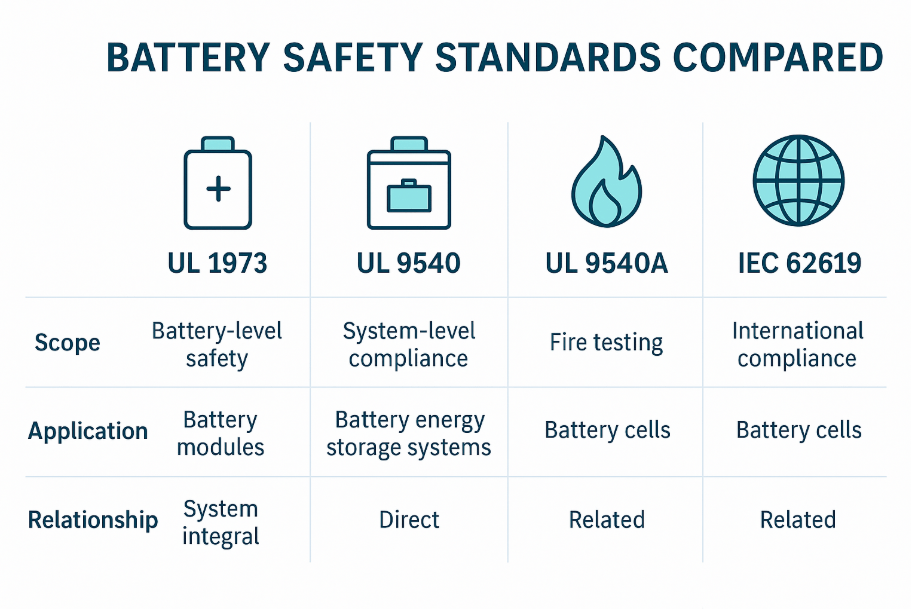
UL 1973 ensures the safety of the battery itself, while UL 9540 covers the entire storage system. Most UL 9540 certifications require UL 1973-approved components.
Q
Final Thoughts
In the competitive energy storage landscape, UL 1973 certification is more than just a box to check—it is your gateway to trust, compliance, and market success. Whether you’re developing a new stationary storage solution or scaling up production, aligning with this standard protects your customers, your business, and your brand.
At Sunlith Energy, we combine technical expertise with compliance experience to help you achieve certification faster and more cost-effectively.