
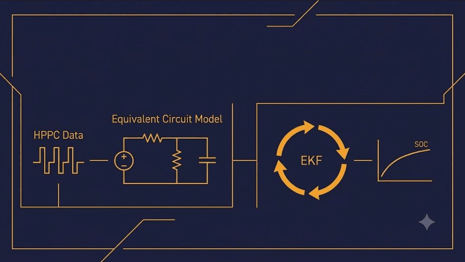
EKF SOC Estimation Design for LFP BESS: Model Parameterization and Covariance Tuning
Every BESS reports a state of charge number to its EMS. That number drives dispatch. It drives revenue. It drives warranty math too. Good EKF SOC estimation design keeps that number honest. It stays honest even as cells age. It stays honest as temperatures shift and load patterns change. This guide covers steps most SOC articles skip. First, build the model. Then fit it from test data. Then tune the filter so it corrects errors fast, without chasing sensor noise.
| ⚡ Quick Answer EKF SOC estimation design means building a circuit model of the cell from HPPC test data, then tuning the Kalman filter so it trusts the model at rest and trusts the sensors under load. Get the model wrong, or the tuning wrong, and the filter either drifts like open-loop counting or jumps around on every current spike. |
From HPPC Data to an Equivalent Circuit Model
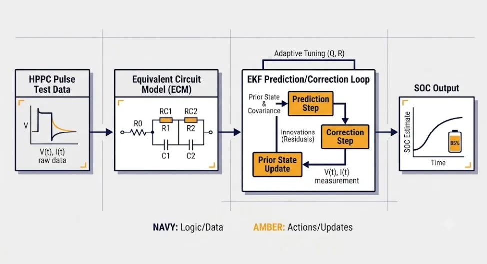
An EKF cannot estimate what it cannot model. So the first step in EKF SOC estimation design is building an equivalent circuit model, or ECM. This model describes how terminal voltage responds to current. A simple, first-order ECM uses three parts: an open-circuit voltage source, a series resistance, and one resistor-capacitor pair for voltage relaxation. Many BESS projects use a second-order ECM instead. That adds a second RC pair. It separates fast charge-transfer effects from slower diffusion effects.
Extracting Parameters from Pulse Data for EKF SOC Estimation Design
HPPC testing supplies the raw data for this step. It is the same pulse-and-rest method used to build a DCIR lookup table for a dynamic cutoff. Each pulse reveals resistance from the instant voltage step. It reveals RC time constants from the relaxation curve after. Good EKF SOC estimation design fits these parameters at every SOC and temperature step in the test matrix. Do not fit just once at a nominal point. LFP’s resistance shifts across the full range, and so does its relaxation behavior.
Why the Flat OCV Curve Still Matters
LFP’s OCV-SOC curve is flat between 20% and 80%. This is why Coulomb counting and OCV lookup drift on their own. It is also why EKF SOC estimation design must treat the OCV-SOC table as a core model input, not an afterthought. A weak OCV curve in the flat zone gives the filter almost nothing to correct against, right where correction matters most.
Tuning the Filter: The Core of EKF SOC Estimation Design
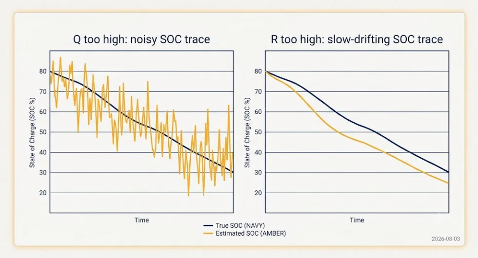
This filtering approach builds on the adaptive extended Kalman filter method for battery state estimation, adapted here specifically for LFP’s flat OCV-SOC curve. For the three underlying SOC methods this design builds on, our BMS SOC estimation methods guide covers OCV lookup, Coulomb counting, and Kalman filtering at a conceptual level. Once the ECM exists, the filter itself needs tuning. Two settings control its behavior. Process noise covariance, called Q, sets how much the filter trusts its own model between updates. Measurement noise covariance, called R, sets how much it trusts each voltage reading. Together, these two numbers set the correction strength. This step is the heart of real EKF SOC estimation design work.
What Happens When Q Is Too High
A high Q value tells the filter its model cannot be trusted. So it leans hard on every voltage sample instead. But on LFP’s flat curve, that sample carries almost no SOC signal across most of the range. The estimate turns noisy and jumpy during normal cycling. This is a common failure. The filter looks fine on a bench test. Then it behaves badly once deployed against real load profiles.
What Happens When R Is Too High
The opposite mistake sets R too high. That tells the filter to distrust the voltage reading. The estimate then acts like open-loop Coulomb counting. It drifts slowly over days, since it never truly corrects against sensor data. Both mistakes produce the same bad outcome: a confident but wrong SOC number. That is worse for dispatch accuracy than a system that visibly struggles.
A Practical Starting Point for Tuning
Start Q and R from real numbers. Use your measured sensor noise floor. Use your HPPC fit residuals. Then adjust by testing against a validation cycle the model has not seen before. An adaptive approach helps too. Let R scale up automatically during high-current transients, when voltage sag dominates the signal. This improves robustness without manual retuning for every duty cycle.
Where Estimation Error Spreads to the Other Two Problems
EKF SOC estimation design does not stand alone. A biased estimate feeds two other systems directly. First, it distorts the balancer’s target. If the estimator reports a false high SOC on one cell, the balancer under-corrects a real gap, and that gap grows — see our in-service cell imbalance guide for how that plays out at the pack level. Second, it distorts cutoff logic. For the full LFP-specific voltage and temperature parameters this estimator design has to respect, see our BMS for LiFePO4 batteries guide. A DCIR-adaptive cutoff uses the same current and temperature inputs the estimator uses. A wrong SOC estimate near empty can trigger a cutoff too early, or too late, relative to the cell’s true state.
This is why SOC estimation belongs beside cell balancing and cutoff design, not as a separate topic on its own. The three systems share inputs. In a well-built BMS, they should share state too, not run as separate, disconnected modules— our integrated BMS control architecture guide covers how to build that shared state layer.
Validating EKF SOC Estimation Design Before Deployment
EKF SOC estimation design is not finished once tuning looks good on paper. Before field deployment, test the tuned filter against a real dispatch profile. Do not just replay the HPPC pulse sequence. A filter can track a clean pulse test well, then still fail on a real profile full of irregular current swings. At the end of validation, compare the filter’s estimate against a full charge-discharge cycle. That full cycle gives a true anchor point. The filter’s own reported error cannot hide from it.
Re-Validating EKF SOC Estimation Design as Cells Age
ECM parameters from beginning of life will not hold for the system’s full service life. Resistance grows. Capacity fades. So the same periodic HPPC re-test that refreshes a DCIR-adaptive cutoff table should also refresh the EKF’s model. Tie both refresh cycles to one shared SOH milestone. That keeps the estimator and the cutoff logic working from the same, current view of the pack.
Key Takeaways
EKF SOC estimation design starts with a circuit model fitted from HPPC pulse data, across the full SOC and temperature matrix. Process and measurement covariance tuning decides whether the filter trusts its model or its sensors, and getting either one wrong produces a noisy or a slow-drifting estimate. SOC estimation error never stays contained. It spreads into balancing decisions and cutoff timing too. Re-validate the model often, on the same schedule as other resistance-based BMS recalibrations.
Frequently Asked Questions
Does EKF SOC estimation design need a first-order or second-order model for LFP?
A second-order model captures LFP’s diffusion behavior more accurately. It is standard for utility-scale and precision work. A first-order model is lighter on BMS processing budget. It can be enough for smaller residential systems with lighter accuracy needs.
How often should the EKF model be re-tuned?
Tie re-tuning to the same SOH milestone used for other resistance-based recalibrations. That is commonly every 500 to 1,000 cycles, or whenever a capacity or resistance trend crosses a set threshold, rather than a fixed calendar date.
Can a poorly tuned EKF cause a false cutoff trip?
Yes. A dynamic cutoff calculates its trip voltage from the same current and modeled resistance the estimator uses. So a biased SOC estimate near empty can shift the effective cutoff point away from the cell’s true safe limit.
Further Reading
BMS SOC Estimation Methods Explained
BMS for LiFePO4 Batteries: Requirements and Parameters
Battery Management System (BMS) Explained








Trackbacks & Pingbacks
[…] EKF SOC Estimation Design for LFP BESS […]
[…] only saw moderate temperatures during characterization will estimate poorly outside that range. Our EKF SOC estimation design guide and DCIR-adaptive cutoff design guide both assume the underlying test matrix covers real operating […]
[…] to see this built out in practice? Our EKF SOC estimation design guide walks through the equivalent circuit model, HPPC-based parameterization, and Q/R […]
[…] itself. A biased estimate feeds false signals into the other two layers, discussed below. Our EKF SOC estimation design guide covers the model-building and covariance-tuning steps in […]
[…] EKF SOC Estimation Design for LFP BESS […]
[…] voltage response to extract resistance at each point. This is the same underlying test data an EKF SOC estimation design uses to build its own equivalent circuit model. A project running one HPPC campaign can feed both […]
Leave a Reply
Want to join the discussion?Feel free to contribute!