

Designing Against In-Service Cell Imbalance in LFP BESS
Cell matching before pack assembly sets a good starting point. But it does not stay good forever. In-service cell imbalance builds up over years. It builds long after the pack leaves the factory well matched. Heat, aging, and cycling all pull cells apart again. This guide covers the design choices that slow that drift. It covers thermal layout, balancing topology, and how imbalance control ties back into SOC estimation.
| ⚡ Quick Answer In-service cell imbalance grows mainly from two sources after assembly: uneven pack temperature, and the uneven aging that follows from it. Good thermal design and the right balancing topology both slow this drift. Neither one fixes a pack that started out badly matched. |
Why In-Service Cell Imbalance Differs from Factory Mismatch
Factory cell matching solves the starting-point problem. Our cell matching before pack assembly guide covers that stage in depth. It groups cells by voltage, capacity, and resistance before assembly. In-service cell imbalance is a different, ongoing problem, however, because even a well-matched pack drifts apart over time. The BMS balances small gaps every cycle. But the size of that gap depends on design choices made outside the BMS itself.
The Feedback Loop Between Heat and Aging
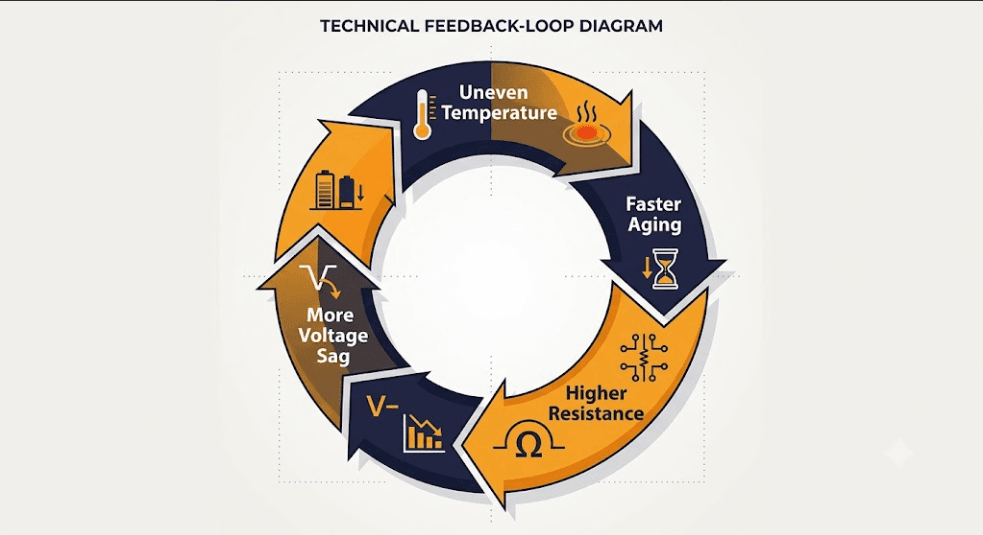
This pattern matches published research on thermal gradients in lithium-ion packs, which found that uneven internal temperature drives inhomogeneous degradation and resistance growth well before a pack reaches end of life on paper. Heat is the main driver of in-service cell imbalance. A cell that runs hotter than its neighbors ages faster. It loses capacity faster and, as a result, it gains resistance faster too. Consequently, that resistance rise makes it sag more under load. More sag can make it run hotter still, at the same current. This is a feedback loop. Left unmanaged, a small temperature gap can grow into a real capacity gap. This can happen within a few years of daily cycling.
Designing Thermal Layout to Limit Imbalance
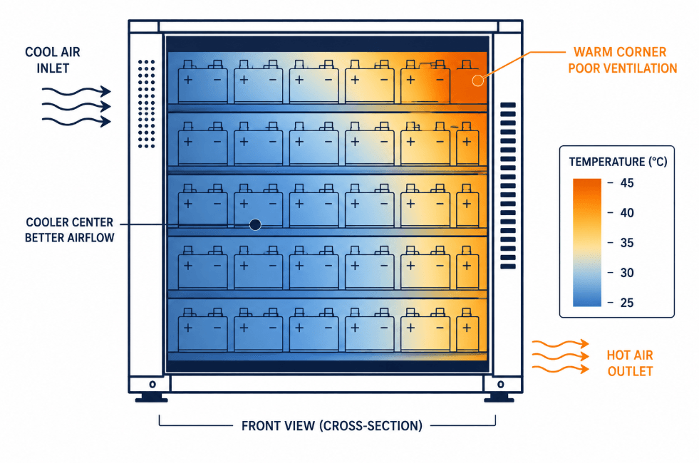
Thermal design is the first lever against in-service cell imbalance. It acts before the BMS ever needs to balance anything. For the specific causes of uneven pack temperature — coolant path position, cell position within the rack, and current-path resistance — and the ΔT targets a well-designed system should hit, see our cell temperature gradients guide. The takeaway for imbalance control specifically: any gradient beyond those targets does not just cost efficiency. It feeds directly into the heat-aging-resistance loop above, and the wider the gradient, the faster the affected cells pull away from the rest of the pack.
Design Around the Worst Case, Not the Average
A common mistake sizes cooling around the pack’s average temperature. Average temperature can look fine. Meanwhile, individual cells can sit well outside it. Measure the worst-case gradient across the pack instead of the mean. Design cooling around that number. This resistance rise is the same mechanism covered in our cell internal resistance guide. A pack running meaningfully above those ΔT targets — commonly the case in a poorly ventilated rack corner — is exactly the failure mode that accelerates in-service cell imbalance in the affected cells, over a multi-year service life.
Choosing a Balancing Topology for the Cycling Profile
Balancing topology is the second lever. Passive balancing bleeds excess energy off higher-SOC cells as heat. It is simple and low-cost. It works fine for light daily cycling with well-matched cells. But passive current is small. It is often just tens to a few hundred milliamps. It cannot keep pace with fast-building imbalance under heavy cycling or a strong thermal gradient.
| Feature | Passive Balancing | Active Balancing |
| Typical current | Tens to a few hundred mA | 1–5A |
| Cost | Low | Higher, more hardware |
| Best fit | Light daily cycling, well-matched cells | Heavy cycling, thermal gradients, long-duration assets |
| Energy handling | Bleeds excess as heat | Moves energy between cells |
| Effect on in-service cell imbalance | Slows drift on light-use systems | Keeps pace with faster-building drift |
When Active Balancing Earns Its Cost Against In-Service Cell Imbalance
Active balancing moves energy between cells instead of burning it off. It corrects gaps far faster, at one to several amps. This higher cost pays off in three cases. First, systems that cycle more than once daily, since imbalance gets less rest time between corrections. Second, systems with a thermal gradient that design alone cannot remove — the same resistance growth this drives also affects cutoff timing; see our DCIR-adaptive cutoff guide. Third, long-duration systems built for fifteen years or more, where small ongoing gains add up to real lifetime value.
Linking Imbalance Back to SOC Estimation
In-service cell imbalance and SOC estimation accuracy feed each other. A design that treats them as separate problems will underperform. A biased SOC estimate can send the balancer a false signal. It might correct a gap that is not really there. Or it might miss one that is. This is the same shared-state problem seen in EKF SOC estimation design. The balancer and the estimator both need one current, shared view of each cell. They should not run on two readings that can quietly disagree.
Setting a Practical Alert Threshold
A voltage spread over 50 to 100 millivolts across cells is a common alert threshold on LFP. The chemistry’s flat curve means even a real SOC gap may show only a small voltage difference. Log these events instead of reacting to one reading. A single high-current moment can cause a spread that resolves on its own.
Key Takeaways
In-service cell imbalance differs from factory cell matching. It is driven mainly by heat, and the aging that heat speeds up. Thermal layout is the first line of defense, especially sizing cooling around worst-case gradients, not pack averages. Balancing topology should match the cycling profile. Passive balancing suits light daily cycling. Active balancing earns its cost in heavy-cycling, high-gradient, or long-duration systems. Imbalance control and SOC estimation should share state, not run as separate systems, since each one affects the accuracy of the other.
Frequently Asked Questions
What causes in-service cell imbalance if the pack started well matched?
Uneven pack temperature is the main driver. Hotter cells age faster and gain resistance faster. That raises sag under load, which can push the cell hotter still. The gap compounds over years of cycling.
Does active balancing fix a pack that started out mismatched?
No. Active balancing corrects ongoing in-service cell imbalance much faster than passive balancing. But neither approach can create capacity a weak cell never had. A bad starting mismatch still needs fixing at the cell-matching stage, before assembly.
What voltage spread signals a real in-service cell imbalance problem on LFP?
A spread over 50 to 100 millivolts is a common threshold worth checking. Still, the trend across cycles matters more than any single reading.
Further Reading
Cell Matching Before Pack Assembly
BMS for LiFePO4 Batteries: Requirements and Parameters
Cell Internal Resistance: What It Is and How to Measure It
Cell Temperature Gradients in BESS: Safe ΔT Limits and What Causes Uneven Heating








Trackbacks & Pingbacks
[…] In-Service Cell Imbalance in LFP BESS […]
[…] In-Service Cell Imbalance guide covers when passive balancing is good enough, and when active balancing earns its extra […]
Leave a Reply
Want to join the discussion?Feel free to contribute!