
Fault Ride-Through Features: The PCS Hardware and Control Functions Behind LVRT/HVRT Compliance
Fault ride-through features are what actually turn a grid-code curve into real PCS behavior during a fault. A ride-through curve on a datasheet is a target, not a mechanism — the hardware and control functions inside the PCS are what determine whether a unit actually meets that target when a real fault hits the line. This article breaks down what those fault ride-through features are and how they work together, from gate-driver-level protection up through plant-level coordination.
| Quick Answer Fault ride-through features are the hardware and control functions inside a PCS — current limiting, DC-link protection, and DC-side energy absorption — that let it meet a grid-code ride-through curve. A compliant curve on a datasheet doesn’t say which of these features a PCS actually implements. |
Our guide to LVRT and HVRT ride-through covers the grid codes and voltage-against-time curves that compliance is measured against. This article goes one level deeper and walks through the specific hardware and control features inside the PCS that make ride-through possible in the first place. Two PCS units can both carry a compliant ride-through curve on their datasheets. They can still behave very differently under an actual fault, because the curve describes an outcome, not an implementation.
Two Layers of Fault Ride-Through Response
A PCS handles a fault in two layers. The layers operate on very different timescales. Both layers have to work correctly, or fault ride-through features never get the chance to activate.
- Hardware-level protection reacts in microseconds to low milliseconds. Its only job is to keep the semiconductors from destroying themselves. It has no concept of a grid code.
- Control-level ride-through reacts over tens to hundreds of milliseconds. This layer decides whether the PCS stays connected, injects reactive current, and follows the shape of the required curve.
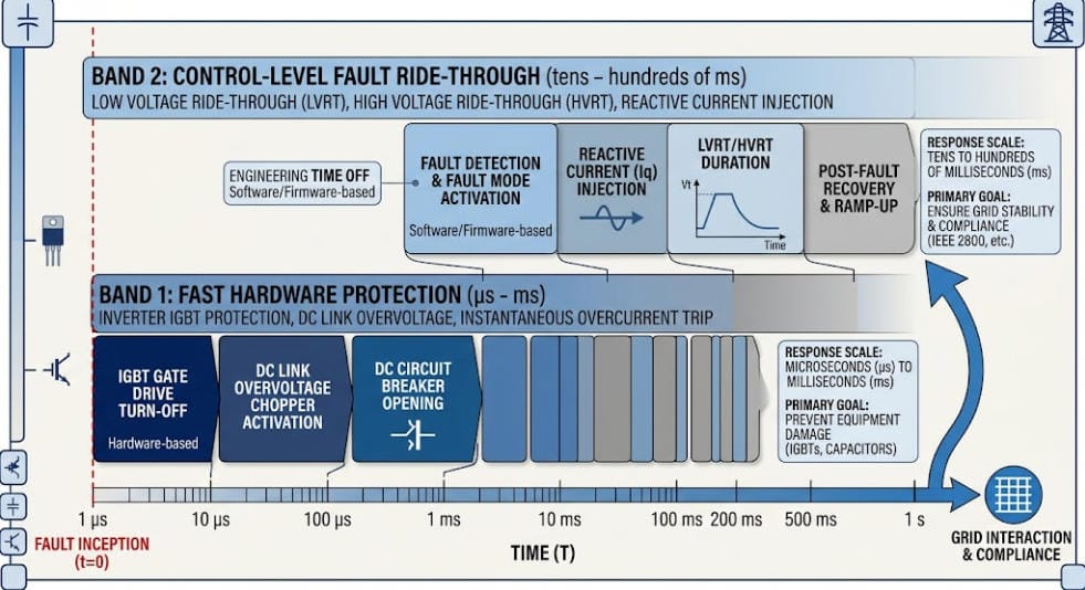
If the hardware layer trips protectively, the control layer never gets the chance to ride through anything. Whichever layer is more conservative sets the PCS’s real fault ride-through capability — not the control algorithm alone.
Hardware-Level Fault Ride-Through Features
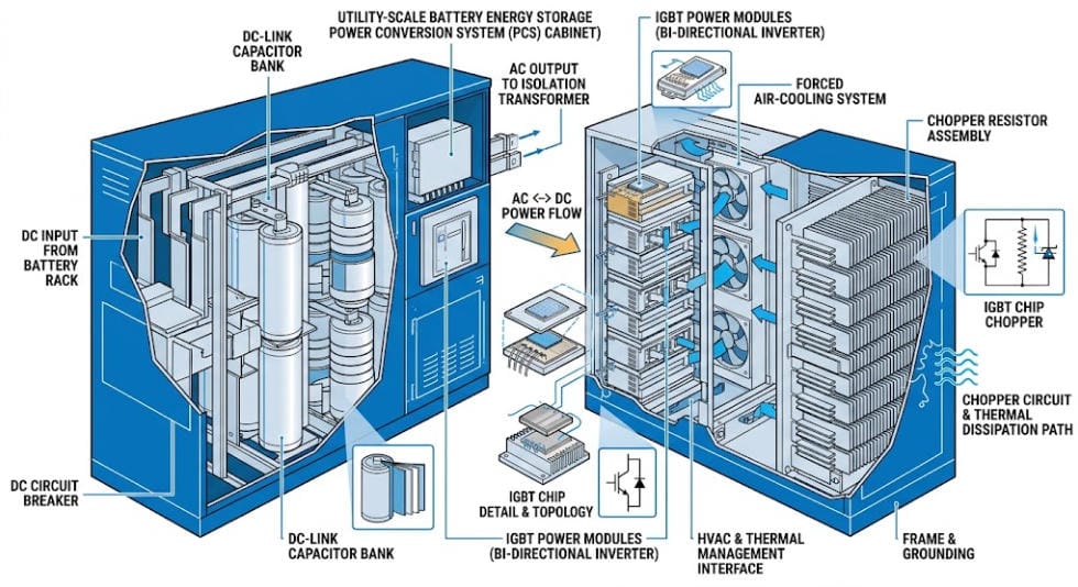
The fastest protection in a PCS sits at the gate-driver level. It senses the collector-emitter voltage of each IGBT to detect desaturation, a condition that signals an output short or a failing device. Engineers tune desaturation-sensing circuits deliberately to avoid nuisance tripping during normal switching transients. The circuits still have to catch a genuine fault fast enough to protect the device.
DC-Link Overvoltage Protection Features
Fault ride-through duty puts stress on the DC side, not just the AC side. During a grid voltage swell, or when active power suddenly can’t be exported at the pre-fault rate, energy backs up into the DC-link capacitor. Left unmanaged, this drives DC-link voltage past the semiconductors’ safe operating limit. The standard hardware answer is a brake chopper: a switch and resistor in series across the DC bus. The chopper circuit compares DC-link voltage against a threshold and switches accordingly, so it dumps excess energy as heat only when the bus voltage would otherwise exceed its saturation limit. Well-designed implementations fire the chopper only when needed. That way, the system wastes no energy during a swell the DC side can absorb on its own.
The wider category of hardware fault ride-through features for DC-link protection includes DC chopper resistors, dynamic braking resistors, and, in some designs, superconducting or bridge-type fault current limiters. These originated in wind turbine converters. The underlying function — dumping fault-driven excess energy somewhere the semiconductors can tolerate — applies directly to PCS design for solar and BESS.
Chopper sizing matters beyond a single event. A resistor sized to survive one fault safely can still overheat if the plant experiences repeated faults in close succession. Repeated faults are common on weak or fault-prone feeders. Duty-cycle rating, not just peak wattage, is the number to check when specifying the chopper.
Control-Level Fault Ride-Through Features
Once the hardware layer confirms the fault is survivable, the control layer decides how the PCS behaves for the rest of the ride-through window. This matters most for grid-forming PCS designs. Utility-scale BESS increasingly uses grid-forming designs because they set their own voltage reference rather than tracking the grid through a phase-locked loop. Three main control-level fault ride-through features keep grid-forming output current within hardware limits during a fault:
- Current saturation: the controller switches into a current-controlled mode and fixes the current reference at the PCS’s maximum rated output for the duration of the fault.
- Virtual impedance: the controller inserts an artificial impedance into its internal voltage-reference calculation. This lowers the commanded voltage in proportion to output current and limits current without a hard mode switch.
- Priority-based saturation: a blended approach that combines current saturation and virtual impedance. It captures the current-limiting reliability of the first method with the smoother, more predictable transient response of the second.
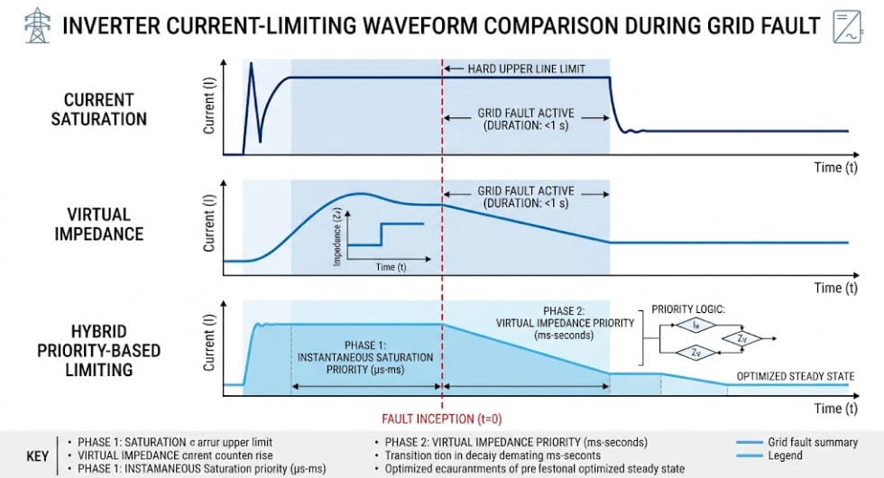
These three approaches trade off differently. Engineers can tune virtual-impedance methods to output more reactive power during the fault than a plain current-limiting approach, which improves voltage support at the point of connection. That only works if they tune the virtual impedance gain correctly. A gain value that’s too small fails to limit current under a severe sag. A gain that’s too large can trigger instability. Published tuning work generally lands on a gain factor between roughly 5 and 10 to balance decoupling and damping.
Timing the virtual impedance is its own design problem. Too little virtual impedance risks depleting the DC bus; too much can cause a grid-forming unit to lose synchronism with other units on the same plant. That risk becomes real once a plant has more than one grid-forming PCS responding to the same event independently.
Fault Ride-Through Features for Unbalanced (Asymmetrical) Faults
Most faults on a distribution or sub-transmission feeder are unbalanced — single-line-to-ground or line-to-line — not the symmetrical three-phase dip used in headline grid-code curves. Unbalanced faults introduce negative-sequence voltage and current components. A control loop built only for positive-sequence quantities can’t regulate these components correctly. Some grid-forming control architectures address this by working directly in the stationary reference frame rather than the conventional rotating (synchronous) frame. This design choice simplifies separating and limiting positive- and negative-sequence fault current independently. Engineers make this control-architecture decision well before a fault occurs — a plant controller can’t add it after the fact.
Fault Ride-Through Features That Differ Between BESS and Solar-Only PCS
A solar PCS has one energy source: whatever the array produces at that instant. It can curtail that output but not absorb energy. A BESS PCS has a battery on the DC side that can actively source or sink energy. That difference changes what fault ride-through features can actually do in practice.
- During a voltage swell (HVRT), a BESS can charge from the surplus DC-side energy instead of dumping it through a brake chopper — but only if the BMS accepts a fast charge-current step, not just a steady-state charge-power limit.
- State of charge and cell temperature set the real headroom. Near full SOC or at temperature extremes, the BMS derates charge current. That derating shrinks how much of a voltage swell the battery can absorb and pushes the PCS back toward reactive-current absorption or a supplemental dump resistor.
- This means the PCS-BMS communication interface needs a fast current-limit path for ride-through events. That path has to run faster than the slower power-limit updates the system uses during normal charge/discharge scheduling.
None of this shows up on a PCS current-vs-time datasheet curve, because the curve is a converter-side spec. Whether the battery can actually support that curve under real SOC and temperature conditions is a system-level integration question, not a spec-sheet question.
Converter Topology and Fault Ride-Through Behavior
Topology choice shapes how fault current is distributed and controlled inside the converter itself.
- Two-level converters concentrate fault current stress on fewer semiconductor devices per phase leg. This simplifies control but raises per-device stress during a fault.
- Multilevel topologies (such as neutral-point-clamped or modular multilevel designs) spread that stress across more devices. They allow finer control of output voltage during unbalanced current injection, at the cost of more complex coordinated current-limiting logic across levels.
Plant-level topology matters too. Whether the site uses a string architecture or a small number of centralized PCS units changes how individual-unit current limits sum to the plant’s response at the point of interconnection. See our String vs. Centralized BESS PCS comparison for how that choice plays out beyond fault ride-through behavior.
Plant Controller Coordination for Fault Ride-Through Features
A single PCS unit’s current-limiting response is only half the picture. On a multi-inverter plant, the plant controller must aggregate every unit’s local response into a combined output at the point of interconnection (POI). That combined output has to match the required curve. Individual units sometimes apply current limiting independently, with slightly different thresholds or timing. When that happens, the combined POI response can differ meaningfully from what any single unit’s test report shows. Communication latency between the plant controller and individual PCS units becomes a real design constraint here. Ride-through windows can run as short as tens of milliseconds — too short for a slow polling cycle to matter.
Specifying Fault Ride-Through Features When Selecting a PCS
Treat fault ride-through features as a checklist to verify individually, not a single line item to take on faith.
- Ask which current-limiting algorithm the PCS implements — current saturation, virtual impedance, or a priority-based blend — and how the manufacturer tuned the gain or setpoint, not just whether it claims a compliant curve.
- Ask whether the manufacturer validated the DC chopper or dump resistor for repeated, closely spaced faults, not a single worst-case event.
- Confirm the BMS charge-current step response time. Check whether it’s fast enough to support the PCS’s intended DC-side energy-absorption strategy during HVRT.
- Confirm whether the unit is grid-following or grid-forming, and how its behavior changes during any momentary-cessation window.
- Request fault-current test evidence at the plant-controller level, aggregating multiple units, not only single-unit type-test results.
Key Fault Ride-Through Features at a Glance
| Feature | Why It Matters |
|---|---|
| Gate-driver desaturation detection | Fastest layer of protection; determines whether the control layer ever gets to ride through the fault |
| DC chopper / dump resistor | Keeps DC-link voltage within limits during a swell; duty-cycle rating matters more than peak wattage |
| Current saturation vs. virtual impedance vs. priority-based | Different trade-offs between reliability, reactive support, and transient smoothness |
| Positive/negative-sequence current control | Required for the unbalanced faults that dominate real-world fault statistics |
| BESS DC-side energy absorption | Lets a BESS actively soak up swell energy instead of only dissipating it — subject to SOC and thermal derating |
| Plant controller aggregation | Individual-unit compliance doesn’t guarantee POI-level compliance on a multi-inverter plant |
Frequently Asked Questions About Fault Ride-Through Features
What’s the difference between hardware-level and control-level fault ride-through features?
Hardware-level features, such as IGBT desaturation detection, react in microseconds to protect the semiconductors. They have no awareness of grid-code requirements. Control-level ride-through features operate over tens to hundreds of milliseconds. This layer actually follows the required voltage-against-time curve. Hardware protection takes priority whenever the two layers conflict.
Why does a BESS have an advantage over a solar-only plant during HVRT?
A BESS can actively charge its battery to absorb surplus DC-side energy during a voltage swell. A solar-only PCS can’t do this — it has no equivalent energy sink beyond curtailing the array.
What is virtual impedance current limiting?
It’s a control technique where the inverter’s controller inserts an artificial impedance term into its internal voltage-reference calculation. This lowers the commanded output voltage in proportion to current and limits fault current without switching the converter into a different control mode.
Do all grid-forming inverters use the same fault ride-through features?
No. Implementations vary in whether they use current saturation, virtual impedance, or a priority-based combination. They also vary in whether they regulate unbalanced fault current in the stationary or synchronous reference frame. These are architecture-level decisions, not settings a plant operator can change after the PCS is built.
Why does DC chopper sizing matter beyond a single fault event?
A brake chopper resistor sized for a single worst-case fault can still overheat if the plant experiences repeated faults in a short period. Repeated faults are common on weaker feeders. Duty-cycle rating, not just peak wattage, determines whether the chopper survives real-world fault patterns.
Further Reading
LVRT and HVRT: Voltage Ride-Through for BESS and Solar
BESS PCS Functions and Features
String vs. Centralized BESS PCS








Trackbacks & Pingbacks
[…] Understand PCS fault ride-through and LVRT/HVRT capability (Fault Ride-Through Features: The PCS Hardware and Control Functions Behind LVRT/HVRT Compliance) […]
[…] compliant curve on a datasheet only states the target. Our Fault Ride-Through Features guide goes a level deeper into the PCS hardware and control functions, like current limiting and DC-link […]
[…] Fault Ride-Through Features in PCS Hardware & Control […]
[…] Fault Ride-Through Features: The PCS Hardware and Control Functions Behind LVRT/HVRT Compliance […]
[…] Fault Ride-Through Features: The PCS Hardware and Control Functions Behind LVRT/HVRT Compliance […]
Leave a Reply
Want to join the discussion?Feel free to contribute!