How to Replace a Diesel Generator with BESS: Sizing, Costs, and Case Studies
How to Replace a Diesel Generator with BESS: Sizing, Costs, and Case Studies
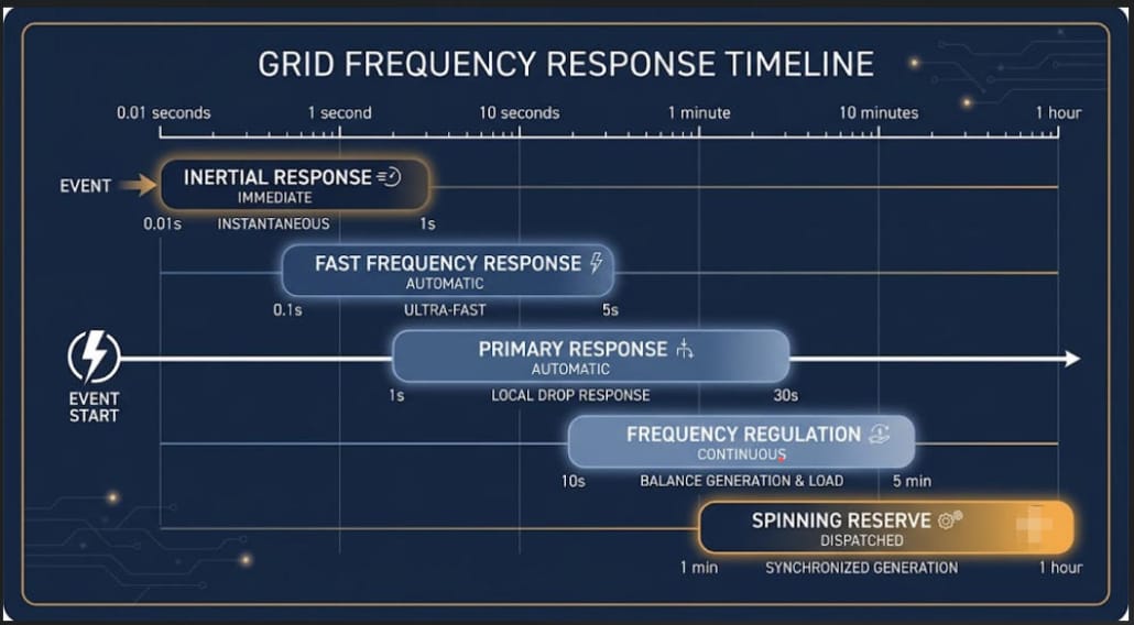
| Quick answer Diesel generator replacement with BESS works in three steps. First, convert your generator’s kVA rating to real kW using the power factor. Second, size the battery in kWh to your load and backup hours. Third, size the PCS in kW to your peak power, with a margin for inrush. A well-sized system cuts daily fuel cost. It switches in under 20 milliseconds, not 10-30 seconds. Most projects pay back in 4 to 7 years. |
For most commercial and industrial (C&I) sites, diesel generator replacement is not a fringe idea anymore. So it is now a normal line item in capital planning.
Diesel gensets are reliable. But they cost money every hour they run, and they need constant upkeep.
A BESS closes that gap in three ways. First, it starts delivering power in milliseconds. Second, it has no moving parts to wear out. Third, when paired with solar, it can cut fuel use close to zero.
This guide covers the real costs, the sizing math, and the kVA-to-kW conversion your generator needs. Also, it covers PCS choice, four case studies, and a free sizing calculator you can add to this post.
Why Facilities Are Pursuing Diesel Generator Replacement in 2026
Three main pressures are pushing facilities away from diesel power. First, fuel prices remain high and unpredictable. Second, engines with hundreds of moving mechanical parts require constant upkeep. Third, ESG regulations are becoming increasingly strict.
While none of these factors are entirely new, LFP battery costs have dropped significantly in recent years. Consequently, the financial math for generator replacement now works for far more commercial and industrial sites than ever before.
The True Cost of Diesel Generator Replacement
Fuel is the biggest cost of running a generator. Also, it scales with load. For example, a diesel generator burns about 0.07 to 0.08 gallons per kWh at 70-80% load.
A 100 kW generator at 75% load burns about $402 a day in fuel alone. That is about $0.22 per kWh. Also, this does not include oil, filters, or testing costs.
Once labor and parts are added, costs climb further. All-in costs often land between $0.35 and $0.65 per kWh, per 2026 generator operating-cost benchmarking.
Costs climb even more at partial load. In fact, generators run least efficiently below 40% load. That is where most backup units sit most of the time.
Maintenance and Wet-Stacking Problems
Because generators are complex mechanical systems, internal parts like pistons and valves naturally wear down over time. Therefore, they demand regular, costly service intervals.
Additionally, running generators at light loads leads to wet-stacking, which occurs when unburned fuel accumulates inside the exhaust system. As a result, the engine suffers accelerated wear and requires even more maintenance.
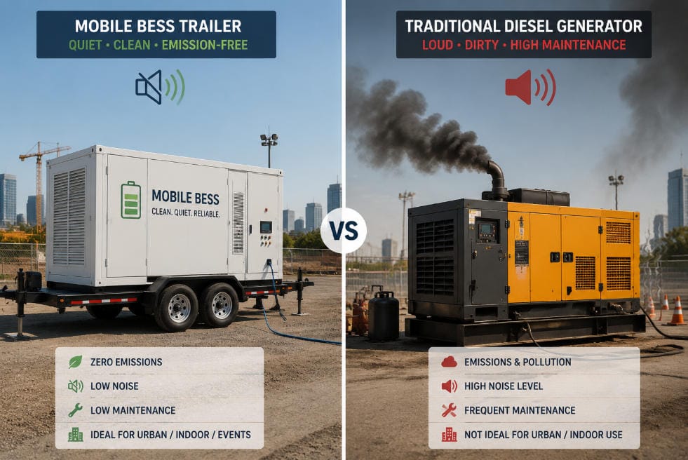
In contrast, a BESS has no moving mechanical components; consequently, it requires almost no scheduled maintenance beyond routine inspection checks.
Emissions and ESG Pressure
Because diesel exhaust releases high amounts of NOx, particulate soot, and $\text{CO}_2$, these emissions increasingly trigger warnings on environmental audits and insurance reviews.
However, a BESS creates zero on-site emissions during operation. Furthermore, when paired with a local solar array, overall facility emissions fall close to zero.
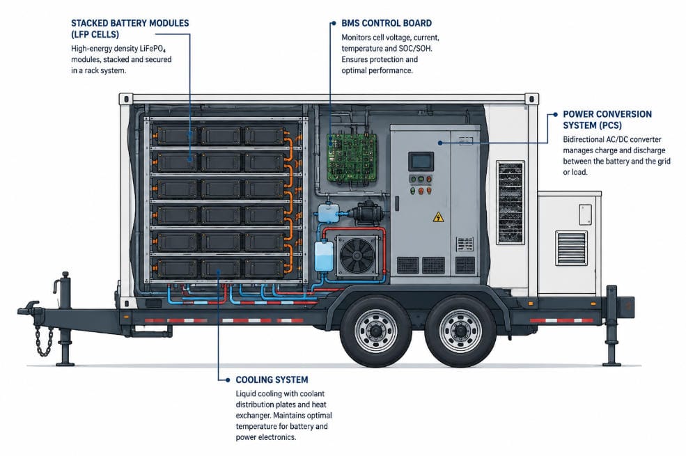
Generator kVA, BESS kWh, and PCS kW: Why the Units Are Different
Here is a detail that trips up many buyers. Generators are rated in kVA, not kW. That is apparent power, not real power.
BESS energy is rated in kWh. Also, PCS power is rated in kW. So these three units are not the same.
Mixing them up can badly oversize, or worse, undersize your system. So convert your generator’s rating to real kW first.
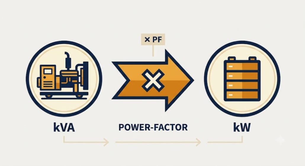
Converting Generator kVA to kW
| kVA to kW Conversion Formula kW = kVA × Power Factor (PF) Industrial loads typically use a default PF of 0.8 unless your generator nameplate or a recent load study states otherwise. |
For example, a 125 kVA generator running at a 0.8 power factor delivers 100 kW of real output (125 x 0.8 = 100 kW). Similarly, a 500 kVA generator at 0.85 power factor yields 425 kW of real power.
Therefore, you must always verify the actual power factor on your generator’s data sheet before sizing your battery system. Otherwise, a single inaccurate assumption will skew all subsequent calculations
Why BESS Uses kWh and PCS Uses kW
A BESS is sized in two distinct steps. First, energy capacity is measured in kWh to determine duration. Second, inverter capacity is measured in kW to handle the load.
Because energy sets runtime while power determines peak instantaneous capacity, confusing these two units often leads to costly site undersizing.
The table below keeps the three units straight.
| Component | Unit | What It Measures |
|---|---|---|
| Diesel generator | kVA (apparent power) | Nameplate rating before power factor is applied |
| Real generator output | kW (real power) | kVA x power factor, the number you actually size around |
| BESS battery | kWh (energy) | How much energy is stored, and how long it can run the load |
| PCS / inverter | kW (power) | How much power it can deliver at any single instant |
Cost Comparison: Diesel Generator Replacement vs. Keeping Your Genset
The table below compares the two options side by side.
| Factor | Diesel Generator | BESS |
|---|---|---|
| Switching time | 10-30 seconds (ATS transfer delay) | Under 20 milliseconds |
| Running cost | $0.22-0.28/kWh fuel at optimal load; $0.35-0.65/kWh all-in | No fuel cost; O&M is largely software-managed |
| Maintenance | Oil, filters, load-bank testing, overhauls | Minimal, no moving parts |
| Emissions | NOx, particulates, CO2 on every run | Zero on-site emissions |
| Fuel logistics | Needs on-site storage and refueling | None |
| Noise | 65-85 dBA typical | Near-silent |
| Typical payback | Not applicable, an ongoing operating cost | 4-7 years via avoided fuel and demand charges |
Most sites do not remove the generator on day one. Instead, they install the BESS first, right alongside the running genset.
The PWRNXT diesel generator replacement program in India uses this same model. So do similar C&I projects elsewhere.
Next, the team tests switching performance on-site. Only then does the generator get downgraded to backup, or retired.
How to Size a BESS for Diesel Generator Replacement
Sizing a BESS depends on two primary metrics: energy (kWh) and power (kW). If you balance this ratio correctly, the system operates seamlessly.
However, if you miscalculate, the battery will either trip under heavy loads or unnecessarily inflate project costs.
Step 1 — Determine Your Critical Load in kW
Pull 12 months of interval data. Or, run a load study during a real outage.
If you only have kVA, convert it to kW first, using the formula above. Then use the load you actually want to keep on.
Full production and critical-circuits-only are very different numbers. So pick the right one upfront.
Step 2 — Determine Required Backup Hours
Base this on real outage history, not a guess. Instead, pull it from utility data or your own outage log.
Weak grids with short, frequent outages need a shorter, high-cycling BESS. Grids with rare but long outages, by contrast, need more stored energy per kW.
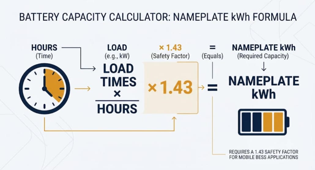
Step 3 — Calculate Nameplate Capacity for Diesel Generator Replacement
The baseline formula is shown below.
| BESS sizing formula Usable Energy Required (kWh) = Critical Load (kW) x Backup Duration (hours) Nameplate Capacity (kWh) = Usable Energy Required x 1.2 safety margin / (Depth of Discharge x Round-Trip Efficiency) For LFP at 90% DoD and about 93% round-trip efficiency, this simplifies to: Nameplate Capacity (kWh) = Critical Load (kW) x Backup Duration (hours) x 1.43 |
The 1.2x margin covers load growth and inrush. The DoD and efficiency terms cover two more losses.
First, the energy a lithium battery cannot safely use. Second, conversion losses across the inverter and BMS.
Step 4 — Worked Examples
Here are three quick examples. Each one starts from a real kW figure, already converted from kVA.
- 50 kW load, 4-hour backup target: 50 x 4 x 1.43 ≈ 286 kWh nameplate capacity
- 100 kW load, 8-hour backup target: 100 x 8 x 1.43 ≈ 1,147 kWh, about 1.15 MWh
- 250 kW load, 2-hour bridge-power target: 250 x 2 x 1.43 ≈ 717 kWh
BESS Sizing Reference Table for Diesel Generator Replacement
Use this table for early budget sizing. Always confirm with a real load study first.
| Critical Load | 2-Hour Backup | 4-Hour Backup | 8-Hour Backup |
|---|---|---|---|
| 25 kW | 72 kWh | 143 kWh | 287 kWh |
| 50 kW | 143 kWh | 287 kWh | 574 kWh |
| 100 kW | 287 kWh | 574 kWh | 1,147 kWh |
| 250 kW | 717 kWh | 1,434 kWh | 2,868 kWh |
| 500 kW | 1,434 kWh | 2,868 kWh | 5,736 kWh |
PCS and Inverter Sizing for Diesel Generator Replacement
Battery kWh and PCS kW get sized separately. Mixing them up is a costly mistake in BESS procurement.
As Sunlith’s BESS C-rate guide explains, size the PCS first, to the peak power you need. Then size the battery for the required duration.
Otherwise, a big battery behind a small PCS still cannot deliver full power. So the PCS becomes the real bottleneck, no matter how much energy sits in the racks.
PCS Power Rating: Add an Inrush Margin
Motors, compressors, and heavy HVAC units draw large surge currents during startup. Therefore, a standard sizing protocol adds a 1.25x margin over steady-state peak load.
However, for facilities operating heavy direct-on-line (DOL) motors, initial surge spikes can briefly reach 3x to 6x running current. As a result, you should round your final power rating up to the next standard PCS capacity tier.
Then round this up to the next standard PCS size. Most PCS units come in 50-500 kW steps.
| Critical Load | PCS Rating (1.25x margin) | Approx. C-Rate at Rated kWh |
|---|---|---|
| 50 kW | 75 kW | 0.26C, matches 4-hr duration |
| 100 kW | 125 kW | 0.11C, matches 8-hr duration |
| 250 kW | 350 kW | 0.49C, matches 2-hr duration |
C-Rate and Discharge Duration
C-rate compares PCS power to battery energy. A 0.5C system runs at full power for 2 hours.
A 1C system, by contrast, runs for 1 hour instead. It also costs 20-40% more, since it needs bigger power electronics.
Past about 1.5C, systems often need liquid cooling too. Most 2-8 hour backup projects land in the 0.1C-0.5C range, which keeps cost down and favors longer cycle life.
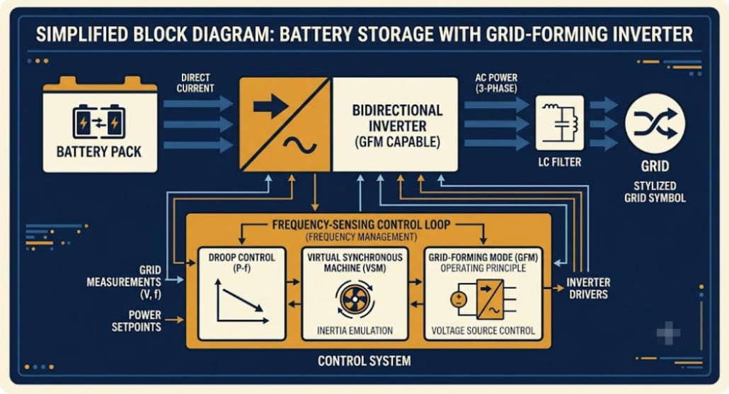
Grid-Forming vs. Grid-Following PCS
A grid-following PCS needs a live voltage signal to sync to. It works for peak shaving, but not for a dead, powered-down site.
So true backup duty needs a grid-forming PCS, or a hybrid inverter with black-start. It must set voltage and frequency itself, the instant power drops.
Diesel Generator Replacement Sizing Calculator
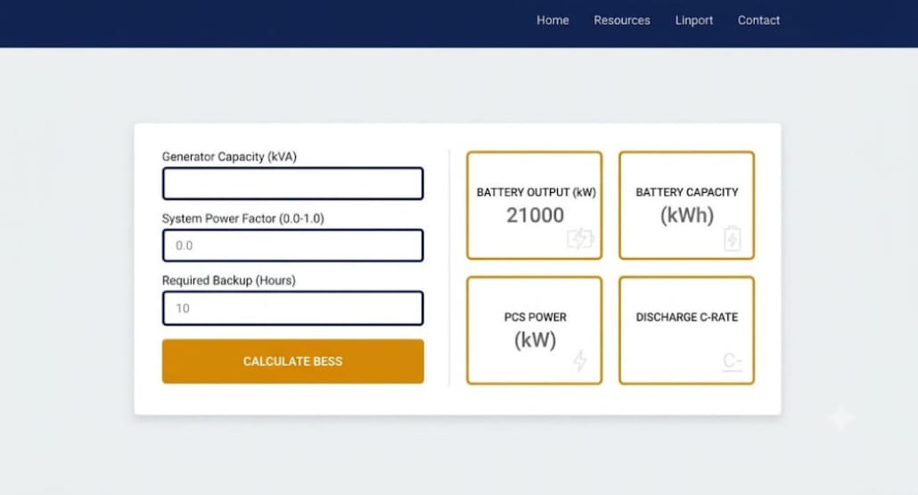
Use the free calculator below to size your site. Enter your generator’s kVA, power factor, and backup hours.
It converts kVA to real kW, then applies the formulas from this guide.
Diesel generator replacement calculator
Enter your generator’s rating and backup needs to get a starting BESS and PCS/inverter size. This is a budgetary estimate — confirm with a load study before procurement.
Advanced settings (DoD, efficiency, margins)
How the Calculator Works
To operate the calculator, simply enter your generator kVA, power factor, optional kW override, and required backup duration.
Additionally, advanced settings allow you to fine-tune depth of discharge, system efficiency, and safety margins.
First, your real load in kW. Second, a suggested BESS size in kWh. Third, a PCS size in kW, rounded to a standard size. Finally, the resulting C-rate.
| Input | Default | Purpose |
|---|---|---|
| Generator kVA | None, required unless using peak load override | Nameplate rating from the generator’s data plate |
| Power factor | 0.8 | Converts kVA to real kW |
| Peak load override (kW) | Blank | Use if you already have a measured kW figure |
| Backup hours needed | None, required | Sets the energy duration target |
| Depth of discharge | 90% | Usable portion of the battery’s rated capacity |
| Round-trip efficiency | 93% | Accounts for conversion losses |
| Energy safety margin | 20% | Buffer for load growth and inrush |
| PCS inrush margin | 25% | Buffer for motor and HVAC startup surge |
Case Studies: Diesel Generator Replacement with BESS in Practice
The examples below come from real 2026 deployments.
For more C&I projects, see Sunlith’s C&I BESS case studies roundup.
Case 1 — Diesel Generator Replacement at an Industrial Plant
An Indian market study covered a plant that kept its diesel generator. Instead, it added a behind-the-meter BESS rather than removing the genset.
So the battery handled daily outages with frequent cycling. The generator, meanwhile, stayed on standby for deeper outages.
A 1-hour BESS, sized to the average outage, paid back faster than a bigger system built for worst-case events. That is a lesson against over-sizing.
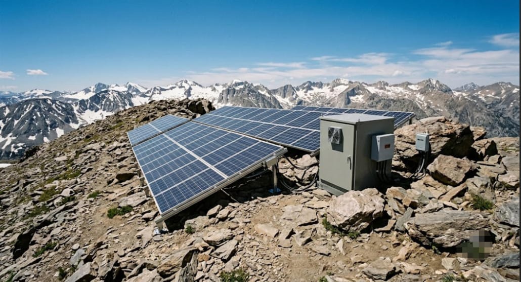
Case 2 — Solar + BESS Replacing Diesel at High Altitude (Leh, India)
Leh is a remote, high-altitude region of India. But it has long relied on diesel for backup power.
There, solar-plus-storage was rolled out to replace diesel at scale. The same study found this works even off-grid, once local power prices rise even a little.
This matches the pattern in Sunlith’s Island Grid BESS engineering guide. There, solar takes over as the main power source, and the BESS covers stability and overnight load.
Case 3 — Diesel Generator Replacement for a Telecom Tower Network
A telecom operator ran diesel gensets across remote towers. As a result, this meant high fuel bills and constant upkeep.
So the company switched to solar-plus-battery as the main power source at each site. Generators stayed on as backup only.
Fuel use dropped a lot. As a result, generator runtime fell, service intervals stretched out, and uptime improved.
Case 4 — Hospital Hybrid Backup (Australia)
A hospital in Australia added a BESS next to its diesel generators. Instead, it did not remove them.
This fits any site where power loss is a safety risk. The hybrid setup cut daily fuel use and backed up short outages without starting the genset.
How to Transition from Generator to BESS: A Phased Approach
- Audit the load: capture 12 months of interval data, or a representative outage load profile. Also, confirm whether backup covers full production or critical circuits only.
- Size the BESS and PCS independently: use the kWh formula for energy. Then size the PCS to peak kW, with an inrush margin.
- Install alongside the existing generator: commission the BESS in parallel, and do not decommission the genset until performance is proven.
- Run site acceptance testing: verify switching time, SLA compliance, and grid-forming black-start behavior under real load.
- Reclassify or retire the generator: once the BESS reliably carries day-to-day backup, shift it to a rarely-used secondary role. Or remove it from service entirely.
Key Takeaways on Diesel Generator Replacement
| Point | Why It Matters |
|---|---|
| Convert kVA to kW before sizing anything | Generators are rated in kVA; BESS kWh and PCS kW both depend on the real kW figure |
| Size energy (kWh) and power (kW) separately | An undersized PCS behind a large battery still fails to carry the load |
| Use Load x Hours x 1.43 as a starting formula | Bakes in a 1.2x safety margin, 90% DoD, and about 93% round-trip efficiency for LFP |
| Diesel costs $0.22-0.65/kWh all-in | Fuel alone runs $0.22-0.28/kWh at optimal load; maintenance pushes it higher |
| Grid-forming PCS is required for true backup duty | Grid-following inverters cannot black-start a de-energized site |
| Install BESS alongside the generator first | Every documented case study kept the genset as backup during commissioning |
| Typical payback is 4-7 years | Driven by avoided fuel spend, plus demand charge and peak-shaving revenue |
Frequently Asked Questions
Can a BESS completely replace a diesel generator?
Yes, for many sites. If outages run from minutes to a few hours, a well-sized BESS can fully replace the generator. It just needs a grid-forming PCS.
This also works if solar recharges the battery each day. But sites with life-safety loads, or rare, multi-day outages, often keep a generator as backup.
What is a realistic payback period for diesel generator replacement with BESS?
Most C&I projects pay back in 4 to 7 years. So this comes mainly from avoided fuel and upkeep cost.
It also comes from peak-shaving and demand-charge savings, on normal days with no outage.
Why does PCS sizing matter separately from battery kWh?
Battery kWh sets how long the system runs. PCS kW, by contrast, sets how much power it can push at once.
So an undersized PCS caps output, no matter how much energy sits in the battery.
How do I convert my generator’s kVA rating for BESS sizing?
Multiply the kVA rating by the power factor to get real kW. Most industrial sites run near 0.8 PF.
But check your generator’s data sheet to confirm. For example, 125 kVA at 0.8 PF equals 100 kW.
What battery chemistry works best for diesel generator replacement?
LFP is the standard choice for C&I diesel generator replacement. Also, it offers strong thermal stability and long cycle life.
It also carries no thermal runaway risk, unlike some other lithium types. This is the same reasoning behind Sunlith’s chemistry choice across its C&I line.