How to Deploy Grid-Following BESS Without Costly Failures
What Is BESS Grid-Following?
BESS grid-following is the most widely used inverter control mode in battery storage today. In simple terms, a grid-following (GFL) inverter locks its output to the existing grid voltage and frequency. Because of this, the battery system follows the grid — not the other way around.
This approach works well in most commercial and utility projects. In fact, roughly 85% of all battery storage systems deployed worldwide use grid-following control. Therefore, understanding how it works — and where it has limits — is essential for engineers, developers, and asset owners alike.
This comprehensive guide breaks down everything you need to know. We begin with a deep dive into the technical inner workings of GFL control before comparing it directly to Grid-Forming (GFM) architecture. From there, you will learn about core C&I applications, weak-grid constraints, and critical deployment mistakes to avoid.
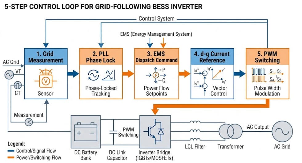
1. How a BESS Grid-Following Inverter Works
A BESS grid-following inverter acts as a controlled current source. Its job is to inject real power (watts) and reactive power (VAR) into the grid. Crucially, it does this at the exact voltage and frequency the grid is already running at.
Here is how the process works, step by step.
Step 1 — Grid Measurement
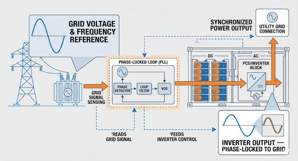
To begin, the inverter measures grid voltage, frequency, and phase angle at the Point of Common Coupling (PCC) thousands of times every second. This continuous tracking ensures the system always maintains a fresh, accurate picture of grid conditions.
Step 2 — Phase Locking via the PLL
A Phase-Locked Loop (PLL) algorithm then processes these measurements to lock the inverter’s internal reference directly to the grid’s phase angle. Consequently, the inverter stays perfectly synchronised even if the grid drifts slightly in frequency or voltage.
Step 3 — Power Dispatch from the EMS
The Energy Management System (EMS) sends a power dispatch command — for example, ‘discharge at 500 kW.’ Following this instruction, the hardware changes the target value into a current reference in the d-q rotating frame.
Step 4 — PWM Switching
High-speed IGBT transistors switch rapidly — typically at 2 to 20 kHz — using Pulse Width Modulation (PWM). As a result, the hardware generates a clean AC output that perfectly matches the reference signal.
Step 5 — Real-Time Feedback Control
Finally, a fast inner current control loop corrects any lingering errors. Running at roughly 1 to 2 kHz, this final safety loop ensures the entire BESS grid-following control cycle completes in under one millisecond.
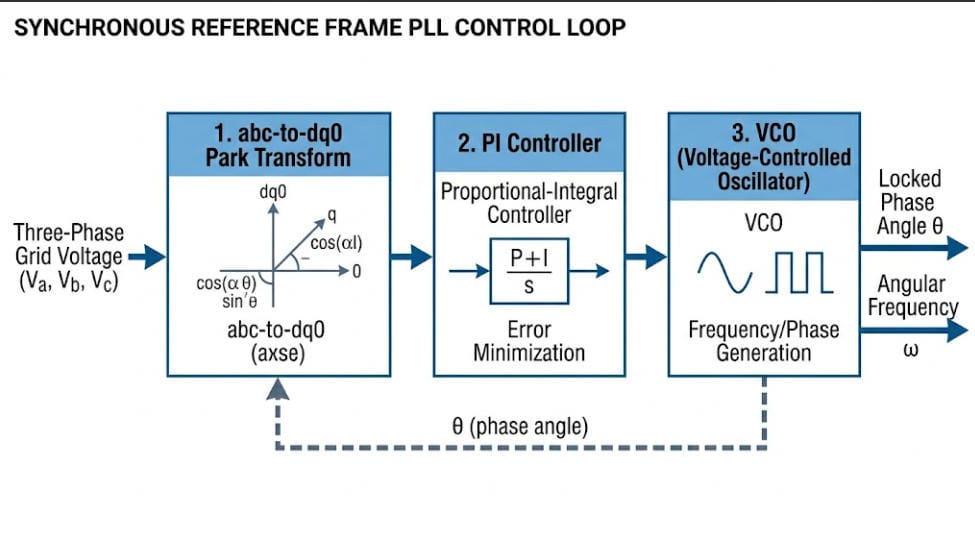
2. The PLL: Why BESS Grid-Following Needs a Strong Grid
The Phase-Locked Loop (PLL) is the core of every GFL system. It is also the source of its main limitation.
The PLL works by comparing the inverter’s internal oscillator to the measured grid frequency. If these two variables drift apart, the algorithm instantly generates a correction signal. Once they match up perfectly, the loop achieves a ‘locked’ state. Modern BESS grid-following inverters use Synchronous Reference Frame PLLs (SRF-PLLs) to handle real-world imperfections — including unbalanced voltages and harmonic distortion.
Key point: The PLL needs a stable grid voltage to lock onto. If the grid voltage collapses, the PLL has no reference. As a result, the GFL inverter cannot maintain output on its own. This is the defining constraint of BESS grid-following technology.
For an alternative approach that removes this constraint, see our article on BESS Grid–Forming Technology.
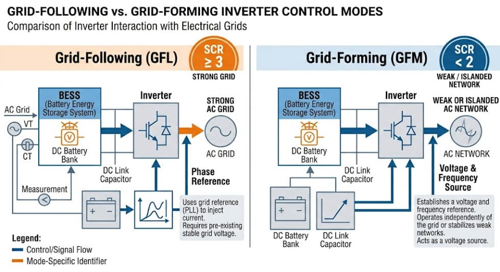
3. BESS Grid-Following vs Grid-Forming: Key Differences
Grid-following and grid-forming are both valid technologies. However, they solve different problems. The table below shows the core differences clearly.
| Attribute | Grid-Following (GFL) | Grid-Forming (GFM) |
|---|---|---|
| Inverter type | Controlled current source | Controlled voltage source |
| Needs grid voltage? | Yes — requires reference signal | No — creates its own reference |
| Black start capable? | No | Yes |
| Islanded operation? | No (without external VSI) | Yes |
| Synthetic inertia | Limited / indirect | Native capability |
| Frequency response speed | Fast (< 500 ms), reactive | Instantaneous (< 20 ms) |
| Cost vs baseline | Baseline cost | ~10–20% premium |
| Min. SCR at PCC | SCR ≥ 3 recommended | Functions at SCR < 1.5 |
| Best for | Strong-grid C&I and utility sites | Weak grids, islands, high-IBR networks |
| Market share (2025) | ~85% of deployed systems | ~15% and growing |
Design rule: The key question is not ‘which is better’ — it is ‘what is the Short Circuit Ratio at your Point of Common Coupling?’ If SCR is 3 or above, BESS grid-following is the right choice. If SCR falls below 2, then Grid-Forming deserves serious consideration.
Related reading: BESS Grid-Forming Technology: The Architecture Stabilising Tomorrow’s Grid
4. Where BESS Grid-Following Excels
BESS grid-following is the right choice for most projects. Below are the applications where it delivers the most value.
4.1 GFL for Peak Shaving and Demand Charge Reduction
This is the most common application for C&I BESS grid-following systems. To lower costs, the EMS monitors real-time facility demand and dispatches battery power right before a peak occurs. Because utility connections are typically stable at industrial sites, the GFL inverter easily maintains a rock-solid phase reference to execute these commands with sub-second precision.
Given that demand charges often make up 30% to 70% of a commercial electricity bill, this single strategy can completely justify the initial BESS investment.
See: How C&I BESS Peak Shaving Lowers Demand Charges
4.2 Arbitrage Opportunities via Time-of-Use Tiers
Grid-following BESS systems are ideal for energy arbitrage. In this strategy, the battery charges during off-peak hours at low tariff rates. Then it discharges during peak windows at high tariff rates. The grid itself provides the stable voltage reference needed for clean energy import and export. As a result, a well-sized GFL system can cut total energy costs by 10 to 25%.
4.3 Ancillary Services and Fast Frequency Response
Modern BESS grid-following inverters respond to frequency deviations in under 200 milliseconds. They detect frequency deviation via the PLL and adjust active power output proportionally — a method called droop-based frequency response. As a result, GFL BESS qualifies for Fast Frequency Response (FFR) and Primary Frequency Response (PFR) markets in most grid codes.
4.4 Smooth Integration for Solar and Wind Power
Renewable generation assets almost always use GFL inverters for their battery pairings. In these setups, the solar PV inverter acts as the primary grid interface while the BESS operates in parallel to absorb surplus generation. This combination fills sudden production drops to give the facility a smooth, consistent power supply.
See: How C&I BESS Enhances Solar and Wind Power Integration
4.5 Capacity Markets and Spinning Reserves
Utility-scale projects can participate directly in regional capacity markets by providing committed megawatts of fast-responding backup generation. Because a battery can earn fixed capacity payments while executing daily arbitrage, this stacked revenue structure dramatically improves project economics.
5. BESS Grid-Following Limitations to Plan For
No technology is without constraints. Failing to understand these leads to underperforming systems and costly redesigns. Here are the four main limitations of BESS grid-following systems.
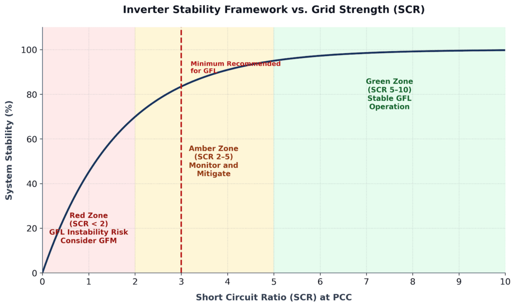
5.1 GFL Performance in Weak Grids (Low SCR)
As the Short Circuit Ratio (SCR) drops below 3, GFL inverters face severe stability challenges. When operating below an SCR of 1.5, multiple parallel units can easily trigger sub-synchronous oscillations. This interaction creates a significant operational risk for remote industrial sites, isolated microgrids, and networks with heavy inverter-based resource (IBR) penetration.
The IEEE Standard 2800-2022 directly addresses these network challenges. If your target site features an SCR below 3, executing a detailed grid stability study is a mandatory step before specifying any GFL hardware.
5.2 Total Black-Start Limitations
An islanded or dead grid cannot be energised by standard GFL hardware. Because it requires an active voltage wave to lock onto, a grid-following system cannot serve as your lone backup source during a total utility outage. To achieve complete independence, you must pair the battery with a diesel generator, a fuel cell, or a Grid-Forming inverter.
For C&I sites with a critical backup requirement, the Static Transfer Switch (STS) becomes an essential design element. We explain how below.
5.3 Microgrid Constraints Without Synchronous Reference
For isolated microgrids — remote mining camps, island grids, or off-grid industrial sites — a GFL-only BESS cannot function once grid connection is lost. In that case, a Grid-Forming inverter or a synchronous generator must hold the local voltage and frequency reference.
5.4 Control Loop Vulnerabilities During System Faults
During a severe voltage disturbance, the grid voltage drops sharply. As a result, the PLL can momentarily lose synchronisation. Modern inverters have Fault Ride-Through (FRT) algorithms to prevent tripping during these events. However, poorly tuned PLLs remain a source of nuisance trips in the field.
Key standards that govern FRT requirements include ENTSO-E Network Code RfG (Europe) and IEEE 1547-2018 (USA).
6. BESS Grid-Following in C&I Projects: Value Stacking
For commercial and industrial customers, a BESS grid-following system is almost always the starting point. A well-designed system combines multiple value streams at once — a practice called value stacking. The table below shows how each stream works together.
| Value Stream | Typical Annual Impact | How GFL Enables It |
|---|---|---|
| Peak Shaving | 20–40% demand charge reduction | Discharges at demand spike with sub-second precision |
| TOU Arbitrage | 10–25% energy cost reduction | Charges off-peak, discharges at peak tariff windows |
| Backup Power (with STS) | Zero downtime for critical loads | STS transfers load to BESS in under 8 ms on fault |
| FFR / Grid Services | Additional utility revenue | PLL detects frequency deviation; responds within 200 ms |
| Solar Self-Consumption | 15–30% more PV utilisation | Absorbs surplus solar; discharges when PV output falls |
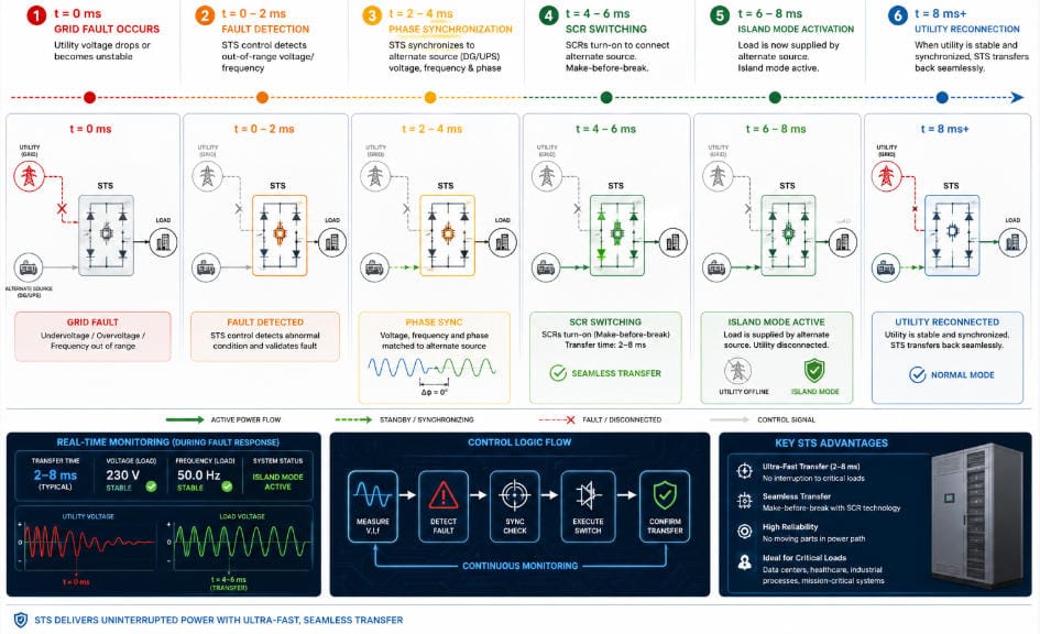
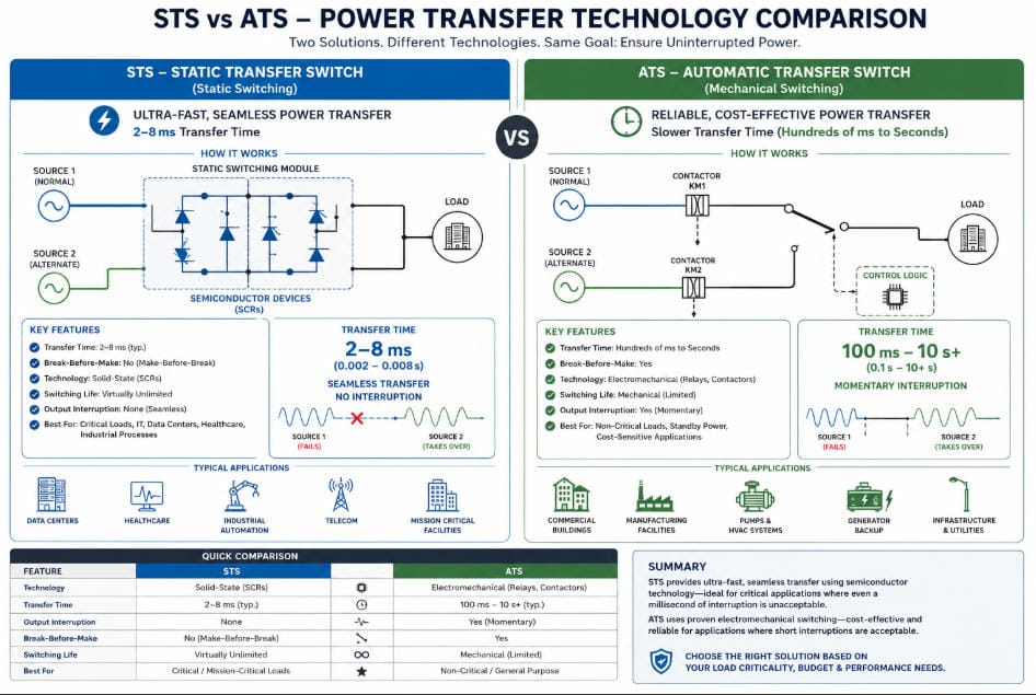
Backup Power: How GFL Works With an STS
A common misconception is that BESS grid-following cannot provide backup power. This is only partly true. When paired with a properly integrated Static Transfer Switch (STS), a GFL system can deliver seamless uninterruptible power to critical loads.
Here is why it works. The STS monitors grid voltage at millisecond resolution. When it detects a fault, it transfers the facility load from the utility to the BESS output — all within 2 to 8 milliseconds. Because this happens faster than the PLL can detect a fault event, the GFL inverter never loses its voltage reference.
As a result, critical equipment — PLCs, servers, cold chain, production lines — experiences no interruption. Furthermore, the transition is completely invisible to facility operations.
Full technical detail: The Role of Static Transfer Switch (STS) in C&I BESS
7. How the EMS Coordinates a BESS Grid-Following System
The BESS grid-following inverter is the executor. However, the Energy Management System (EMS) is the brain that tells it what to do and when. In a GFL BESS, the EMS handles four core coordination tasks:
- Smart Dispatch — Advanced algorithms run the core math to find the best times to charge or discharge. This helps you track multiple value streams at once.
- Fast Grid Response — For frequency services, the system tracks line conditions directly. It then sends speed commands to the GFL inverter in under 500 ms.
- Battery Care — Tight limits (like 15–90% SoC) protect the cells. This careful upkeep ensures you keep enough power ready for grid duties.
- Fault Management — If grid voltage drops, a safety routine starts right away. The code talks to the STS and BMS to make a quick, clean switch.
Further reading: How EMS Enables Advanced Grid Services Through BESS | BMS vs. EMS: Understanding the Control Layers in BESS
8. Grid Code Compliance for BESS Grid-Following Systems
Grid code rules are not optional. Every system must meet the rules set by the local network group. Here are the four key items:
- Frequency Limits — Inverters must work safely inside a tight frequency band. This span is 47.5 to 51.5 Hz in Europe, and 59.5 to 60.5 Hz in North America.
- Fault Ride-Through — Large voltage drops should not cause the hardware to trip off the line. Rules force units to stay online through deep sags for up to 150 ms.
- Grid Voltage Support — To keep the local grid stable, systems must feed reactive power up to $\pm0.33 \text{ pu}$ when called upon.
- Islanding Safety — Rules state that a system must quickly sense if it loses the main grid utility. The control loop must shut down the link in under 2 seconds.
| Standard / Code | Jurisdiction | Scope |
|---|---|---|
| IEEE 1547-2018 | USA | Interconnection of Distributed Energy Resources |
| ENTSO-E RfG Network Code | Europe | Generator grid connection requirements |
| AS/NZS 4777.2 | Australia / NZ | Grid connection of inverter energy systems |
| IEC 62898-3-1 | International | Microgrids — Technical requirements |
| NERC PRC-024 | North America | Generator frequency and voltage relay settings |
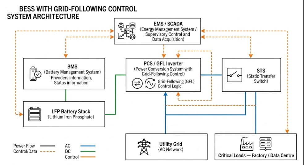
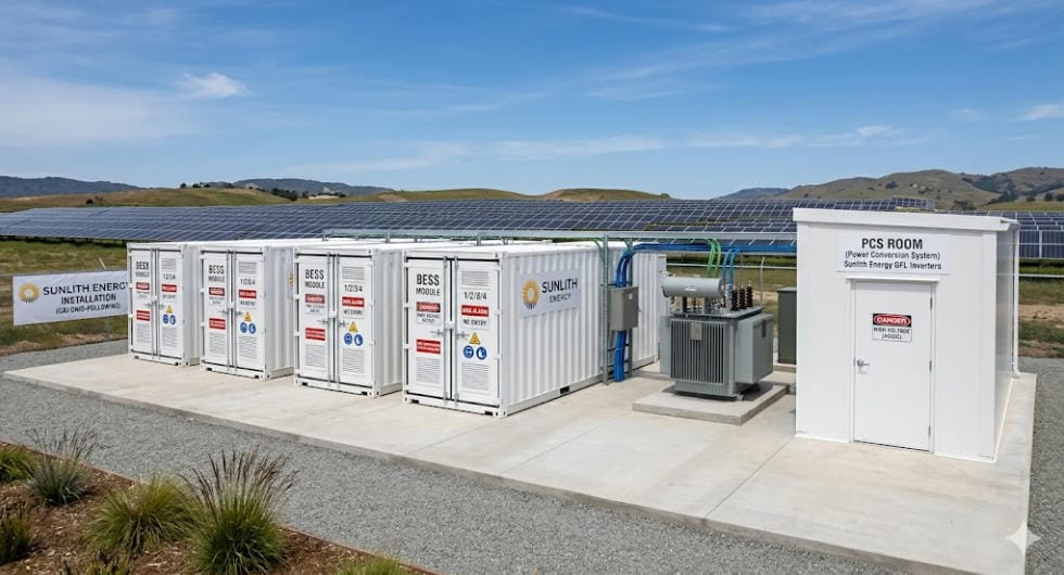
9. Key Components in a BESS Grid-Following System
A complete BESS grid-following system has several integrated layers. Each component has a specific role. Understanding all of them together is essential for good specifications and procurement decisions.
LFP Battery and BMS
LFP (Lithium Iron Phosphate) is the dominant cell chemistry for GFL BESS systems. It offers excellent thermal stability, a long cycle life of 3,500 to 6,000 cycles to 80% Depth of Discharge (DoD), and a competitive cost per kWh. The Battery Management System (BMS) monitors every cell for voltage, temperature, and state of charge.
See: Battery Management System (BMS) Explained
Power Conversion System (PCS) — the GFL Inverter
The PCS is the inverter. It performs DC-to-AC conversion and runs the GFL control algorithms — PLL, current control loops, and droop functions. For C&I applications, PCS units typically range from 50 kW to 2,500 kW per unit. For utility scale, 2.5 MW to 5 MW units are common.
See: Power Conversion System (PCS): The Heart of a BESS
Static Transfer Switch (STS) for GFL Backup Power
As described in Section 6, the STS is what enables a BESS grid-following system to deliver seamless uninterruptible power. It transfers load from the utility to the BESS in 2 to 8 milliseconds. This happens before the GFL inverter can lose its voltage reference.
Full guide: The Role of Static Transfer Switch (STS) in C&I BESS
Transformer and Grid Interface
Most C&I BESS grid-following systems connect at low voltage (400V or 480V). Larger systems use a step-up transformer to connect at medium voltage (11 kV or 33 kV). The transformer also affects the SCR at the PCC — so its impedance must be factored into the stability analysis.
10. Sizing a BESS Grid-Following System
Getting the size right from the start is critical for ROI. Oversizing wastes capital. Undersizing leaves value on the table. Here are the three key sizing considerations.
Power Rating (kW or MW)
For peak shaving, the power rating equals the target demand reduction. As an example, if a facility peaks at 2,000 kW and the target is 1,500 kW, the BESS needs at least 500 kW of discharge power. When it comes to FFR and frequency services, the power rating is determined by the contracted ancillary service volume.
Energy Capacity (kWh or MWh)
Energy capacity must sustain the required power for the needed duration. A peak shaving event might last 15 to 60 minutes. A backup power event may require 30 minutes to 4 hours. For most C&I peak shaving projects, a 2-hour duration — meaning energy equals power times two — is the standard starting point.
Sizing for Battery Degradation
LFP batteries degrade over time. As a result, a well-designed GFL system adds a 10 to 20% capacity buffer above Day 1 requirements. This ensures the system still meets performance targets at end of warranty — typically 10 years. Without this buffer, systems often fall short of contracted performance by Year 3 to 5.
See: C&I BESS Economics & ROI: Full Breakdown
11. Common BESS Grid-Following Deployment Mistakes
Based on Sunlith Energy’s project experience, certain mistakes appear most frequently. However, each one is entirely avoidable with good engineering practice.
- Local SCR Data — Skipping a short circuit ratio analysis creates massive system risks. Therefore, you must request this data from the network operator before choosing hardware.
- Faulty Factory Defaults — Inverters face severe control issues at sites with high harmonics. Because of this, engineers must tune the PLL settings during commissioning.
- Leaving Out the STS — Omitting a static switch is a critical system error. Projects that expect clean backup power from a GFL BESS without an STS will fail.
- Under-designed Protection Studies — Poorly coordinated anti-islanding settings cause frequent false alarms. To fix this, running a dedicated simulation study is a vital step.
- Battery Cell Degradation — Sizing a system purely for Day 1 needs will hurt your long-term ROI. Since batteries lose capacity over time, always design for your end-of-warranty targets.
- Without Rigorous Testing — Inverter firmware bugs are common in the field. Consequently, a full factory test is highly recommended to catch control errors early.
12. The Future of BESS Grid-Following: Hybrid Control Modes
The line between grid-following and grid-forming is already beginning to blur. The next generation of inverter platforms introduces hybrid modes that give GFL inverters some grid-forming capabilities under defined conditions.
Grid-Supportive GFL with Synthetic Inertia
New control algorithms allow BESS grid-following inverters to inject synthetic inertia — a power response proportional to the Rate of Change of Frequency (ROCOF). This helps fix the loss of mechanical inertia in high-renewable grids. It does not replicate full Grid-Forming capability. However, it meaningfully improves system inertia at a fraction of the cost.
Seamless GFL-to-GFM Mode Switching
Some advanced PCS platforms can switch automatically between GFL mode (when the grid is strong) and GFM mode (when the grid is weak or islanded) — without interrupting power delivery. Consequently, this is particularly valuable for microgrids that are normally grid-connected but need to island on demand.
BESS Grid-Following in Virtual Power Plants (VPPs)
Aggregators are grouping multiple GFL BESS assets across different C&I sites into Virtual Power Plants (VPPs). These VPPs then bid collectively into grid service markets. Each site uses a standard BESS grid-following system. Furthermore, the master platform provides the scale needed to enter the market. According to BloombergNEF, VPPs incorporating GFL BESS are forecast to exceed 50 GW of virtual capacity globally by 2030.
Source: BloombergNEF Energy Storage Market Outlook
13. Frequently Asked Questions About BESS Grid-Following
What does BESS grid-following mean?
BESS grid-following means the battery inverter synchronises its output to the existing grid voltage and frequency. Because of this, the battery follows the grid — it does not set the grid reference. This is the most common inverter control mode in battery storage today.
Can a GFL BESS provide backup power?
Yes — when paired with a Static Transfer Switch (STS). The STS transfers load from the utility to the BESS in 2 to 8 milliseconds, before the GFL inverter loses its voltage reference. As a result, critical loads experience no interruption. For more detail, see our guide on the STS.
Read more: The Role of STS in C&I BESS
What SCR is needed for BESS grid-following systems?
A minimum Short Circuit Ratio of 3 at the Point of Common Coupling is the standard engineering rule of thumb. Below SCR 2, a detailed stability analysis is mandatory. In addition, Grid-Forming inverters should be seriously considered for any site below SCR 2.
How fast does a BESS grid-following system respond to frequency events?
A modern GFL inverter with droop-based frequency response begins injecting power within 200 to 500 milliseconds of a frequency deviation. This qualifies for Fast Frequency Response (FFR) markets in most grid codes worldwide.
What battery chemistry does Sunlith Energy use for GFL BESS?
Sunlith Energy uses LFP (Lithium Iron Phosphate) chemistry as the primary choice for GFL BESS systems. NMC is also available for space-constrained applications. Contact our team to discuss your specific requirements.
What certifications apply to a BESS grid-following system?
Key certifications include UL 9540 (system level), UL 1973 (battery), UL 1741 (inverter), IEEE 1547 (interconnection), and IEC 62619 (safety). Grid code compliance requirements vary by jurisdiction. For a full breakdown, see our certifications guide.
See: UL 9540 & IEC Standards Compliance for BESS
14. Conclusion: Is BESS Grid-Following Right for Your Project?
BESS grid-following is not a compromise technology waiting to be replaced. Instead, it is the proven, cost-effective workhorse of the global energy storage industry. For the vast majority of C&I and utility-scale projects connected to strong grids, it remains the right choice — both technically and economically.
However, what separates a high-performing GFL system from an underperforming one is not the technology itself. Rather, it comes down to how the system is designed, integrated, and operated. Getting the PLL right. Sizing for end-of-warranty performance. Integrating an STS for backup power. Running a rigorous SCR analysis. Pairing the inverter with an EMS that stacks every available value stream.
At Sunlith Energy, we design complete BESS grid-following solutions engineered to perform — not just to specification on Day 1, but in the real world over the full project lifetime.
Talk to the Sunlith Energy Team →
Related Articles on Sunlith Energy
- BESS Grid-Forming Technology: The Architecture Stabilising Tomorrow’s Grid
- The Role of Static Transfer Switch (STS) in C&I BESS
- How C&I BESS Peak Shaving Lowers Demand Charges for Businesses
- How EMS Enables Advanced Grid Services Through BESS
- Power Conversion System (PCS): The Heart of a BESS
- C&I BESS Economics & ROI: Full Breakdown
- How C&I BESS Enhances Solar and Wind Power Integration
- Battery Management System (BMS) Explained
- UL 9540 & IEC Standards Compliance for BESS
- Benefits of C&I BESS for Manufacturing Facilities
- BMS vs. EMS: Understanding the Control Layers in BESS
External References
- NREL — Grid Integration of Battery Storage Research
- IEEE 1547-2018 — Standard for Interconnection of Distributed Energy Resources
- IEEE 2800-2022 — Interconnection Requirements for IBRs
- ENTSO-E — Network Code on Requirements for Grid Connection of Generators
- IEA — Batteries and Secure Energy Transitions Report
- BloombergNEF — Energy Storage Market Outlook
- U.S. DOE — Energy Storage Grand Challenge
- NERC — PRC-024 Frequency and Voltage Protective Relay Settings
- IEC 62898-3-1 — Microgrids: Technical Requirements
- EPRI — Inverter-Based Resource Grid Integration Studies