
BMS Functional Safety Explained: HARA, FMEA, and ASIL/SIL Behind BMS Certification
| ⚡ Quick Answer: What Is BMS Functional Safety? BMS functional safety is the structured process used to find and control failure risks before a battery management system reaches the field. It centers on two core methods: HARA (Hazard Analysis and Risk Assessment), which identifies hazards and ranks their risk, and FMEA (Failure Modes and Effects Analysis), which traces specific failure modes to their effects. In automotive BMS design under ISO 26262, this risk ranking is called ASIL. For stationary BESS, the equivalent rating is SIL under IEC 61508, since ASIL itself is an automotive-only term. A supplier who can show you their HARA and FMEA documentation, not just a certificate, has done the real engineering work. |
1. Why the Process Matters More Than the Certificate
Most BMS buyers ask suppliers for certifications: UL 1973, IEC 62619, sometimes UL 9540A. Those certificates matter. However, they mostly confirm the outcome, not the process behind it. BMS functional safety is that process. It is the structured method engineers use to find failure risks early. In other words, it catches problems before they become field failures or safety incidents.
For the certifications a BMS itself typically carries, see our complete battery management system guide. This article goes behind those certificates, into the HARA and FMEA process that safety engineers use to earn them in the first place.
2. HARA: How Hazards Get Identified and Ranked
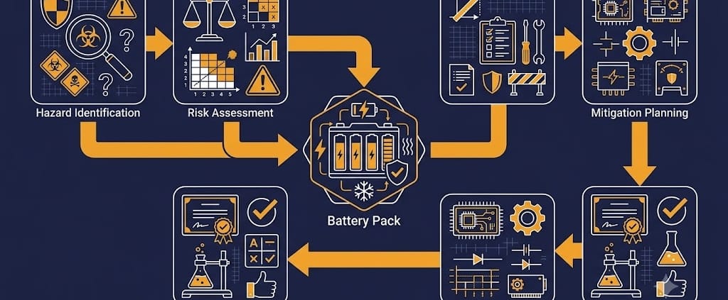
HARA stands for Hazard Analysis and Risk Assessment. It is the starting point of any BMS functional safety process. First, engineers define the “item” under review — for example, the high-voltage battery pack and its BMS. Then they ask a simple question: what could go wrong, and how bad would it be?
A typical HARA example for a BMS looks at overvoltage detection during charging. If that detection fails, the battery can overcharge. In the worst case, this leads to thermal runaway. As a result, HARA ranks this kind of hazard using three factors: how severe the harm could be, how often the situation is likely to occur, and how controllable it is once it starts. Together, these three factors produce a risk classification for that specific hazard.
3. From HARA to ASIL or SIL: Why the Terms Differ Between EV and BESS
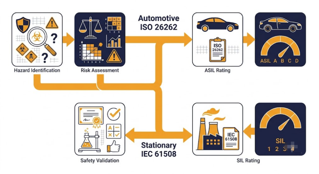
Here is where a lot of BMS content gets confusing. In automotive functional safety, ISO 26262 assigns each hazard an ASIL rating. ASIL stands for Automotive Safety Integrity Level, and it ranges from ASIL A at the low end to ASIL D at the high end. Notably, ASIL is an automotive-only term. It only applies under ISO 26262.
Stationary BESS does not use ISO 26262 or ASIL at all. Instead, industrial and stationary battery systems typically reference IEC 61508, the foundational functional safety standard for industrial equipment. Under this standard, the equivalent risk rating is called SIL, or Safety Integrity Level. It ranges from SIL 1 at the low end to SIL 4 at the high end. IEC 62619, the safety standard most directly relevant to stationary lithium battery systems, builds on this same risk-based approach.
In short: if a supplier quotes an ASIL rating for a stationary BESS product, ask why. That term belongs to automotive design. For BESS, the correct reference point is SIL under IEC 61508, or the specific requirements in IEC 62619.
4. FMEA: Finding Failure Modes Before They Find You
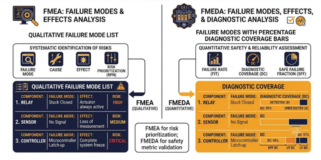
Once HARA has ranked the hazards, FMEA takes over next. FMEA stands for Failure Modes and Effects Analysis. It works from the bottom up. First, engineers list every plausible way a component can fail. Then, they trace each failure forward to its effect on the system.
For a BMS, a typical FMEA entry might look like this: a voltage sensing connector goes loose. That failure causes a false voltage reading. In turn, the false reading could let the BMS miss a real overvoltage condition. For each entry, engineers also note a detection or mitigation mechanism. For example, this might be a redundant voltage check, or a plausibility test that catches an implausible reading before it reaches a safety-critical decision.
A properly documented FMEA does not just list failures. It also proves how each one gets prevented or caught. That proof is what an auditor or a certification body actually reviews.
5. FMEDA: When Hardware Diagnostics Get Quantified
FMEDA extends FMEA with numbers. It stands for Failure Modes, Effects, and Diagnostics Analysis. Rather than only describing failure modes in words, FMEDA calculates a diagnostic coverage percentage for each one. In other words, it shows what fraction of that failure mode’s occurrences the system’s safety mechanisms will actually catch.
This matters for BMS functional safety because a hardware design is only as safe as its worst-covered failure mode. A BMS might claim excellent overall diagnostic coverage. Even so, it could still leave one connector or one sensor path poorly monitored. FMEDA is what surfaces that gap before a customer, not an incident, does.
6. What a Real BMS Functional Safety Process Actually Produces
A supplier who has genuinely run this process should, therefore, be able to produce specific documents, not just a summary slide. Look for these deliverables:
- A HARA report, listing each identified hazard with its severity, exposure, and controllability ratings, plus the resulting SIL (for BESS) or ASIL (for automotive) classification.
- Safety goals derived from the HARA. These are stated as top-level requirements, for instance: “prevent cell overvoltage during charging under single-point failure conditions.”
- A functional safety concept. This translates each safety goal into requirements — first functional, then technical, down to the hardware and software level.
- An FMEA or FMEDA report, listing failure modes, their effects, and the safety mechanism that detects or prevents each one.
- A safety case or validation report. This shows how testing confirmed the safety mechanisms actually work as designed.
These safety mechanisms must map seamlessly across the entire battery topology. For a closer look at how these safety-critical diagnostic lines and communication protocols are distributed across physical hardware layers, see our guide to centralised, modular, and wireless BMS architecture.
For the specific BMS algorithms — SOH, SoP, isolation monitoring, safety diagnostics — that these safety mechanisms often rely on, see our BMS algorithms guide. In short, functional safety analysis is the process that justifies why those algorithms exist and how thoroughly they were tested.
7. Questions to Ask Your Supplier About BMS Functional Safety
Before finalizing your procurement, it helps to have a structured framework for vetting a vendor’s safety claims. For a comprehensive breakdown of what to look for beyond documentation, review our BMS supplier evaluation checklist.
- Can you show me the HARA report for this BMS, including the hazards identified and their risk ratings?
- Is your safety rating expressed as SIL under IEC 61508, or ASIL under ISO 26262? Does that match whether this is a stationary or automotive product?
- Can you provide the FMEA or FMEDA report showing diagnostic coverage for each major failure mode, not just one overall percentage?
- What safety goals came out of your HARA? How do they map to the BMS features you actually ship?
- Has an independent third party reviewed this functional safety process, or is it entirely self-assessed?
Conclusion: Ask for the Process, Not Just the Certificate
A certification number tells you a BMS passed a test. BMS functional safety documentation tells you why it should pass. It also shows what specific hazards the engineering team found and controlled along the way. For BESS projects, insist on SIL ratings under IEC 61508 or IEC 62619 evidence. Do not accept an automotive ASIL number instead, since it simply does not apply. Ask to see the HARA and FMEA reports directly. After all, a supplier with nothing to show beyond a certificate has likely skipped the part of the work that actually keeps a battery pack safe.
| ☀️ Need a BMS Functional Safety Review for Your BESS Project? Sunlith Energy reviews BMS functional safety documentation — HARA reports, FMEA coverage, and SIL classification — for BESS projects from 50 kWh upward. Contact us before you finalize a supplier. |
Frequently Asked Questions About BMS Functional Safety
What is the difference between HARA and FMEA in BMS functional safety?
HARA identifies hazards at the system level and ranks their risk using severity, exposure, and controllability. FMEA, on the other hand, works at the component level. It traces specific failure modes up to their effects on the system. Typically, HARA comes first and sets the risk target. FMEA then verifies the design meets that target.
Why doesn’t ASIL apply to stationary BESS?
ASIL, or Automotive Safety Integrity Level, is defined specifically within ISO 26262, an automotive functional safety standard. Stationary BESS does not fall under that standard. Instead, it typically references IEC 61508, whose equivalent risk rating is called SIL, or Safety Integrity Level.
What is FMEDA and how is it different from FMEA?
FMEDA, or Failure Modes, Effects, and Diagnostics Analysis, extends FMEA by adding a quantified diagnostic coverage percentage for each failure mode. Standard FMEA describes failure modes and their effects in words. FMEDA, by contrast, calculates how much of each failure mode the system’s diagnostics will actually catch.
What documents should a BMS supplier provide as proof of functional safety work?
At minimum, ask for the HARA report and the safety goals derived from it. Also request the FMEA or FMEDA report, plus a safety validation document showing that testing confirmed the safety mechanisms work as intended. If a supplier can only provide a certificate, with none of these underlying documents, they have likely not completed a full functional safety process.
Does IEC 62619 replace the need for a HARA and FMEA process?
No. IEC 62619 sets safety requirements specifically for stationary lithium battery cells and systems. However, it does not replace the underlying HARA and FMEA process used to design and verify BMS safety mechanisms. Instead, the two work together: IEC 62619 sets the target, and the functional safety process is how a supplier gets there and proves it.
BMS Architecture Explained: Centralised vs Modular (Master-Slave) vs Wireless BMS for BESS
| ⚡ Quick Answer: Which BMS Architecture Is Right for a BESS? BMS architecture comes in three main types: centralised (one controller handles all cells directly), modular master-slave (each module has its own slave BMS reporting to a master), and wireless BMS (modules communicate without a physical data harness). Centralised suits small residential systems. Modular master-slave is the standard for commercial and utility-scale BESS. Wireless BMS is maturing fast in EVs but remains early-stage for grid-scale BESS, mainly due to EMI risk in high-power environments and a 25-40% cost premium. |
1. Why BMS Architecture Matters Beyond Just System Size
Most guides treat BMS architecture as a simple size question: small systems get one BMS, big systems get many. That is true as a starting point. But the choice also decides how a fault in one module affects the rest of the pack, how much wiring a technician has to run and maintain, and how easily the system scales later without a redesign.
For the basics of what a BMS does — monitoring, protection, balancing, and communication — see our complete battery management system guide. This article goes one level deeper: the wiring topology inside modular designs, and the wireless BMS option now entering the market.
2. Centralised BMS: How a Single Controller Works
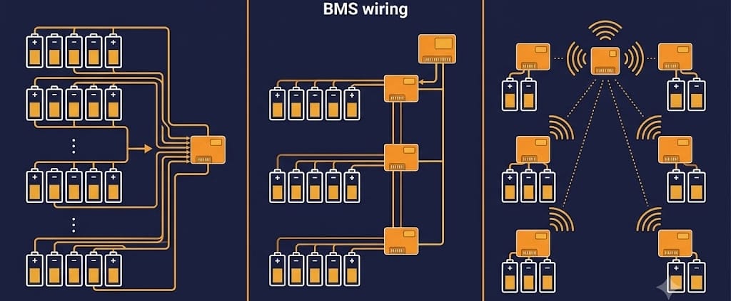
In a centralised design, one controller connects directly to every cell in the pack. It handles voltage monitoring, balancing, and protection for all cells from a single board. There is no master-slave hierarchy here, simply because there is only one controller.
This setup keeps cost and complexity low. As a result, it works well for residential systems under roughly 100 kWh. Cell counts here typically stay in the range of a few dozen to a few hundred. Beyond that range, though, the wiring harness needed to connect every single cell to one board becomes heavy, expensive, and hard to service.
A centralised design also has a single point of failure built in. If the central controller fails, the entire pack loses monitoring and protection at once. For small systems, this risk is usually acceptable, given the lower stakes and lower cost. For larger systems, however, it is not.
3. Modular (Master-Slave) BMS Architecture: How It Works
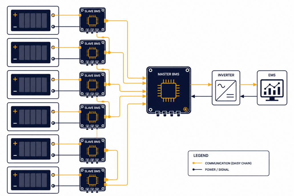
A modular design, often called master-slave, splits the job across many controllers instead of one. Each battery module gets its own slave BMS board. That slave handles local cell monitoring and balancing for its own module only. In turn, all slave boards report up to a central master BMS, which coordinates the full pack and talks to the inverter and EMS.
This setup scales far better than a centralised design. For instance, adding another module usually means adding another slave board to the daisy chain, not redesigning the whole harness. As a result, it is the standard choice for commercial and utility-scale BESS today.
The real engineering decision here, though, is not whether to use master-slave. Most large systems already do. Instead, it comes down to which wiring protocol connects the slaves to the master. It also depends on how much independence each slave keeps if it loses contact with the master.
4. Wiring Protocols in Modular Designs: isoSPI vs CAN vs LIN
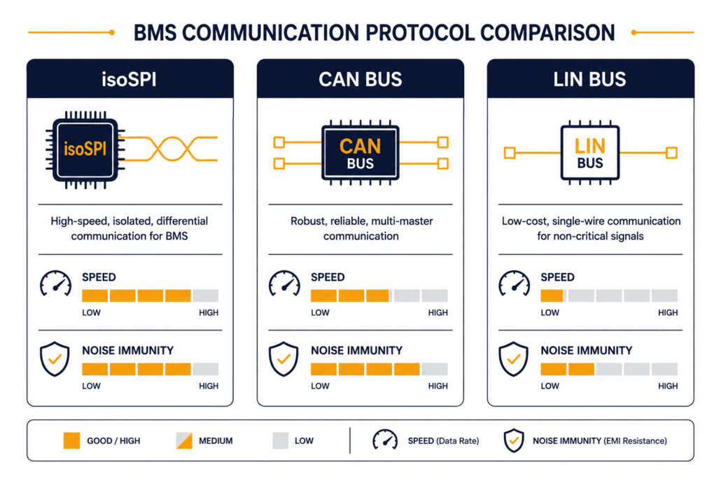
Three communication protocols dominate the physical link between slave boards and the master. Each one makes a different tradeoff between speed, noise immunity, and cost. For a deeper look at how these networks manage data across the entire system, read our guide on BESS communication protocols.
- isoSPI — an isolated version of SPI (Serial Peripheral Interface), built specifically for daisy-chaining BMS slave boards. It runs over a simple twisted pair. It tolerates the electrical noise inside a battery pack well, and it supports fast data rates. As a result, many premium BMS platforms use isoSPI for the slave-to-slave and slave-to-master link inside one rack.
- CAN bus — the same protocol widely used in automotive and industrial systems. CAN is robust, well standardized, and easy to integrate with third-party inverters and EMS platforms. Because of this, it is common for the master-to-inverter and master-to-EMS link, and sometimes for slave-to-master links in simpler designs.
- LIN bus — a lower-cost, lower-speed protocol used for less time-critical links, such as temperature sensor networks within a module. In short, it trades speed for lower wiring and component cost.
In practice, many BESS platforms combine protocols. isoSPI handles fast, noise-resistant slave communication within a rack. CAN bus then takes over at the master level for system-wide integration. Ask your supplier which protocol handles which link. Otherwise, a design built entirely on one lower-speed protocol may struggle to keep up with fast balancing or protection response at scale.
5. Wireless BMS Architecture: How It Works and Where It Stands Today
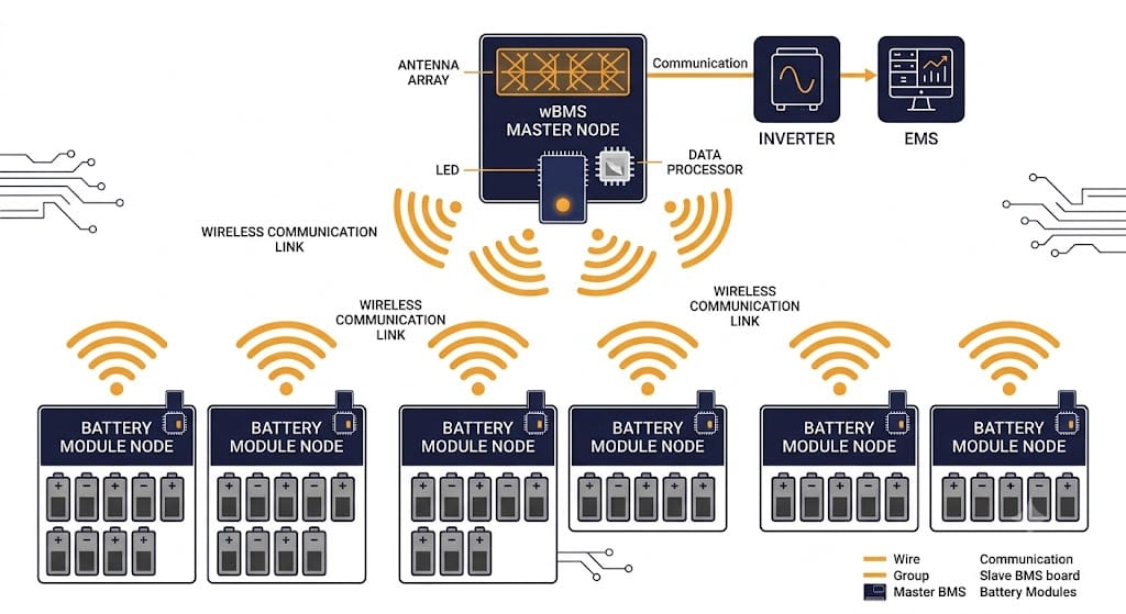
Wireless BMS removes the physical data harness between modules entirely. Instead of isoSPI or CAN wiring, slave boards communicate with the master using Bluetooth Low Energy, Zigbee, or a proprietary 2.4GHz radio protocol. Cell voltage, temperature, and balancing commands all travel wirelessly instead of over copper.
Why Wireless BMS Is Appealing
The appeal is real. Going wireless removes the weight, cost, and failure points of a physical wiring harness. It also simplifies manufacturing, since there are fewer connectors to install and fewer wiring faults to test for. This matters most where running a wired harness is expensive or awkward. Second-life BESS built from repurposed EV modules, for example, often have mismatched connector layouts that make wiring harder than usual.
Why Utility-Scale BESS Isn’t There Yet
That said, wireless BMS is not yet the default choice for grid-scale BESS, and current research explains why. A peer-reviewed review of wireless BMS technology, published in MDPI Energies, notes that wireless systems remain at an early stage of maturity. This is especially true for high-power settings, where electromagnetic interference from PCS switching can disrupt the link.
Three practical concerns keep wireless BMS out of most utility-scale BESS today. First, EMI susceptibility: high-power switching from inverters and PCS equipment can interfere with the wireless signal. That kind of interference in a safety-critical monitoring link is a serious risk, not a minor inconvenience. Second, cost: wireless hardware currently runs 25-40% more than equivalent wired systems, which matters a great deal at grid scale. Third, standardization: there is no universal wireless protocol yet. As a result, mixing components from different makers is harder than it is with wired isoSPI or CAN systems.
For now, wireless BMS is furthest along in electric vehicles, where weight savings translate directly into range. It is also gaining ground in residential solar-plus-storage products, where simple assembly and remote installation flexibility matter more than they do at utility scale. For grid-scale BESS specifically, expect wired modular designs to stay the standard for the next several years. Wireless will likely enter first through pilot projects and second-life storage deployments.
6. Comparing Centralised, Modular, and Wireless BMS Architecture Options
| Factor | Centralised | Modular (Master-Slave) | Wireless |
|---|---|---|---|
| Typical system size | Under 100 kWh | 100 kWh to multi-MWh | EVs, residential ESS today; utility-scale still early |
| Wiring complexity | High at scale — every cell wired to one board | Moderate — daisy-chained per module | Minimal — no data harness |
| Failure isolation | Poor — single point of failure | Good — slave boards can protect locally | Depends on link redundancy design |
| Cost | Low | Moderate, scales predictably | 25-40% premium over wired today |
| Maturity for BESS | Proven, residential standard | Proven, commercial/utility standard | Early-stage for grid-scale |
7. Failure Isolation: The Real Safety Question Behind the Design
The most important question about any BMS design is not which protocol it uses. Instead, it is what happens when one part of the system fails. In a well-designed modular setup, each slave board keeps protecting its own module even if it loses contact with the master. This relies heavily on the local execution of core BMS algorithms
to calculate state-of-charge (SOC) and state-of-health (SOH) independently. In a poorly designed system, however, the whole pack’s protection depends entirely on the master controller.
Evaluating these single points of failure is a core part of rigorous risk assessment. For a deeper look at how engineers map out these risks and establish safety goals, see our guide on BMS functional safety, HARA, and FMEA.
So ask your supplier directly: if the master BMS fails or loses communication, does each module still enforce its own voltage and temperature limits? If the answer is no, that design has a hidden single point of failure, no matter how many slave boards it has.
8. Choosing the Right BMS Architecture for Your BESS Project
For residential and small commercial systems under 100 kWh, a centralised design is usually the right call, since it is simpler, cheaper, and proven. For commercial and utility-scale BESS, on the other hand, modular master-slave is the standard. Here, the real decision is choosing a supplier whose wiring protocol and failure-isolation design hold up under real-world conditions. Wireless BMS, meanwhile, is worth watching, and worth specifying for second-life or hard-to-wire retrofit projects today. Still, it is not yet the safe default for new utility-scale BESS.
9. Questions to Ask Your Supplier About BMS Architecture
- Is the design centralised or modular master-slave, and does that match our system size?
- What wiring protocol connects slave boards to the master — isoSPI, CAN, or a mix?
- If the master fails or loses communication, does each slave module still enforce its own protection limits independently?
- If any wireless components are proposed, what EMI testing has been done in a real high-power switching environment, not just a lab bench test?
- How does the system scale if we add modules later — does it require a wiring redesign, or just an extension of the existing daisy chain?
Conclusion: BMS Architecture Shapes Reliability as Much as Chemistry Does
Cell chemistry gets most of the attention in a BESS purchase decision. However, the design behind the cells deserves the same scrutiny. A centralised setup suits small systems. Modular master-slave is the proven standard for commercial and utility-scale BESS. Wireless BMS is real, growing, and worth watching, but for grid-scale projects today, it remains an early-stage option, not a default choice.
Whatever design a supplier proposes, ask the failure-isolation question directly. After all, a pack with excellent cells and a poorly isolated BMS is still a fragile system.
| ☀️ Need a BMS Architecture Review for Your BESS Project? Sunlith Energy reviews BMS architecture proposals — wiring topology, failure isolation, and protocol choice — for BESS projects from 50 kWh upward. Contact us before you finalize a supplier. |
Frequently Asked Questions About BMS Architecture
What is the difference between centralised and modular BMS architecture?
A centralised design uses one controller connected directly to every cell in the pack. A modular design, also called master-slave, works differently. It splits monitoring across multiple slave boards — one per module — that report to a central master controller. As a result, modular designs scale better for larger systems.
Is wireless BMS ready for utility-scale BESS?
Not yet, as a default choice. Wireless BMS works well in electric vehicles and is gaining ground in residential storage. However, electromagnetic interference from high-power switching, a 25-40% cost premium, and a lack of standard protocols keep it early-stage for grid-scale BESS today.
What is isoSPI and why does it matter for battery pack wiring?
isoSPI is an isolated communication protocol built for daisy-chaining BMS slave boards. It runs over a simple twisted pair, resists the electrical noise inside a battery pack, and supports fast data rates. For this reason, it is common in modular designs for grid-scale BESS.
Why does failure isolation matter more than the design type?
A modular design only delivers its safety benefit under one condition: slave boards must keep protecting their own modules when they lose contact with the master. Otherwise, that modular design still depends entirely on the master controller. In that case, it has the same single point of failure as a centralised system, just with extra hardware.
Can I mix wired and wireless BMS in one BESS?
In principle, yes, and this is already happening in some second-life storage projects that use repurposed EV modules with mismatched wiring. In practice, though, mixing protocols adds integration complexity. So confirm with your supplier how a hybrid design handles failure isolation and data sync between the wired and wireless segments.
BMS Cycle Counting Explained: EFC vs. Rainflow Algorithms
| ⚡ Quick Answer: What Is BMS Cycle Counting? BMS cycle counting turns raw current and SOC data into a wear metric. First, most systems track Ah/kWh throughput and convert it into Equivalent Full Cycles (EFC). Next, advanced platforms run a rainflow algorithm that splits a messy SOC trace into discrete, depth-weighted cycles. Finally, premium BMS platforms add a stress-weighted layer for C-rate and temperature. As a result, BMS cycle counting feeds SOH and RUL models, not just a simple warranty odometer. |
BMS cycle counting sounds simple. In reality, it is one of the least understood functions inside a Battery Management System. Every BESS datasheet shows a number like “6,000 cycles to 80% SOH.” Few buyers ask the obvious follow-up question: how does the BMS actually reach that count in the field? A grid-connected battery rarely swings cleanly from 100% to 0% and back. Instead, it moves up 12%, down 4%, up 20%, down 7%, dozens of times a day. Dispatch signals, solar variability, and frequency-regulation events all drive this pattern. Because of this, converting a noisy trace into one clean cycle number is a genuinely hard firmware problem.
This guide explains exactly how BMS cycle counting works today. First, we cover why simple threshold counting fails for BESS. Next, we break down the rainflow algorithm, borrowed from mechanical fatigue analysis. Then, we show how it solves the partial-cycle problem. Finally, we explain why the datasheet number rarely matches what your BMS reports in the field. For the state-estimation layer this article builds on, see our guides to BMS SOC estimation methods and BMS algorithms explained.
1. Why BMS Cycle Counting Is Harder Than It Sounds
A cycle sounds easy to count: full charge, full discharge, done. However, “one cycle” has no single agreed definition outside the lab. A cell tested for its datasheet rating runs controlled, repeatable 100%–0% swings at a fixed C-rate and temperature. However, a cell inside a grid-connected BESS does nothing of the sort.
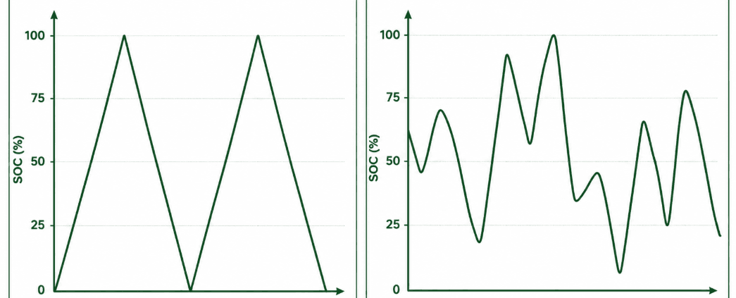
In practice, real-world SOC traces look like a jagged mountain range. Hundreds of small reversals happen every day. A dispatch instruction, a passing cloud, or a short frequency-regulation event can each trigger one. If BMS cycle counting logged every reversal as a cycle, one day of frequency regulation could register thousands of cycles. That would badly overstate wear. On the other hand, a threshold-only method misses just as much. A peak-shaving BESS that stays within the 20–80% band could show almost zero full cycles. Yet it may still have years of hard use behind it.
Neither outcome helps warranty tracking or SOH modelling. For this reason, BMS and EMS firmware rely on purpose-built cycle-counting algorithms instead of simple threshold logic. According to Energy-Storage.News, the industry still lacks one universal definition of a cycle. That gap is exactly why several competing counting methods exist side by side today.
2. Method 1: Simple Threshold-Based BMS Cycle Counting
The most basic form of BMS cycle counting sets two SOC thresholds, typically near 95% and 5%. Firmware then adds one to a counter each time the pack completes a full traverse between them. This approach is cheap to build and easy to explain. As a result, it shows up often in low-cost consumer BMS platforms.
For stationary BESS, though, this method falls short. Most BESS installations rarely complete a true top-to-bottom swing. Dispatch strategies deliberately avoid the SOC extremes to protect cycle life (see our guide on the 20/80 rule for batteries). Consequently, a system cycling between 20% and 80% SOC may never trigger a single “full cycle” under this method. That can happen even after years of heavy use. This undercount is precisely why the industry moved toward throughput-based BMS cycle counting instead.
3. Method 2: BMS Cycle Counting With Ah-Throughput (EFC)
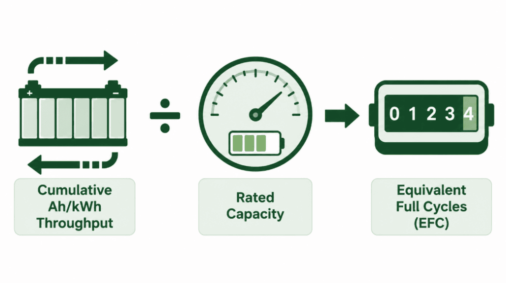
This method sits behind almost every commercial BESS warranty. Rather than watching for full swings, the BMS integrates current over time. It uses the same Coulomb-counting math built for SOC estimation. In other words, it adds up every amp-hour that flows in or out of the pack, in either direction. The BMS then divides that cumulative throughput by the pack’s rated capacity. The result is Equivalent Full Cycles, or EFC.
For example, a 500 kWh BESS that has processed 1,000 kWh of cumulative throughput has logged 2 EFC. This version of BMS cycle counting is simple. In addition, it is cheap to run continuously. And it works no matter how the pack is actually cycled, since it never requires a full 100–0% swing.
The Core Blind Spot of EFC Tracking
EFC has one well-known limitation: it treats every amp-hour the same, no matter how deep the swing was. As Energy-Storage.News notes, EFC alone cannot tell one cycle at 100% depth of discharge apart from two cycles at 50% DoD, or ten cycles at 10% DoD. Yet these three patterns stress the cell chemistry quite differently. So, shallow frequent cycling and deep infrequent cycling can log an identical EFC number. Even so, they age the pack at very different rates.
Many BMS platforms partly correct for this. They re-base the EFC denominator against current estimated capacity instead of nameplate capacity. That keeps the figure accurate as the pack fades. Even so, the core blind spot remains. This gap is exactly what rainflow-based BMS cycle counting was built to close.
4. Method 3: Rainflow-Based BMS Cycle Counting for Partial Cycles
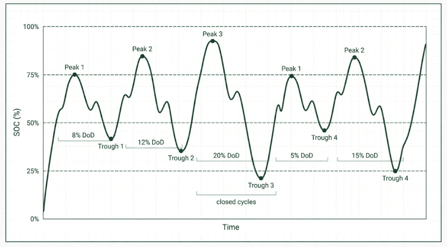
Rainflow counting began as a tool for mechanical fatigue analysis. Engineers used it to turn a noisy load history into a clean set of discrete stress cycles. Battery researchers later adapted the same logic for SOC traces. A peer-reviewed ScienceDirect study on grid-integrated BESS cycle counting confirms it as the most widely used cycle-counting algorithm in the field today. Rainflow-based BMS cycle counting solves what EFC cannot: it identifies the depth of every individual swing, not just the running total.
How the Rainflow Algorithm Works Step-by-Step
- The BMS records every local extremum in the SOC trace. In other words, it logs every point where the pack switches from charging to discharging, or back again.
- It then calculates the SOC delta between each set of three consecutive extrema.
- Consequently, If the middle delta is smaller than or equal to both neighbours, that segment counts as one closed, complete cycle at that specific depth.
- The BMS removes those two points. Then it repeats the comparison on the remaining trace — much like water draining off a stepped rooftop, which is where the algorithm gets its name.
- The output is a list of discrete cycles, each tagged with its own depth of discharge. For example: “47 cycles at ~80% DoD, 1,200 cycles at ~15% DoD,” instead of one flattened EFC figure.
One detail matters here: rainflow-based BMS cycle counting applies to depth of discharge, not absolute SOC. A swing from 80% down to 70% and a swing from 20% down to 10% both register as the same 10%-DoD event. Both count as equivalent stress. This lines up with how degradation models actually work, since most treat wear as a function of cycle depth, not the absolute SOC band it happens in.
Because rainflow output preserves depth data, it feeds straight into the DoD-weighted models used by SOH and RUL algorithms. That is the same layer we cover in our guide to BMS algorithms explained.
5. Method 4: Stress-Weighted BMS Cycle Counting
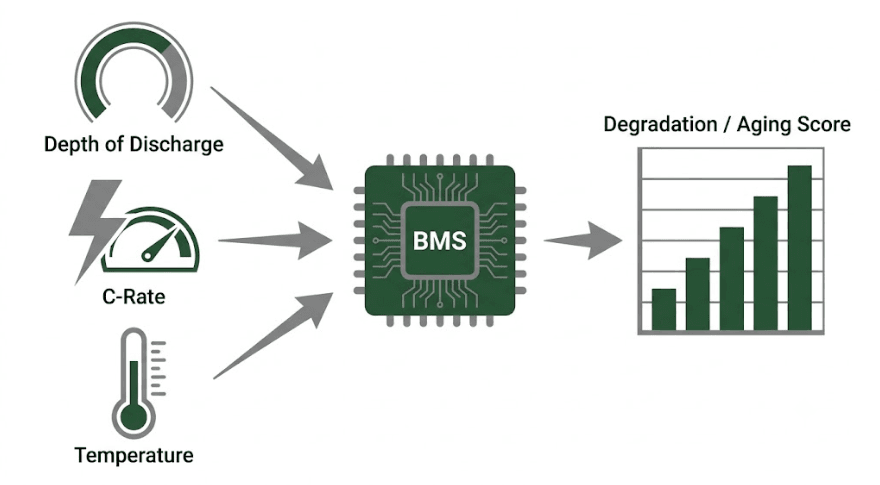
The most advanced BMS and EMS platforms push rainflow-based BMS cycle counting one step further. Instead of tallying cycles by depth alone, each identified cycle passes through a stress function. That function also factors in the C-rate and cell temperature present during that specific cycle. For instance, a 60%-DoD cycle at 0.2C and 25°C is far gentler than the same 60%-DoD cycle at 1.5C and 40°C. A stress-weighted counter reflects that difference clearly.
Rather than reporting a raw cycle count, this method builds a running “degradation” or “aging” score. That score, not the raw EFC number, feeds the most accurate RUL models. This is also why two BESS units with an identical EFC count can end up with very different projected remaining life.
6. How Firmware Filters Noise Before BMS Cycle Counting Begins
Raw current-sensor data is noisy. Grid-frequency jitter, brief EMS corrections, and normal sensor tolerance all create tiny, meaningless direction reversals in the SOC trace. Sometimes there are hundreds per hour. Feed that data straight into a rainflow algorithm, and the result is an explosion of trivial micro-cycles. Those micro-cycles overstate wear.
To prevent this, production BMS cycle counting firmware applies a minimum-delta, or hysteresis, threshold. A direction reversal only counts as a genuine local extremum once SOC has moved by some minimum amount, commonly 1–2%. Only then does it enter the counting algorithm. Firmware treats smaller reversals as noise and ignores them.
This single design choice separates a BMS that produces warranty-defensible cycle data from one that does not. Set the threshold too low, and cycle counts inflate from sensor noise. Set it too high, and the BMS misses genuine shallow cycling that still adds to ageing. Therefore, always ask your BMS supplier what hysteresis threshold their firmware applies. Datasheets rarely publish this figure. Yet it directly shapes every downstream SOH and warranty number.
7. Comparing the Four Cycle-Tracking Methods
| Method | What It Captures | DoD-Aware? | Best For | Main Limitation |
|---|---|---|---|---|
| Threshold counting | Full 95%–5% traverses only | No | Simple consumer packs | Badly undercounts partial-cycling BESS |
| Ah-throughput (EFC) | Cumulative current throughput | No | Warranty reporting, simple dispatch | Cannot distinguish deep vs. shallow cycling |
| Rainflow counting | Each discrete swing, by depth | Yes | SOH modelling, mixed dispatch profiles | More compute-intensive; needs clean extrema |
| Stress-weighted counting | Depth + C-rate + temperature | Yes | RUL prediction, warranty defensibility | Requires a validated stress model per cell type |
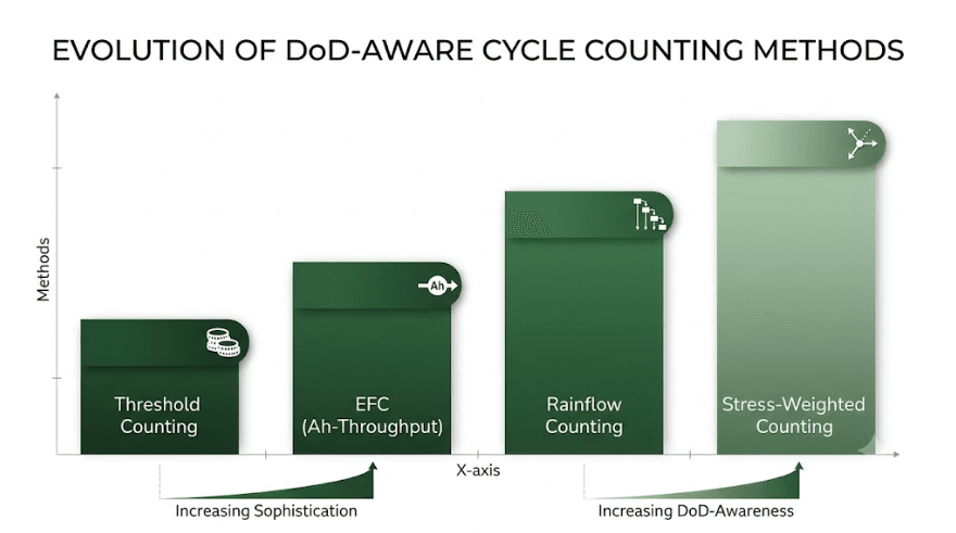
Most premium BMS platforms do not rely on just one method. Instead, they report EFC for simple dashboards and warranty tracking. Meanwhile, they run rainflow and stress-weighted BMS cycle counting in the background to feed SOH and RUL models. If a supplier says their BMS “counts cycles” without naming a method, ask directly. The gap between threshold counting and stress-weighted rainflow counting can differ by an order of magnitude in reported wear.
8. Why Datasheet Numbers Rarely Match Real-World Wear
A supplier’s “6,000 cycles to 80% SOH” claim is almost always a lab-derived EFC figure. Labs measure it under fixed, controlled conditions. That means a specific depth of discharge, often 80–90%, a specific C-rate, often 0.5C–1C, and a specific ambient temperature, often 25°C. Change any one of these variables in the field, and the real cycle-life outcome shifts. Sometimes it shifts substantially. We cover this relationship in detail in our guide to how temperature affects LFP battery cycle life. You can also model your own scenario with our battery cycle life calculator. For a broader reference on stationary lithium battery testing conditions, see IEC’s battery safety and performance standards.
In practice, your BMS’s in-field EFC or rainflow-weighted count measures a different operating profile than the datasheet number. A BESS running frequent shallow cycles at moderate temperature may outlive its rated cycle count in calendar terms. Meanwhile, one running deep cycles at high ambient temperature may fall short of it. Neither outcome means the datasheet number was wrong. It simply means BMS cycle counting and lab-rated cycle life measure two related, but distinct, things.
9. Questions to Ask About Your Supplier’s BMS Cycle Counting Method
- Which cycle-counting method does the firmware run: threshold, raw EFC, rainflow, or stress-weighted? A BMS that only reports raw EFC cannot show how deep-cycling patterns affect real degradation.
- What minimum-delta, or hysteresis, threshold filters noise before a reversal counts as a cycle? An unpublished or unreasonably low threshold can quietly inflate cycle counts.
- Is the EFC denominator based on nameplate capacity or current estimated capacity? Using nameplate capacity for the pack’s whole life understates EFC as the cell ages.
- Does the cycle-counting output feed the SOH and RUL algorithms directly, or are they calculated separately? Disconnected pipelines often cause inconsistent SOH and warranty reporting.
- What DoD, C-rate, and temperature conditions does the warranty’s rated cycle-life figure assume? This baseline is what your field cycle count should be compared against, not treated as a universal number.
For the broader procurement framework this fits into, see our guide to evaluating a BESS supplier’s BMS.
10. Worked Example: EFC vs. Rainflow Counting
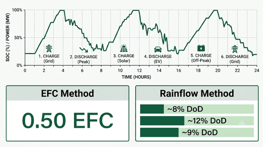
Consider a 100 kWh BESS module running a frequency-regulation profile for one day. It discharges 8 kWh, charges 5 kWh, discharges 12 kWh, charges 10 kWh, discharges 6 kWh, and charges 9 kWh. That adds up to 50 kWh of cumulative throughput.
| Method | Calculation | Result |
|---|---|---|
| Ah-throughput (EFC) | 50 kWh cumulative throughput ÷ 100 kWh rated capacity | 0.50 EFC for the day |
| Rainflow (illustrative) | Decomposed into 3 discrete cycles at ~8%, ~12%, ~9% DoD | 3 shallow cycles logged, none flattened into one number |
While both numbers are technically correct, they answer different questions. The 0.50 EFC figure shows up on a simple throughput dashboard and feeds warranty-cycle tracking. The rainflow breakdown, however, is what a SOH model actually needs. Three shallow 8–12% DoD cycles age a cell differently than one 50%-DoD cycle would. That holds true even though both scenarios can produce the same EFC total.
Conclusion: BMS Cycle Counting Is a Modelling Choice, Not a Simple Tally
A BMS does not count cycles the way a person counts laps around a track. Instead, it reconstructs a cycle metric from a continuous current and SOC trace. Each method trades simplicity for accuracy differently. Threshold counting is too crude for real BESS dispatch. EFC is the industry-standard warranty metric, yet it stays blind to depth of discharge. Rainflow-based BMS cycle counting recovers that missing depth information. It breaks messy, real-world SOC traces into discrete, weighted cycles. Stress-weighted counting goes further still. It folds in C-rate and temperature to build the aging score that actually drives accurate RUL prediction.
For BESS buyers and operators, the lesson is simple. Do not take “the BMS tracks cycle count” at face value. Instead, ask which method it uses. Ask how it filters sensor noise. And ask how that number connects to the SOH and RUL figures you will eventually rely on for warranty claims and second-life valuation.
| ☀️ Need a BMS Cycle Counting and SOH Methodology Review? SunLith Energy reviews BMS cycle counting implementation, EFC and rainflow methodology, and SOH-RUL linkage for BESS projects from 50 kWh upward. Contact us before you commit to a supplier. |
Frequently Asked Questions
How does BMS cycle counting work?
BMS cycle counting converts raw current and SOC data into a wear metric. Most systems first calculate cumulative Ah or kWh throughput. They then convert it into Equivalent Full Cycles. More advanced platforms add a rainflow algorithm on top. It breaks the SOC trace into discrete cycles at their true depth of discharge, filtering out small reversals below a set noise threshold.
What is an Equivalent Full Cycle (EFC) in BMS cycle counting?
An EFC is the standard unit behind most BMS cycle counting for warranty purposes. The BMS sums all Ah or kWh throughput — every unit of charge or discharge, in either direction. It then divides that total by the pack’s rated or current estimated capacity. Two cycles at 50% depth of discharge, and one cycle at 100% depth of discharge, both produce 1 EFC.
Why does depth of discharge matter if EFC already tracks total throughput?
Because EFC only tracks the total charge moved, not how it was distributed. A cell that goes through one deep 100%-DoD cycle experiences different stress than one that goes through ten shallow 10%-DoD cycles. Yet both can produce the same EFC total. Rainflow-based BMS cycle counting exists specifically to preserve this depth information for accurate SOH and RUL modelling.
What is rainflow counting, and why does BMS cycle counting use it?
Rainflow counting is an algorithm first built for mechanical fatigue analysis. Applied to a battery’s SOC trace, it identifies local turning points. It then pairs them into discrete, complete cycles at their true depth of discharge, instead of one flattened throughput number. This makes it the preferred method for BMS cycle counting on BESS platforms with irregular, partial-cycling dispatch profiles.
Why doesn’t my BESS ever seem to reach the cycle count on its datasheet?
The datasheet figure is almost always measured under fixed lab conditions: a specific depth of discharge, C-rate, and temperature. If your system cycles more shallowly, at a gentler C-rate, or at cooler temperatures, its real-world BMS cycle counting output accumulates more slowly than the lab figure implies. The reverse is true under harsher conditions.
Can two BESS units show the same cycle count but have different remaining life?
Yes. Raw EFC, and even simple cycle counts, do not capture the temperature and C-rate conditions each cycle occurred under. This is why advanced BMS cycle counting adds a stress-weighted layer. It produces a degradation score rather than a plain cycle number, which feeds more accurate Remaining Useful Life predictions than cycle count alone.

BMS Algorithms Explained: SOH Estimation, SoP, SoE, Cell Balancing, and Safety Diagnostics for BESS
| ⚡ Quick Answer: What Are BMS Algorithms? BMS algorithms go far beyond SOC estimation. A production BMS runs several algorithms at once: SOH estimation, SoP, SoE, cell balancing logic, contactor sequencing, isolation monitoring, safety diagnostics, and RUL prediction. For BESS, the quality of these BMS algorithms decides dispatch reliability, warranty defensibility, and second-life value — not just SOC accuracy. |
1. Beyond SOC: The Full BMS Algorithm Stack
Most talk about BMS algorithms stops at State of Charge. SOC matters. But it is only one output from a stack of six or more BMS algorithms running at once.
For a foundational breakdown of core hardware topologies and functionalities, see our comprehensive guide on how a Battery Management System (BMS) is explained.
For a deeper dive into OCV lookup, Coulomb counting, and Extended Kalman Filter SOC methods, see our dedicated guide: BMS SOC Estimation Methods Explained. This article picks up where those leave off, covering the advanced firmware algorithms that drive aging, dispatch limits, safety, and long-term asset value.
A BESS operator or EPC should understand what each BMS algorithm actually calculates. Marketing language often overstates what firmware really runs. The sections below walk through each algorithm layer in build order: health first, then power and energy limits, then balancing, then safety, then long-term prediction.
2. SOH Algorithms: How BMS Algorithms Track Battery Aging
State of Health (SOH) is the second most important number a BMS produces after SOC. It is also far harder to calculate correctly. SOH shows how much usable capacity and performance remain compared to a new cell. A cell rated at 100 Ah that now delivers 92 Ah has an SOH of roughly 92%.
Unlike SOC, SOH cannot reset with one charge cycle. The BMS must infer it from long-term trends. This makes SOH-focused BMS algorithms fundamentally different from SOC algorithms.
Capacity Fade Tracking Algorithm
The simplest SOH algorithm compares measured full-charge capacity against rated nameplate capacity. The BMS records the Ah delivered between two known SOC points, typically 100% to 0%. It then compares that figure against the original rated capacity.
This method is accurate but slow. It produces one new SOH data point per full cycle. Many BESS installations rarely complete a true 100–0% cycle. Partial-cycle capacity fade algorithms estimate the fade rate from partial cycles instead, using coulomb-counted throughput and known depth-of-discharge. These partial-cycle BMS algorithms carry more uncertainty than full-cycle measurements.
Incremental Capacity Analysis (ICA) Algorithm
Incremental capacity analysis is a more advanced SOH algorithm. It examines the shape of the voltage curve, not just its endpoints. As a cell ages, specific peaks in its incremental capacity curve (dQ/dV) shift and shrink. Each shift pattern correlates with a specific degradation mechanism: lithium plating, active material loss, or electrolyte decomposition. ICA-based BMS algorithms can tell different aging causes apart, not just report one percentage. For the electrochemistry behind why lithium plating happens in the first place — and how it interacts with the slower SEI layer growth every LFP cell experiences — see our guide on SEI layer growth and lithium plating in LFP cells.
ICA-based BMS algorithms can tell different aging causes apart, not just report one percentage. This matters for warranty claims and second-life valuation. A cell degrading from normal calendar aging is a very different asset than one degrading from a manufacturing defect or thermal abuse event.
The tradeoff is cost. ICA needs high-resolution voltage sampling during specific charge segments. Not every BMS platform captures this data by default.
DCIR-Based SOH Algorithm
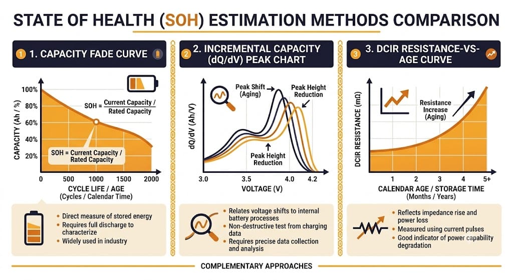
DC internal resistance (DCIR) rises as a cell ages, mostly independent of capacity fade. A DCIR-based SOH algorithm applies a known current pulse and measures the resulting voltage drop. It then calculates internal resistance using Ohm’s law, and compares that value against a baseline resistance-versus-age curve for the specific cell model.
DCIR-based SOH algorithms run faster than capacity-fade methods, since a short current pulse is enough — no full cycle required. This makes them useful for spotting outlier cells early, often before capacity fade becomes visible.
The limitation is temperature sensitivity. DCIR shifts a lot with cell temperature. An accurate DCIR-based BMS algorithm must correct every reading against a resistance-versus-temperature-versus-age model calibrated for the exact cell in use.
SOH Algorithm Comparison
| Method | What It Measures | Update Frequency | Best For |
|---|---|---|---|
| Capacity fade tracking | Ah delivered vs. rated capacity | Once per full cycle | Systems with regular full cycles |
| Incremental capacity analysis (ICA) | dQ/dV curve shape and peak shift | Per qualifying charge segment | Distinguishing aging mechanisms, warranty claims |
| DCIR-based SOH | Internal resistance rise vs. baseline | Per current pulse (fast) | Early outlier-cell detection, partial-cycle systems |
Most premium BMS platforms combine all three algorithms: DCIR for fast, frequent checks; capacity fade tracking as the long-term anchor; and ICA for diagnostic deep-dives when a cell shows early warning signs.
3. SoP Algorithm: What BMS Algorithms Tell the Inverter
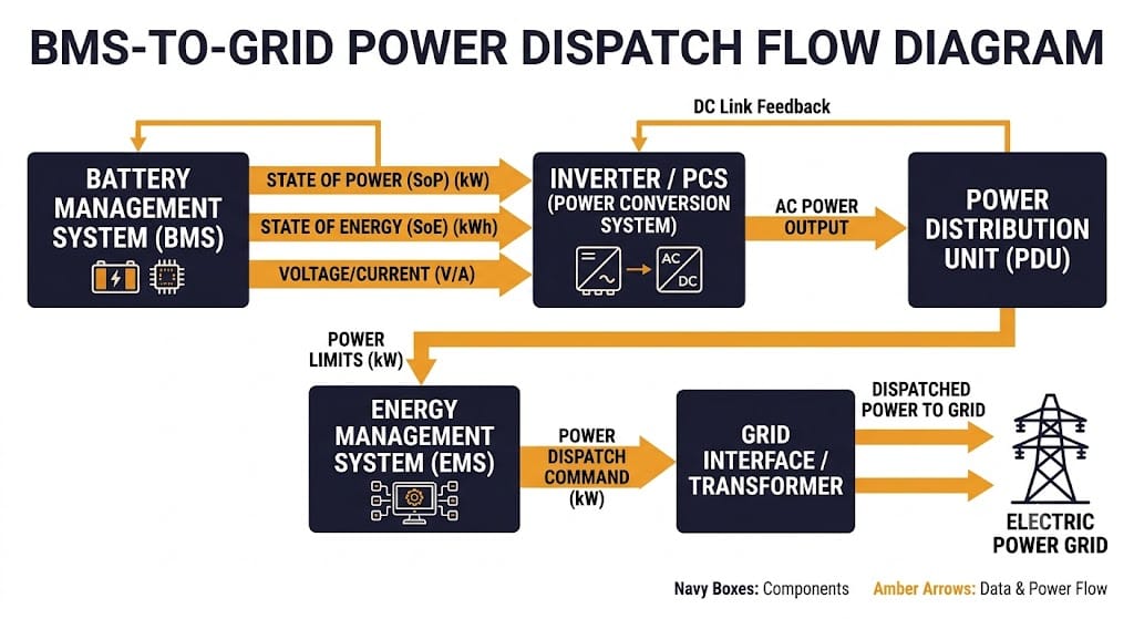
State of Power answers a different question than SOC or SOH. It asks not “how much energy is stored,” but “how much power can this pack safely deliver or accept right now.” The SoP algorithm calculates the maximum charge and discharge power available for a set time window, typically 1, 10, or 30 seconds. It weighs current SOC, temperature, cell voltage limits, and internal resistance.
This number goes straight to the inverter or PCS and to the energy management system (EMS). Without an accurate SoP algorithm, the EMS either under-dispatches or over-dispatches. Under-dispatching leaves revenue on the table during a frequency regulation or peak-shaving event. Over-dispatching triggers a protection cutoff mid-event, which is worse for grid-service contract compliance.
SoP gets harder to calculate at temperature and SOC extremes. A pack at 10% SOC or −5°C has much lower discharge SoP than the same pack at 50% SOC and 25°C, even with similar energy content. A well-designed SoP algorithm accounts for voltage sag under load. It does not rely on static cell voltage limits alone, and it uses the same internal resistance data the SOH algorithm tracks.
4. SoE Algorithm: Usable kWh, Not Just Percentage
SOC gives you a percentage. The SoE algorithm gives you the actual usable kilowatt-hours remaining. It factors in current SOH, temperature derating, and the depth-of-discharge limits set for the system. Two BESS units showing 60% SOC can have very different SoE if one has degraded to 85% SOH and the other sits near 98% SOH.
For asset owners running dispatch contracts or virtual power plant participation, SoE is the number that actually sets revenue capacity. A BMS that only reports SOC forces the EMS to apply a separate correction factor for aging, and that workaround adds error. A BMS with a proper SoE algorithm reports usable energy directly, already corrected for real-world capacity.
5. SoR and SoF Algorithms: Diagnostic and Dispatch-Readiness Checks
Two less-discussed BMS algorithms round out the state-estimation stack.
State of Resistance (SoR) tracks internal resistance as its own diagnostic metric, separate from its role as a SOH input. Rising resistance in a single string or module is often the earliest sign of an emerging fault. It can flag a loose busbar connection or accelerated local aging before it shows up in the pack-level SOH number.
State of Function (SoF) is a composite go/no-go algorithm. It combines SOC, SOH, SoP, temperature, and active fault flags into one dispatch-readiness signal. The EMS checks this signal before committing the BESS to a grid-service event. A pack can have fine SOC and SOH individually and still fail SoF — for example, if a temperature sensor reads near its fault threshold. SoF exists to stop the EMS from dispatching a unit that has energy on paper but should not be trusted for that event.
6. Cell Balancing Algorithms: Passive vs Active Control Logic
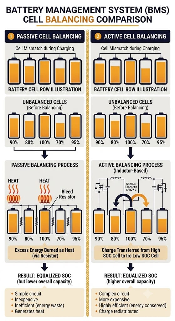
Cell balancing keeps every cell in a series string at a matched voltage and SOC. The control logic behind it is itself a BMS algorithm worth understanding, not just a hardware feature.
This balancing logic is especially vital—and complex—when dealing with the flat voltage plateaus of LFP chemistry; for a deeper look at hardware and balancing nuances there, read our specific guide on BMS for LiFePO4 batteries.
Passive Balancing Algorithm Logic
A passive balancing algorithm finds the highest-voltage cell in a string during charge. It then switches a bleed resistor across that cell, burning off excess energy as heat until the cell matches the pack average. The control logic usually triggers balancing only above a voltage or SOC threshold, commonly near the top of charge, where cell mismatch matters most for safety and full-charge capacity.
Design choices matter more than the hardware here. A poorly tuned threshold balances too aggressively, wasting energy and building unnecessary heat. Too conservative a threshold lets mismatch build up for many cycles.
Active Balancing Algorithm Logic
An active balancing algorithm moves charge from higher-voltage cells to lower-voltage cells, using inductors, capacitors, or switched-capacitor networks. It does not just burn off the difference as heat. The control logic is more complex: it must sequence several transfer paths at once, avoid oscillation between cells close in voltage, and decide when further balancing no longer justifies the switching losses.
For grid-scale BESS with thousands of series-parallel cells, the balancing algorithm’s efficiency affects round-trip efficiency and effective cycle life directly. A well-balanced pack ages its weakest cells more slowly, since those cells spend less time at voltage extremes.
7. Contactor and Isolation BMS Algorithms
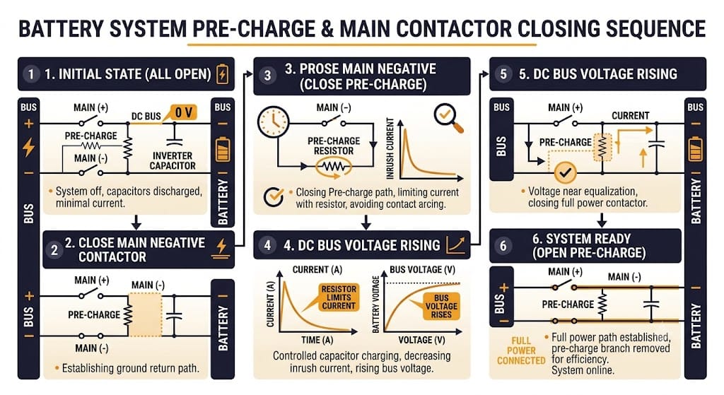
Two safety-critical BMS algorithms operate below the level most BMS content ever discusses. They matter a great deal for BESS commissioning and daily operation.
Pre-Charge Sequencing Algorithm
When a BESS connects to its inverter or DC bus, a large voltage gap between the battery and a discharged bus can spike current high enough to weld contactor contacts or blow fuses. The pre-charge sequencing algorithm closes a smaller pre-charge contactor through a current-limiting resistor first. It watches the bus voltage rise toward battery voltage, and only closes the main contactor once the gap falls within a safe threshold, typically a few percent.
The algorithm must also set a timeout and a fault response. If bus voltage fails to rise as expected in time, that signals a downstream fault. A well-designed sequence aborts the connection instead of forcing the main contactor closed anyway.
Isolation Monitoring Algorithm
High-voltage BESS strings must stay electrically isolated from chassis ground. The isolation monitoring algorithm injects a small test signal, or measures leakage current, between the HV bus and chassis ground. It then calculates an isolation resistance value. A common safety threshold is 500 ohms per volt of system voltage — a 750V BESS string needs at least 375,000 ohms of isolation resistance under this rule.
A slowly degrading isolation reading, even one still above the fault threshold, is an early warning worth flagging. It usually points to moisture ingress, insulation wear, or a developing ground fault well before it trips a hard fault.
8. Safety Diagnostic Algorithms: MAVD, RdV, and Early Fault Detection
Beyond voltage, current, and temperature thresholds, advanced BMS platforms run pattern-based diagnostic algorithms. These catch failure modes before they reach a hard safety limit.
Maximum Allowable Voltage Deviation (MAVD) algorithms compare each cell’s voltage against the pack average in real time. A cell drifting outside its expected deviation band can signal an internal short, a connection fault, or local degradation — even while it stays within absolute safe voltage limits. Because MAVD looks at relative deviation, not absolute thresholds, it often catches faults earlier than simple over-voltage or under-voltage protection.
Resistance-derivative or rate-of-change (RdV) algorithms track how fast a cell’s voltage or resistance is changing, not just its current value. A cell with rapidly climbing resistance is a different risk than one with stable but elevated resistance, even if both report the same SOH today. RdV algorithms flag the rate of change itself as its own alarm condition.
These diagnostic layers matter most for large-format BESS, where a single degrading cell among thousands can go unnoticed until it causes a string-level fault. Standards bodies such as the IEC publish safety requirements for stationary lithium battery systems that reference exactly this kind of deviation monitoring.
Furthermore, if you are deploying assets in the European market, these algorithmic diagnostics are critical for compliance; see our EU batteries regulation EU 2023 1542 complete guide for a full breakdown of the data and safety mandates.
Ask suppliers whether their BMS runs deviation and rate-of-change diagnostics on top of standard threshold protections — this is a real differentiator between a basic BMS and a genuinely safety-engineered one.
9. RUL Prediction Algorithms and Second-Life Value
Remaining Useful Life algorithms take SOH trend data and project forward. They estimate how many more cycles or years remain before the pack falls below an end-of-life threshold, commonly 70–80% of original capacity.
Three RUL Algorithm Approaches
Empirical RUL algorithms fit a degradation curve — often exponential, or a two-stage linear-then-accelerating shape — to historical SOH data for the specific chemistry and use profile. They then extrapolate forward. These are cheap to run and reasonably accurate for well-studied LiFePO4 chemistries with large datasets for a quick way to model these degradation curves yourself based on cycle depth and temperature, you can check out our interactive battery cycle life calculator. But they assume future use resembles the past.
Physics-based (electrochemical) RUL algorithms simulate the degradation mechanisms directly: lithium plating, SEI growth, active material loss. They predict RUL from first principles. These are more accurate under changing use conditions, but they need detailed cell-level parameters that cell suppliers do not always share.
Machine-learning RUL algorithms train on large fleets of historical degradation data. They predict RUL from current sensor patterns without an explicit physical or empirical formula. These can beat both other approaches when trained on a large enough fleet of the same cell type and use case. But they need a lot of historical data, and they can behave unpredictably outside the conditions they trained on.
Why RUL Algorithm Accuracy Matters for BESS Economics
RUL accuracy affects two commercial decisions directly: warranty reserve calculations for suppliers, and second-life asset valuation for owners. A BESS pack projected to hold 80% capacity for ten more years is worth much more on the second-life market than one with an uncertain or steeply declining RUL curve. Lower-demand second-life uses, like residential backup or slow-cycling grid support, depend on that projection being credible.
For utility-scale BESS operators planning eventual asset disposition, ask your BMS or EMS supplier which RUL modeling approach they use, and what fleet data backs it. Battery aging research from national labs such as NLR (National Laboratory of the Rockies) increasingly informs these models. Ask whether RUL confidence intervals are reported alongside the point estimate — a single RUL number with no range is hard to use for financial planning.
10. Questions to Ask Your BMS Supplier About Algorithms
Marketing language often claims “advanced algorithms” without saying which ones actually run in firmware. For a structured framework on auditing these capabilities during procurement, see our guide on BESS supplier BMS evaluation.
The following targeted questions will help you separate real algorithmic depth from a basic protection-only BMS with technical-sounding labels:
- Which SOH algorithm does the BMS use — capacity fade tracking, ICA, DCIR-based, or a combination? A BMS that only runs capacity fade tracking will be slow to catch outlier cells in systems that rarely complete full cycles.
- Does the BMS calculate SoP and SoE algorithms, or only SOC and SOH? Without SoP output, the EMS must apply conservative blanket power limits, which lowers dispatch revenue.
- What isolation resistance threshold does the algorithm enforce, and how is it temperature- and time-compensated? A static threshold with no trend monitoring misses slow isolation decay.
- Does the balancing algorithm run passive, active, or both, and what triggers a balancing cycle? Ask for the specific voltage or SOC threshold, not just “the BMS balances cells.”
- What RUL algorithm approach is used, and is a confidence interval reported? A point-estimate RUL number with no uncertainty bounds has limited use for financial and warranty planning.
Conclusion: Algorithm Depth Is the Real BMS Differentiator
SOC estimation gets most of the attention in BMS marketing. But the BMS algorithms that actually protect a BESS investment over its 10–20 year life sit one layer deeper. SOH tracking catches aging mechanisms early. SoP and SoE outputs maximize safe dispatch revenue. Balancing logic gets tuned for the specific pack architecture. Safety diagnostics catch deviation before it becomes a fault. RUL models come with defensible confidence intervals.
When you evaluate a BMS or a BESS supplier, ask specifically which of these BMS algorithms are implemented, and how they were validated. Do not settle for “the BMS monitors SOC and SOH.” The answer reveals whether you are buying genuine algorithmic engineering or a basic protection circuit with confident marketing copy.
| ☀️ Need a BMS Algorithm Review for Your BESS Project? Sunlith Energy reviews BMS algorithm implementations — SOH methodology, SoP/SoE accuracy, balancing logic, and RUL modeling — for BESS projects from 50 kWh upward. Contact us before you commit to a supplier. |
Frequently Asked Questions About BMS Algorithms
What algorithms does a BMS run besides SOC estimation?
A production BMS runs several algorithms beyond SOC: SOH estimation (capacity fade tracking, incremental capacity analysis, or DCIR-based methods), SoP and SoE calculations, cell balancing control logic, contactor pre-charge sequencing, isolation monitoring, safety diagnostics such as voltage-deviation and resistance-rate-of-change monitoring, and often RUL prediction models.
What is the difference between the SOH and SoP algorithms in a BMS?
The SOH algorithm measures how much capacity and performance a battery has lost compared to new, shown as a percentage. The SoP algorithm measures how much power the battery can safely deliver or accept right now, based on current SOC, temperature, and internal resistance. SOH looks backward at cumulative aging. SoP looks at the immediate power ceiling for dispatch decisions.
Why does the SoP algorithm matter for BESS dispatch even if SOC looks fine?
A pack can show good SOC while still having a low SoP at cold temperatures or high internal resistance. That means it cannot deliver the power a grid-service event needs without tripping a voltage protection limit. An EMS that only checks SOC before dispatch risks committing to an event the pack cannot actually support.
How does the DCIR-based SOH algorithm work?
The BMS applies a known current pulse and measures the resulting voltage drop. It calculates internal resistance using Ohm’s law, then compares that resistance against a temperature-compensated baseline curve for the specific cell model. This algorithm runs faster than capacity-fade tracking, since it needs no full charge-discharge cycle.
What is a good RUL algorithm confidence level for a utility-scale BESS?
There is no single universal number — it depends on the modeling approach and available fleet data. What matters more is whether the supplier reports a confidence interval at all, rather than a single point estimate, and whether the model has been checked against real fleet degradation data for the same cell chemistry and use profile.
Do I need an active balancing algorithm for a grid-scale BESS, or is passive enough?
Passive balancing works fine for many commercial and lower-cycling systems. For utility-scale BESS with high cycling frequency and large series strings, an active balancing algorithm usually improves round-trip efficiency and cuts accelerated aging in weaker cells. That can justify its added cost over the system’s lifetime.
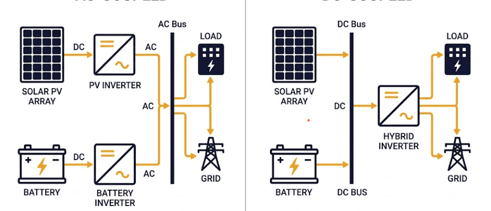
AC-Coupled vs DC-Coupled BESS: Which Architecture Is Right for Your Project?
AC-coupled vs DC-coupled BESS is one of the first choices you’ll face in any solar-plus-storage project. This one decision shapes your system’s efficiency, cost, and how easily you can expand it later. Both architectures store solar energy in a battery for later use. But they connect the battery in different places relative to the inverter, and that single design choice ripples through nearly every other spec on the system. This guide walks through the differences so you can pick the right fit.
What Is AC-Coupled BESS?
An AC-coupled BESS connects the battery to the grid through its own dedicated inverter. This component sits separate from the solar PV inverter. Power from PV and power from the battery meet on the AC side of the system rather than sharing a DC bus. This makes AC-coupled storage the more common choice when you’re adding a battery to solar you already have running. For the full breakdown of components and operation, see What is AC Coupled BESS?.
What Is DC-Coupled BESS?
A DC-coupled BESS connects the battery and the solar PV array on the same DC bus, ahead of a single shared inverter. Because both share one conversion path, DC-coupled systems typically post better round-trip efficiency and lower equipment costs, at the expense of retrofit flexibility. For the full architecture and step-by-step operation, see What is DC Coupled BESS?.
AC-Coupled vs DC-Coupled BESS: Side-by-Side Comparison
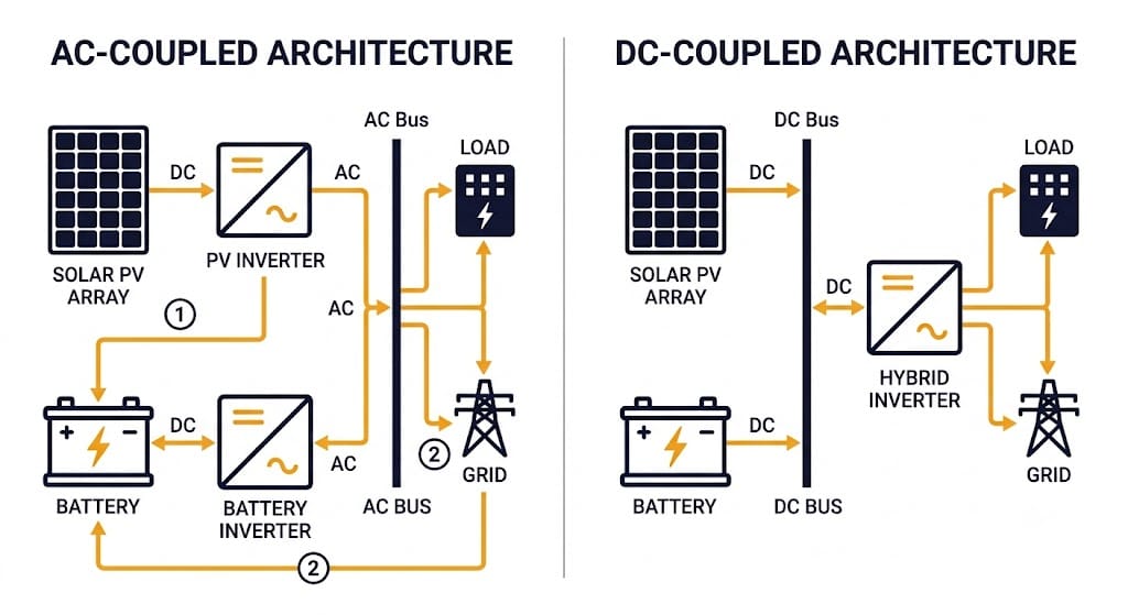
Here’s the AC-coupled vs. DC-coupled BESS comparison at a glance — the factors that matter most when you design a solar-plus-storage system:
| Factor | AC-Coupled BESS | DC-Coupled BESS |
| Connection point | Battery connects via its own inverter on the AC side | Battery and PV share one DC bus, ahead of a single inverter |
| Inverters required | Two — one for PV, one for battery | One shared hybrid inverter |
| Conversion stages | Multiple DC-AC-DC conversions on some charge paths | Single DC-to-AC conversion for grid/load power |
| Round-trip efficiency | Lower — extra conversion stages add losses | Higher — fewer conversion losses |
| Balance-of-system cost | Lower than standalone, but higher than DC-coupled (separate inverters, switchgear) | Lowest of the three — shared inverter and BOS hardware |
| Best for | Retrofitting storage onto existing solar | New-build, greenfield solar-plus-storage projects |
| Solar charging during outage | Depends on inverter design; may need extra hardware | Typically yes, in most configurations |
| Curtailment / clipping capture | Limited — PV inverter still governs PV output | Can capture otherwise-clipped PV energy behind a higher-ILR array |
| Grid response speed | Slower — control system coordinates multiple inverters | Faster — single inverter, more direct control path |
| Future expansion | Easier — PV and storage can be sized/upgraded independently | Harder — added battery capacity must match existing DC bus voltage |
No single architecture wins on every factor. The right choice depends on your project type and how much you weigh upfront cost against long-term efficiency.
AC-Coupled vs DC-Coupled BESS: Efficiency Compared
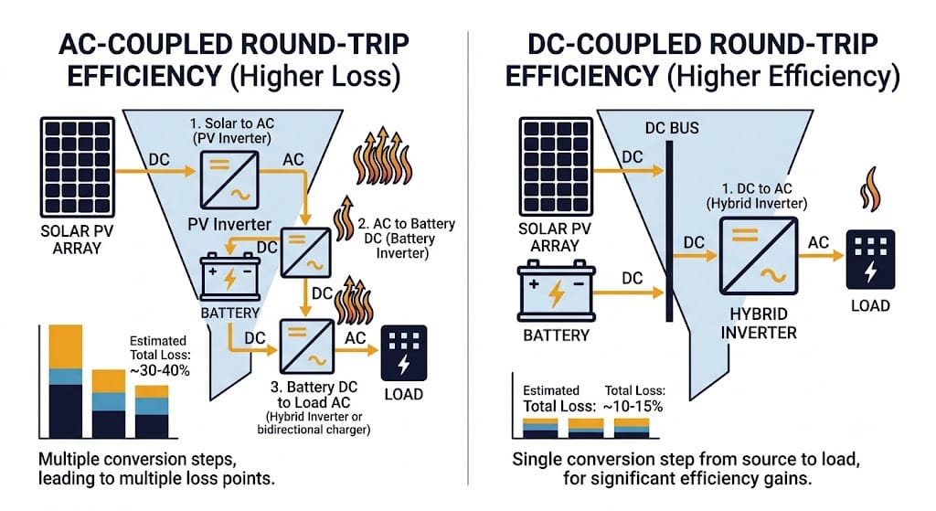
Every DC-to-AC conversion wastes some energy as heat. An AC-coupled system can convert PV energy to AC, then back to DC to charge the battery, then to AC again when you use it. That’s up to three conversion stages on some charge paths.
A DC-coupled system skips most of that. It charges the battery straight from the DC bus and converts to AC only once, when you actually need AC power. This is the core reason DC-coupled architectures tend to post higher round-trip efficiency in side-by-side testing.
We break down the exact numbers in AC vs DC Round Trip Efficiency in Battery Energy Storage Systems, and show you how to calculate round-trip efficiency for your own project in our BESS Round Trip Efficiency guide.
AC-Coupled vs DC-Coupled BESS: Cost Compared
Both architectures cost less than siting solar and storage separately. DC-coupled systems generally cost less than AC-coupled ones on new-build projects, too.
The U.S. Department of Energy’s Solar-Plus-Storage 101 resource confirms this pattern: co-locating PV and storage on the same site cuts system cost compared to siting them separately, whether you choose AC-coupled or DC-coupled. Most of the savings come from shared balance-of-plant infrastructure.
DC-coupled designs push those savings further. They eliminate a full second inverter and its switchgear. That said, retrofit constraints can narrow this advantage — if AC-coupling is your only practical option, the smaller cost gap may not matter much.
Retrofit vs. Greenfield: Matching Architecture to Project Stage
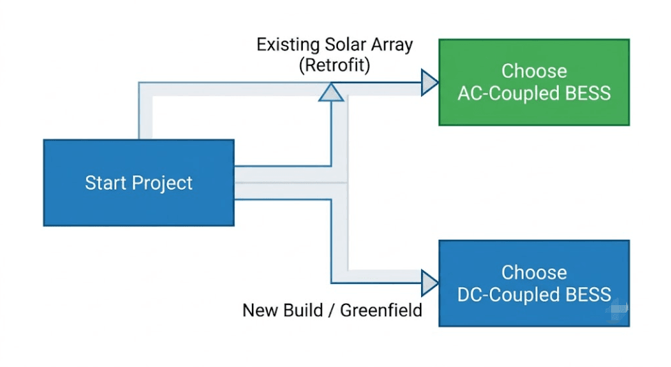
Project stage often decides the outcome before cost or efficiency even enter the conversation.
If you already run solar, adding a DC-coupled battery means tying into the existing DC bus and matching its voltage. That’s technically possible, but it usually means replacing or reconfiguring your existing inverter. AC-coupled storage sidesteps that problem entirely — the battery gets its own inverter and connects on the AC side, so your existing solar installation stays untouched.
New-build, greenfield projects don’t face that constraint, since you design PV and storage together from day one. That’s why DC-coupled architectures dominate new utility-scale and C&I builds. In the end, this AC-coupled vs. DC-coupled BESS decision usually comes down to one question: are you retrofitting, or building new?
When to Choose AC-Coupled BESS
- Adding storage to solar you already have running
- Projects where you need to size, optimize, or replace PV and battery independently
- Sites where minimizing changes to existing PV wiring and permits matters
- Phased projects that add storage well after the solar installation
- Systems needing simpler expansion of storage capacity over time
When to Choose DC-Coupled BESS
- New solar-plus-storage builds where you design PV and storage together from the start
- Utility-scale and C&I projects prioritizing round-trip efficiency
- Microgrid and off-grid systems needing solar charging during outages
- High inverter-loading-ratio PV arrays looking to capture otherwise-clipped energy
- Projects where minimizing equipment count and balance-of-system cost is a priority
AC-Coupled vs DC-Coupled BESS: Trade-offs to Weigh
Efficiency and cost aren’t the only variables to weigh.
DC-coupled systems can be harder to expand later. Additional battery capacity generally needs to match the voltage of your existing DC bus. The tighter integration between PV and storage also means a fault on one side can affect the other.
AC-coupled systems avoid that coupling risk and expand more easily. You pay for that flexibility with two inverters, two sets of switchgear, and a somewhat slower response to fast grid commands like frequency regulation, since the control system has to coordinate multiple inverters instead of one.
Weigh these trade-offs against your project’s timeline, budget, and growth plans. That usually beats picking the ‘better’ architecture in the abstract.
Can You Combine AC-Coupled and DC-Coupled BESS?
Some projects don’t have to choose only one. A hybrid architecture can pair DC-coupled storage on a new PV block with an existing AC-coupled asset elsewhere on-site. Or it can phase in DC-coupled storage over multiple project stages. You’ll see this more often on larger utility-scale sites with modular BESS designs. For a broader look at how AC-coupled, DC-coupled, modular, and hybrid designs fit together, see our guide to Understanding Energy Storage System BESS Architectures.
Frequently Asked Questions
Here are quick answers to the AC-coupled vs DC-coupled BESS questions we hear most often:
What is the main difference between AC-coupled and DC-coupled BESS?
AC-coupled systems use two separate inverters — one for solar PV and one for the battery. DC-coupled systems share a single inverter. PV and battery connect to the same DC bus before the system converts power to AC.
Which is more efficient, AC-coupled or DC-coupled BESS?
DC-coupled BESS is generally more efficient because energy converts from DC to AC only once. AC-coupled systems often involve extra conversion stages, especially when charging the battery from solar, and that raises round-trip losses.
Is AC-coupled or DC-coupled BESS cheaper?
DC-coupled systems typically cost less on the balance-of-system side, since they need only one inverter and one set of switchgear. AC-coupled systems cost more upfront, but you can add them incrementally, which sometimes offsets the gap on retrofit projects.
Can I add a DC-coupled battery to an existing solar system?
You can, but it’s more complex than AC-coupling. The battery must connect to the existing DC bus and match its voltage. For most retrofits, AC-coupled storage is the simpler, more common approach.
Does DC-coupled BESS work off-grid?
Yes. DC-coupled architectures generally support off-grid and islanded operation. They can keep charging from solar during a grid outage, which makes them a common choice for microgrid and remote projects.
Why do DC-coupled systems capture more solar energy?
In a DC-coupled system, the battery can charge directly from PV output that would otherwise get clipped when the inverter loading ratio exceeds 1. That’s because the battery sits on the DC side, before the inverter’s AC output limit applies.
Is there a hybrid option that combines AC and DC coupling?
Yes. Some larger projects use a hybrid architecture that pairs DC-coupled storage with an existing AC-coupled asset, or phases DC-coupled storage in over time. You’ll see this more often on utility-scale sites with modular BESS designs.
AC-Coupled vs DC-Coupled BESS: Final Verdict
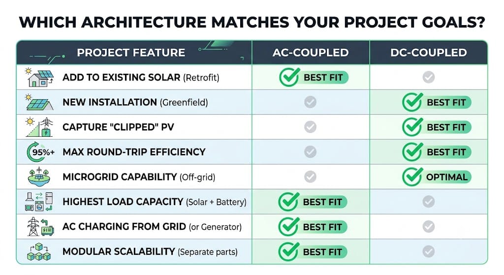
AC-coupled and DC-coupled BESS both store solar energy for later use, but they get there differently. That difference shows up in efficiency, cost, and how easily the system grows over time.
AC-coupled storage stays the more flexible choice for retrofits and phased projects. DC-coupled architectures tend to win on efficiency and cost for new-build solar-plus-storage systems. The right call comes down to where your project starts, not which architecture is objectively ‘better’.
Whichever direction fits your project, the Sunlith Energy team can help size and specify the right BESS architecture, PCS, and battery configuration for your site.

BESS Oversizing: Pros, Cons & the Right-Sizing Strategy for Your Project
BESS oversizing — deliberately installing more nameplate energy capacity than your immediate load demands — is one of the most debated decisions in battery storage project design. Therefore, getting this decision right has direct consequences for project ROI, battery longevity, and contracted performance guarantees. Furthermore, as storage markets mature and the Section 48E Investment Tax Credit continues to reshape project economics, understanding when BESS oversizing helps and when it hurts has never been more important.
In this guide, we break down the real pros and cons of BESS oversizing across residential, commercial and industrial (C&I), and utility-scale applications. Additionally, we provide a practical sizing framework, a direct comparison with the augmentation alternative, and clear guidance on how much oversizing is appropriate for each use case. For background on key BESS performance metrics, see our BESS specifications guide.
| Key Takeaway BESS oversizing reduces average depth of discharge, extends cycle life, and provides a degradation buffer — but it carries real costs in capex, idle capacity, and calendar aging risk. Consequently, the right answer depends entirely on your use case, load profile, battery chemistry, and project economics. |
What Is BESS Oversizing? Definition and Key Drivers
BESS oversizing means installing more nameplate energy capacity (kWh) or power capacity (kW) than the system is expected to dispatch on a daily basis under normal operating conditions. In other words, it is the deliberate act of selecting a battery system larger than the immediate load or solar coupling requirement.
The Four Main Reasons Projects Choose BESS Oversizing
Project developers and system designers choose BESS oversizing for four primary reasons. First, it provides a built-in degradation buffer — batteries lose capacity over time, so installing extra kWh upfront ensures the system still meets its contractual output at end of life (EOL). Second, it reduces the average depth of discharge (DoD), which significantly reduces electrochemical stress and extends cycle life. Third, it future-proofs the system against load growth — a facility adding EV chargers or expanding solar may outgrow a precisely sized BESS within three to five years. Finally, the ITC captures a larger credit on the full installed capacity at commissioning rather than on augmented modules added later.
Note: Before looking at buffers, make sure you’ve calculated your exact day-one minimum requirements using our Energy Storage Sizing & Calculation Guide.
BESS Oversizing vs Augmentation: Two Different Strategies
It is important to separate two strategies that are frequently conflated: oversizing (installing more capacity upfront) and augmentation (adding capacity later). Both address the degradation problem, but they carry very different economic and technical profiles. Whereas oversizing locks in capex on Day 1, augmentation defers cost — but at the risk of losing ITC eligibility on the additional modules. We explore this comparison in detail in Section 5.
Pros of BESS Oversizing: 7 Technical and Financial Benefits
1. Extended Cycle Life Through Lower Depth of Discharge
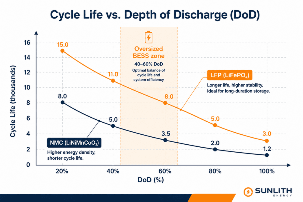
The single most significant technical benefit of BESS oversizing is the reduction in average Depth of Discharge (DoD). Battery cycle life is acutely sensitive to DoD: a LiFePO4 (LFP) cell discharged to 80% DoD typically delivers 3,000–6,000 cycles to 80% capacity retention, whereas the same cell cycled at 40% DoD can exceed 10,000 cycles. Moreover, for NMC chemistry, the spread is even wider. Therefore, oversizing directly reduces the daily DoD, keeping cells in the shallow-cycle, high-longevity operating zone. As a result, the total useful life of the system increases substantially — without any hardware change.
A peer-reviewed sizing study published in MDPI Energies confirmed that an oversized BESS consistently operates at approximately 30% DoD, significantly reducing cycling degradation compared to a precisely sized system. See our BESS cycle life comparison guide for detailed 0.5C vs 1C cycling data across liquid-cooled LFP formats.
2. Built-In Degradation Buffer for End-of-Life Performance
All BESS contracts and revenue agreements are written against end-of-life capacity, not nameplate. Consequently, a project designed to deliver 1 MWh at year 10 must either oversize at commissioning to absorb predicted capacity loss, or augment mid-life. BESS oversizing solves this directly: the 15–20% extra capacity at year 0 becomes the system’s normal operating capacity at year 8–10, after degradation has run its course. In addition, oversizing also enables developers to lock in capital expenditures at project outset, mitigating future cost uncertainty. For a deeper understanding of capacity fade mechanics, see our Battery State of Health (SoH) estimation guide.
3. Improved Round-Trip Efficiency at Partial Loads
Battery inverters and Power Conversion Systems (PCS) operate most efficiently when working well below their rated power ceiling. Therefore, an oversized BESS means the power electronics run at partial load more often, reducing switching losses and thermal stress. Across LFP systems, round-trip efficiency (RTE) typically reaches 90–95% in well-managed partial-load conditions versus 85–88% when the system is pushed to rated limits daily. Furthermore, professional system sizing guidelines recommend oversizing by 5–20% specifically to compensate for RTE losses over the project’s lifetime. For a full breakdown of how RTE impacts your PCS selection, visit our BESS PCS functions and features guide.
4. Future-Proofing for Load Growth
Commercial and industrial facilities are rarely static. An EV fleet charging infrastructure build-out, a new production line, additional HVAC loads, or expanded solar capacity can all push a precisely sized BESS into insufficiency within a few years. As a result, BESS oversizing provides headroom to absorb load growth without a full system redesign or costly inverter upgrades. For residential customers, similarly, oversizing by 10–20% accounts for future appliance electrification — heat pumps, EV charging, induction cooking — that increase household energy consumption over time. This is especially relevant given that electricity rates have increased 32% over the past decade and the trend is expected to continue.
5. Greater Resilience During Extended Outages
An oversized BESS provides substantially longer backup durations during grid outages. For instance, where a precisely sized system may sustain critical loads for 4–6 hours, a 25% oversized system of the same power rating extends that window to 5–7.5 hours without additional hardware. Consequently, for hospitals, data centres, manufacturing facilities, and off-grid microgrids, this resilience buffer is a core design requirement rather than an optional feature. In addition, BESS oversizing enables higher solar self-consumption ratios, because the system can absorb more excess PV generation that would otherwise be curtailed — especially in DC-coupled configurations. Our cylindrical vs prismatic LFP cell guide covers how cell format selection interacts with resilience design.
6. Tax Credit Maximisation Under Section 48E
Under the Section 48E Clean Electricity Investment Tax Credit, the ITC applies to the full installed nameplate capacity at commissioning. Projects beginning construction before 2033 can qualify for a base credit of 6% rising to 30% — or up to 50% with domestic content and labour standards — on the entire installed system. Therefore, oversizing at commissioning rather than augmenting later allows developers to capture ITC on the additional capacity now, when the credit is at its most generous. As documented by Energy-Storage.News, Pivot Energy uses optimisation models specifically to find the ‘sweet spot’ where overbuilding by 15–20% captures the full ITC while also reducing DoD and slowing the degradation curve.
7. Higher Solar Self-Consumption and Clipping Capture
In solar-plus-storage configurations, an oversized BESS absorbs more excess PV generation that would otherwise be curtailed — particularly in DC-coupled systems where the battery captures inverter clipping losses. Projects with aggressively sized solar arrays consequently benefit most from an oversized storage buffer, enabling higher self-consumption ratios and better time-of-use (ToU) arbitrage revenue. Additionally, the flat voltage profile of LFP cells means the battery can accept charge across a wider SoC range without significant efficiency loss, making it well-suited to absorbing variable clipping events.
Cons of BESS Oversizing: 7 Real Drawbacks to Weigh
1. Higher Upfront Capital Expenditure
The most obvious downside of BESS oversizing is cost. At current commercial LFP BESS pricing of $220–$320 per kWh (nameplate, installed), adding 15–25% extra capacity translates directly into a 15–25% larger capital outlay. For example, on a 1 MWh C&I project, the oversizing premium reaches $33,000–$80,000. On a 10 MWh utility-scale project, the figure climbs to $330,000–$800,000. As a result, higher capex extends payback periods, dilutes IRR, and increases financing costs. Moreover, the 20/80 rule for battery SoC management — explored in our 20/80 rule for batteries guide — shows that moving from a 90% DoD strategy to a strict 60% DoD strategy for the same usable energy requires installing roughly 33% more nameplate capacity, at a steep capex premium.
2. Idle Capacity — Stranded Capital
An oversized BESS, by definition, contains capacity that is not used every day. In a system with a 30% oversizing factor, approximately 23% of the installed kWh is functionally stranded under normal operating conditions — generating no direct revenue, not contributing to peak shaving, and not offsetting grid draw. Therefore, for merchant revenue projects where every kWh of contracted discharge must justify its hardware cost, idle capacity directly weakens the financial case. Consequently, a detailed financial model comparing oversized vs precisely sized scenarios is essential before committing to an aggressive oversizing strategy.
3. Calendar Aging at High State of Charge
There is a subtle but real risk in BESS oversizing: a battery that is rarely deeply discharged will consequently spend more time at a high state of charge (SoC) between cycles. For LFP, this matters less due to the flat voltage curve, but for NMC and NCA chemistries, sustained high SoC accelerates calendar aging through lithium plating and electrolyte decomposition. The EMS must therefore be configured with SoC upper limits (typically a 90% ceiling) to mitigate this risk, which further reduces the usable window — partially negating the oversizing benefit.
4. Larger Physical Footprint and Permitting Complexity
A larger BESS means more rack space, additional container units, larger electrical rooms, and more complex fire suppression under NFPA 855 setback requirements. For urban C&I projects, rooftop installations, or sites with constrained footprints, BESS oversizing may simply not be feasible without additional civil and structural engineering. As a result, the incremental cost of accommodating a larger system can erode or eliminate the economic benefit of the additional capacity.
5. Risk of Over-Engineering Against Inaccurate Load Projections
BESS oversizing is typically justified by load growth projections that may not materialise. A facility forecasting 30% energy consumption growth over five years but actually growing 10% has paid a significant capex premium for capacity that will never be fully utilised. Furthermore, the further into the future the projections extend, the less reliable they become — and the weaker the economic case for aggressive oversizing. Therefore, right-sizing discipline, grounded in real interval load data, is essential before committing to an oversizing strategy.
6. Interconnection Limit Conflicts
Utility interconnection agreements define the maximum allowable power at the Point of Common Coupling (PCC). An oversized BESS that exceeds the permitted inverter or PCS rating — or that pushes a project over the interconnection ceiling — may require expensive distribution upgrades, transformer replacements, or grid impact studies. As a result, always validate that the oversized system’s power rating remains within interconnection constraints before finalising the design.
7. Diminishing Returns on ROI for Thin-Margin Projects
For projects where the economics are already marginal — low ToU spreads, limited demand charges, or thin merchant power prices — the additional capex of BESS oversizing may not be recoverable within the project’s financial life. Therefore, a right-sizing discipline, rather than aggressive oversizing, often produces better risk-adjusted returns on projects operating in challenging market conditions. Additionally, if battery prices continue to fall, augmentation at year 5–7 may deliver the same EOL capacity guarantee at a lower total lifecycle cost than oversizing today.
BESS Oversizing Pros and Cons: Quick-Reference Comparison Table
| PROS of BESS Oversizing | CONS of BESS Oversizing |
| Extends cycle life by reducing average DoD | Higher upfront capital expenditure |
| Slower capacity degradation over project lifetime | Idle capacity — underutilised asset |
| Buffer for future load growth without re-powering | Larger footprint and space requirements |
| Improves round-trip efficiency at partial loads | Additional BMS / thermal management complexity |
| Strengthens resilience during extended outages | Risk of battery sitting at high SoC, accelerating calendar aging |
| Lock in ITC / 48E tax credits on full capacity now | Diminishing returns if load growth projections are wrong |
| Reduces depth of discharge and thermal stress | Potentially overshoots interconnection limits |
| Supports higher solar self-consumption | Makes ROI harder to justify on thin-margin projects |
BESS Oversizing vs Augmentation: Which Degradation Strategy Wins?
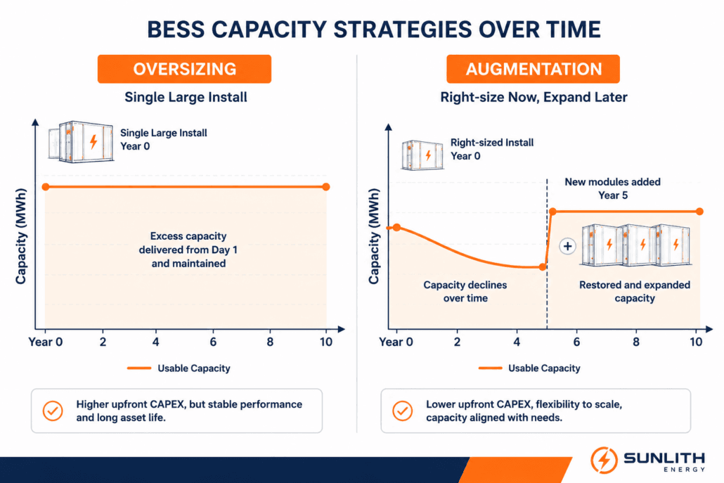
The BESS oversizing debate is inseparable from its primary alternative: augmentation — the strategy of adding battery modules at year 5 or 7 to restore degraded capacity. However, these strategies are not equivalent, and the right choice depends on several project-specific factors.
| Factor | BESS Oversizing (Upfront) | Augmentation (Mid-Life) |
| Capex Timing | Higher Day-1 cost; lower total lifecycle cost | Lower Day-1 cost; uncertain future capex at year 5–7 |
| ITC Eligibility | Full credit on entire capacity at commissioning | Augmented capacity may miss ITC or face FEOC risk |
| Degradation Benefit | Reduces DoD and slows degradation from Day 1 | Addresses degradation after it has occurred |
| Space Planning | Must install full footprint upfront | Must reserve physical and electrical space for future modules |
| Falling Battery Prices | Locks in today’s cost for future capacity | May benefit from lower prices at year 5 |
| Complexity | Lower operational complexity | Requires mid-project procurement and system rebalancing |
| Best For | Utility-scale; ITC-sensitive projects; stable load forecasts | C&I with budget constraints; markets with falling storage prices |
As battery prices continue to fall, augmentation is becoming more attractive for some project types. Nevertheless, as Pivot Energy’s modelling demonstrates, for ITC-sensitive projects, oversizing by 15–20% upfront typically produces better risk-adjusted NPV than augmentation — particularly given the difficulty of qualifying augmented capacity for the same ITC rate under the One Big Beautiful Bill Act.
How Much BESS Oversizing Is Right? A Use-Case Sizing Guide
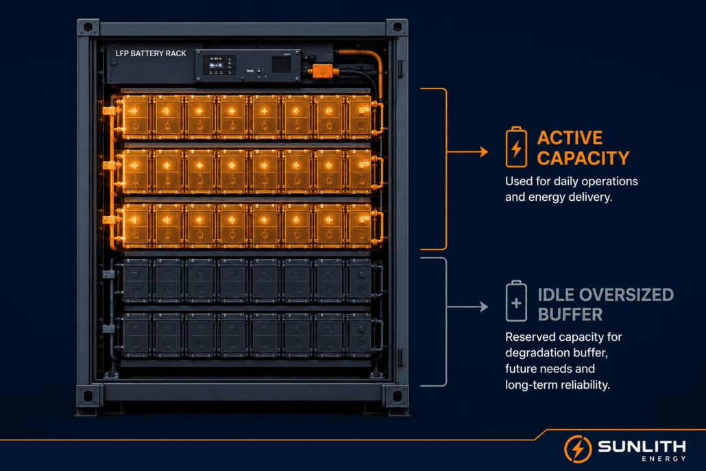
There is no universal BESS oversizing percentage. Instead, the right buffer depends on your use case, battery chemistry, load profile, and project economics. However, the table below provides a practical reference framework covering the most common project types:
| Use Case | Recommended BESS Oversizing | Rationale | Key Risk if Under-Sized |
| Residential Solar + Storage | 10–20% | Compensate for DoD and RTE losses; buffer seasonal variation | Shortfall on multi-day cloudy periods |
| C&I Peak Shaving | 15–25% | Cover end-of-life (EOL) capacity guarantee; avoid demand charge spikes | Missed peak shaving events at year 8–10 |
| Off-Grid / Microgrid | 20–30% | Autonomy days require deep reserve; no grid backup available | Load shedding during contingency events |
| Utility-Scale / Grid Services | 10–20% (overbuild) | Reduces average DoD; locks in ITC on full nameplate capacity | Degradation causes contract shortfalls |
| Solar Clipping Capture | 5–15% on storage side | Capture otherwise-curtailed DC energy during peak irradiance | Revenue loss from curtailed generation |
The BESS Sizing Formula: Starting Point Before Oversizing
Before applying any BESS oversizing factor, establish your baseline required capacity using the standard sizing formula:
| Battery Sizing Formula Required Capacity (kWh) = (Daily Load × Autonomy Days) ÷ (DoD × Round-Trip Efficiency) Example: 30 kWh/day load × 2 autonomy days = 60 kWh base ÷ 0.85 DoD × 0.92 RTE = 76.6 kWh nameplate minimum + 15% degradation buffer = approximately 88 kWh recommended nameplate capacity Note: For LFP chemistry with a 90% DoD operating window, adjust DoD factor accordingly. |
For LFP chemistry specifically, the degradation benefit of BESS oversizing is more modest than for NMC or NCA, because LFP already exhibits a flatter voltage curve and superior cycle life at high DoD. Therefore, the most rigorous approach — as recommended in NREL’s Energy Storage Modelling guidelines and the IEA’s Batteries and Secure Energy Transitions report — is to use simulation tools such as NREL’s SAM or PVsyst with real 15-minute interval load data to determine the optimal capacity that minimises LCOE while meeting the contracted capacity guarantee at EOL.
Does Battery Chemistry Change the BESS Oversizing Calculus?
Yes — significantly. However, the extent to which BESS oversizing is beneficial varies considerably by chemistry. Here is how the most common BESS chemistries interact with oversizing strategy:
LFP (LiFePO4): The Most Common Choice for Commercial BESS
LFP already offers exceptional cycle life — 6,000–10,000+ cycles at 0.5C to 80% SoH — a flat voltage curve that reduces SoC-related aging, and thermal stability above 270°C. Therefore, the benefit of BESS oversizing for LFP is real but more modest than for NMC. A 10–15% oversizing factor is typically sufficient for residential and C&I LFP projects, unless extended autonomy is a primary requirement. For a detailed comparison of LFP cell formats, see our cylindrical vs prismatic LFP guide.
NMC (Nickel Manganese Cobalt): Greater Benefit from Oversizing
NMC cells are more sensitive to both high SoC and high DoD. The cycle life penalty for deep discharging is steeper, and calendar aging at high SoC is more pronounced. Consequently, for NMC-based systems, BESS oversizing by 20–30% can provide meaningful cycle life extension. However, the EMS must be configured to avoid sustained high-SoC parking, which otherwise accelerates precisely the degradation the oversizing was intended to prevent.
NCA (Nickel Cobalt Aluminium): Strongest Case for Oversizing
NCA is even more sensitive to DoD extremes than NMC. Therefore, BESS oversizing is strongly recommended for NCA systems, alongside strict SoC window management — typically a 20–90% operational band. As a result, NCA-based utility-scale systems frequently carry 20–30% oversizing factors as a standard design requirement.
When to Choose BESS Oversizing — and When to Avoid It
Oversize Your BESS When These Conditions Apply
- Your project carries a 10+ year contract or PPA with capacity guarantee provisions that must be met at end of life
- You are qualifying for ITC / Section 48E and want to maximise the tax credit on the full installed capacity at commissioning
- The site has a clear load growth trajectory — EV charging, electrification roadmap, or solar expansion planned
- You are designing an off-grid or critical backup system where autonomy days are non-negotiable
- NMC or NCA chemistry is specified and DoD reduction delivers a significant cycle life benefit
- Your DC-coupled solar array is oversized relative to the inverter and the battery can capture clipping energy
- The incremental capex of BESS oversizing is recoverable within the project financial model
Avoid BESS Oversizing When These Conditions Apply
- Project economics are already thin and additional capex pushes IRR below the acceptable threshold
- Load forecasts are highly uncertain and growth projections lack solid 15-minute interval data support
- Physical space constraints make a larger system impractical or disproportionately expensive to install
- The interconnection agreement caps power capacity at a level that already constrains daily dispatch
- Battery prices are falling rapidly in your market and augmentation in year 5–6 will be substantially cheaper
- LFP chemistry is specified and daily DoD is already inherently low (below 60%) with proper sizing
The Four-Step BESS Oversizing Decision Framework
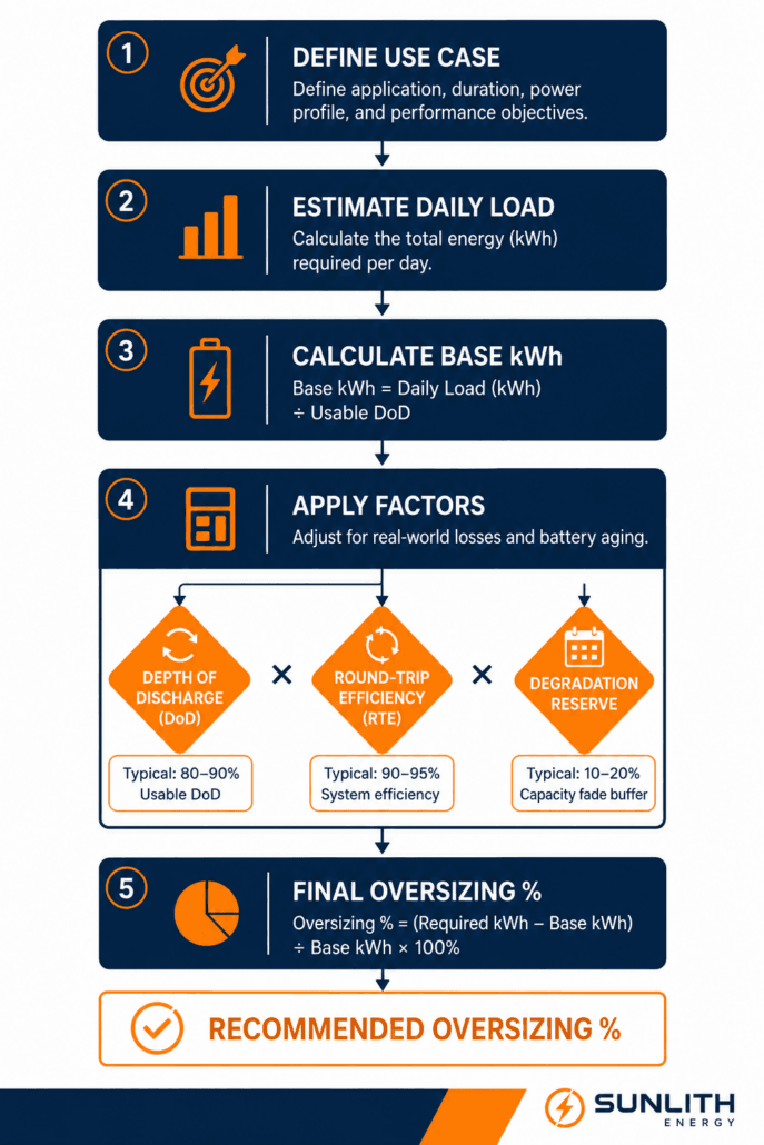
Rather than guessing at an oversizing percentage, use this structured four-step framework to determine whether BESS oversizing is appropriate for your project and, if so, by how much. As a result, you will arrive at a defensible, financially grounded nameplate capacity rather than an arbitrary rule of thumb.
Step 1 — Load Analysis: Gather Real Interval Data
First, collect at least 12–24 months of 15-minute interval load data. Identify peak demand events, average daily consumption, and seasonal variation patterns. This step is non-negotiable: BESS oversizing justified by rough annual consumption estimates rather than interval data almost always produces either over-engineered or under-performing systems.
Step 2 — Base Capacity Calculation
Next, apply the standard sizing formula — daily load × autonomy days ÷ (DoD × RTE) — to establish the minimum required nameplate capacity. This gives you the floor, not the target. However, it also reveals exactly how sensitive the result is to your DoD and RTE assumptions.
Step 3 — Apply Chemistry and Use-Case Correction
Subsequently, determine your oversizing factor based on battery chemistry (LFP vs NMC vs NCA), use case (peak shaving vs backup vs grid services), and EOL capacity requirement. Reference the sizing guide table in Section 6 for starting-point percentages, then adjust based on site-specific factors including climate, cycling frequency, and interconnection limits.
Step 4 — Financial Validation: Model Both Scenarios
Finally, model the oversized vs precisely sized scenarios in a full project NPV and IRR analysis, incorporating ITC capture, degradation trajectory, load growth assumptions, and augmentation cost projections. As a result, you will arrive at the scenario that maximises risk-adjusted return while meeting contracted performance obligations. Choose the strategy with the superior risk-adjusted NPV — not the one that simply installs the most battery.
Conclusion: BESS Oversizing Is a Strategy, Not a Default
BESS oversizing is one of the most powerful tools in a storage developer’s arsenal — but only when applied with precision. When the economics support it, oversizing by 10–25% delivers longer cycle life, a built-in degradation buffer, greater resilience, higher solar self-consumption, and maximised ITC capture. Conversely, when applied without a sound load analysis and financial model, it simply commits capital to cells that will never discharge.
The right approach is always project-specific. Therefore, an LFP C&I peak shaving project with a 10-year capacity guarantee may need 15–20% BESS oversizing to meet EOL targets. A residential grid-tied backup system with low daily DoD requirements may need only 10%. An off-grid microgrid with strict autonomy requirements and no grid fallback may need 25–30%. Furthermore, as battery prices continue to fall, the break-even point between oversizing and augmentation will shift — making it essential to rerun the financial model on each new project rather than applying a fixed rule.
At Sunlith Energy, every BESS project we design goes through a rigorous sizing and degradation modelling process — using real interval load data, validated chemistry models, and financial sensitivity analysis. To learn more about how we approach BESS design, explore our BESS specifications guide, our Battery SoH estimation guide, or review the NLR Grid-Scale Battery Storage Technology Basics for independent technical context. The goal is never the largest battery — it is the right battery, sized correctly for your project’s lifetime.
| Ready to size your BESS correctly? Contact the Sunlith Energy team for a technical consultation. We combine 14+ years of LiFePO4 expertise with advanced degradation modelling to design storage systems that perform at end of life, not just on commissioning day. |