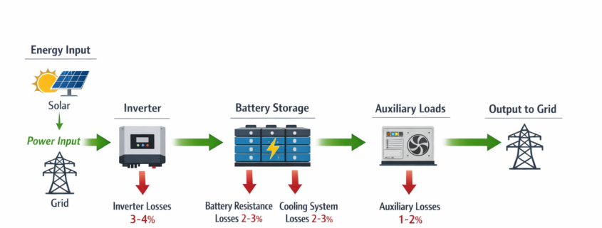
Energy storage losses in BESS systems occur when a portion of electrical energy is lost during charging, storage, and discharge due to battery resistance, inverter conversion, cooling systems, and auxiliary equipment.
Introduction
Energy Storage Losses: Battery Energy Storage Systems (BESS) are designed to store electricity and release it when needed, improving grid reliability and supporting renewable energy integration. However, no energy storage system operates with perfect efficiency.
During charging, storage, and discharge, a portion of energy is lost due to electrical, thermal, and operational processes. These energy storage losses directly affect the round trip efficiency of battery systems.
Understanding where these losses occur is essential for optimizing system performance and improving the economics of energy storage projects.
Energy storage losses refer to the difference between the amount of energy used to charge a battery and the amount of energy that can be recovered when the battery discharges.
These losses are commonly measured using round trip efficiency (RTE).
Example:
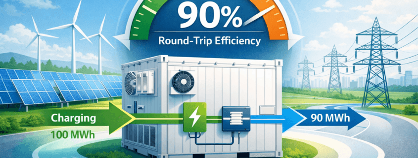
Energy input: 100 MWh Energy output: 90 MWh
Round trip efficiency = 90%
The remaining 10% represents energy lost within the system.
A detailed explanation of how efficiency is calculated can be found in Sunlith’s article on BESS round trip efficiency.
Major Sources of Energy Loss in Battery Storage Systems
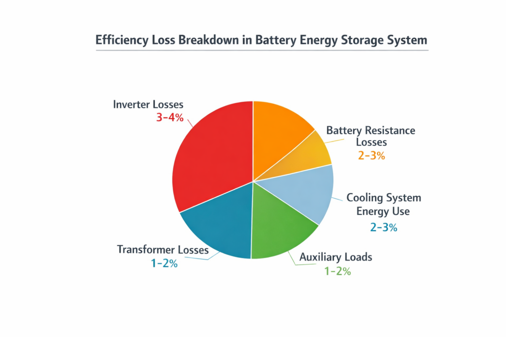
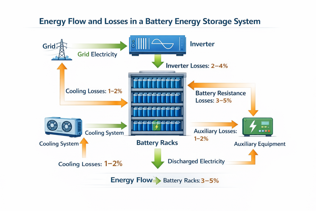
Energy losses in battery storage systems typically occur in several key areas.
Battery Internal Resistance Losses
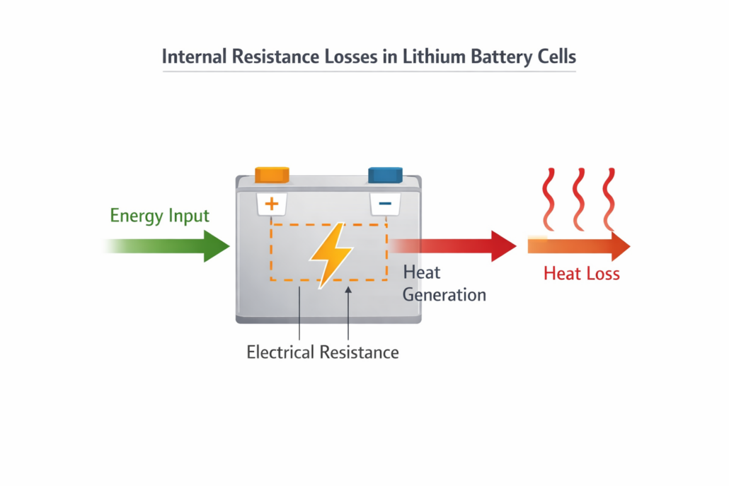
#image_title
Every battery cell has internal electrical resistance.
When electricity flows through the battery during charging and discharging, some of the energy is converted into heat.
This phenomenon is known as resistive loss.
Factors that influence this loss include:
battery chemistry
temperature
current flow
battery age
Modern lithium-ion batteries minimize internal resistance, but these losses cannot be completely eliminated.
Power Conversion Losses
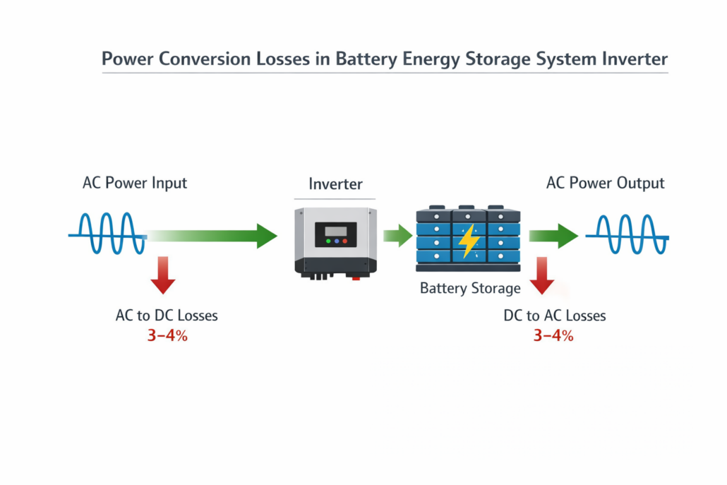
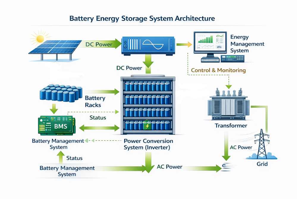
One of the largest sources of energy loss occurs during the conversion between AC and DC electricity.
AC electricity from the grid into DC electricity for charging
DC electricity from batteries back into AC power for the grid
Typical inverter efficiency is between 96% and 98%, meaning some energy is lost during each conversion cycle.
Because electricity passes through the inverter multiple times, these losses accumulate.
Thermal Management Losses
Battery systems generate heat during operation. If not properly controlled, excessive heat can reduce battery performance and shorten system lifespan.
To maintain optimal operating conditions, BESS installations use thermal management systems such as:
HVAC cooling systems
liquid cooling systems
air cooling systems
These systems consume energy continuously, contributing to overall efficiency losses.
Efficient thermal design is critical for minimizing these losses in large-scale battery installations.
Auxiliary System Consumption
Battery energy storage systems contain several supporting components that operate continuously.
These auxiliary systems include:
battery management systems (BMS)
monitoring equipment
fire detection and suppression systems
communication hardware
safety controls
Although each component uses a small amount of energy, together they contribute to system losses over time.
Idle and Standby Losses
Energy storage systems do not always operate continuously. During idle periods, some components still consume power.
These standby losses may occur when:
the system is waiting for dispatch signals
monitoring systems remain active
cooling systems operate intermittently
Reducing standby power consumption can significantly improve overall system efficiency.
Transmission and Distribution Losses
In grid-scale installations, electricity may travel through transformers and power distribution equipment before reaching the grid.
Each additional electrical component introduces small energy losses.
Although these losses are typically minor, they become significant in very large utility-scale installations.
Typical Efficiency of Modern BESS Systems
Modern lithium-ion battery storage systems have improved significantly over the past decade.
Typical round trip efficiency ranges include:
Battery Technology
Round Trip Efficiency
Lithium-ion
90–95%
Lithium Iron Phosphate
90–94%
Lead-acid
70–85%
Flow batteries
65–80%
These values reflect the combined impact of all energy losses within the system.
How to Reduce Energy Storage Losses
Energy storage developers use several strategies to improve efficiency.
High-Efficiency Power Conversion Systems
Advanced inverter technologies reduce power conversion losses by using improved semiconductor switching devices.
New technologies such as silicon carbide power electronics offer higher efficiency and lower heat generation.
Advanced Thermal Management
Optimizing cooling systems helps reduce energy consumption while maintaining battery performance.
Liquid cooling systems can often achieve better efficiency than traditional air cooling solutions.
Intelligent Energy Management Systems
Energy management software optimizes battery charging and discharging schedules.
By operating batteries within optimal conditions, these systems minimize energy losses and extend battery life.
Optimized System Architecture
Choosing the correct system architecture, such as AC-coupled or DC-coupled configurations, can also influence efficiency.
Reducing unnecessary energy conversions can significantly improve overall system performance.
Why Minimizing Energy Loss Matters
Reducing energy losses improves the overall economics of energy storage projects.
Higher efficiency leads to:
more usable stored energy
lower operational costs
higher project profitability
improved renewable energy utilization
Even small improvements in efficiency can produce large financial benefits for large-scale energy storage installations.
The Future of High-Efficiency Energy Storage
Battery technology continues to evolve rapidly. Emerging innovations are expected to further reduce energy losses in storage systems.
These innovations include:
next-generation battery chemistries
solid-state batteries
advanced power electronics
AI-driven energy management systems
As these technologies mature, battery storage systems will become even more efficient and reliable.
Conclusion
Energy storage losses are an unavoidable part of battery energy storage systems. However, understanding where these losses occur allows engineers and developers to optimize system design and improve overall efficiency.
By minimizing losses from batteries, power electronics, thermal management, and auxiliary systems, modern BESS installations can achieve high levels of performance and reliability.
As energy storage becomes increasingly important for renewable power systems, improving efficiency will remain a key focus for the industry.
Understanding AC vs DC round trip efficiency is essential when evaluating the performance of modern Battery Energy Storage Systems (BESS). Efficiency determines how much stored electricity can actually be delivered back to the grid or facility after charging.
Energy storage systems are increasingly used to support renewable energy integration, improve grid stability, and reduce electricity costs. However, every battery storage system experiences some level of energy loss during charging and discharging cycles.
The efficiency of a battery system is usually measured using round trip efficiency (RTE), which represents the percentage of energy recovered compared to the energy used to charge the battery.
Round trip efficiency measures the ratio of usable energy output to energy input during a full charge and discharge cycle.
The formula is:
Round Trip Efficiency = Energy Output ÷ Energy Input × 100
Example:
Energy charged into battery: 100 kWh Energy discharged: 90 kWh
Round trip efficiency = 90%
This metric is widely used in energy storage project evaluation. If you want to understand how this value is calculated in detail, see our guide on BESS Round Trip Efficiency calculation.
According to research from the National Renewable Energy Laboratory, modern lithium battery systems typically achieve round trip efficiencies between 85% and 95% depending on system design.
What is DC Round Trip Efficiency?
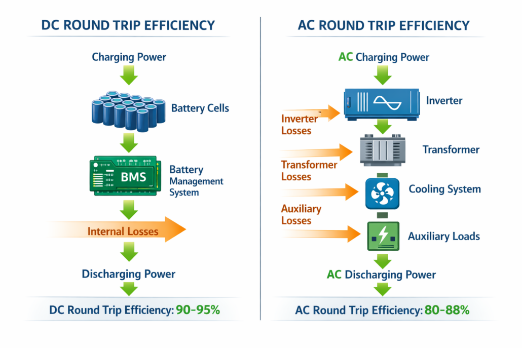
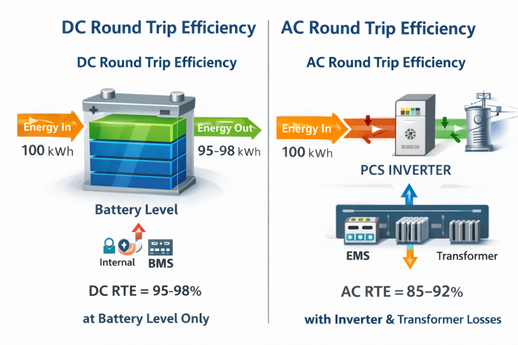
DC round trip efficiency measures the energy efficiency of the battery itself, excluding most external components such as inverters and transformers.
This measurement focuses mainly on the electrochemical performance of the battery cells.
DC efficiency accounts for losses related to:
internal battery resistance
chemical reactions within cells
battery management system operations
Because it excludes several system components, DC round trip efficiency is typically higher than AC efficiency.
Typical DC Efficiency Values
Battery Type
DC Round Trip Efficiency
Lithium-ion
95–98%
Lithium Iron Phosphate (LFP)
94–97%
Lead-acid
80–90%
These values represent the intrinsic performance of the battery technology itself.
What is AC Round Trip Efficiency?
AC round trip efficiency measures the efficiency of the entire energy storage system, including all electrical conversion equipment.
Energy flow in an AC measurement typically follows this path:
Grid → Inverter → Battery → Inverter → Grid
Since electricity passes through several components, additional energy losses occur.
AC efficiency includes losses from:
Power Conversion System (PCS)
Transformers
Thermal management systems
Auxiliary equipment
As a result, AC round trip efficiency is usually lower than DC efficiency.
Typical AC efficiency values for modern lithium battery storage systems range from 85% to 92%.
Key Differences Between AC vs DC Round Trip Efficiency
DC vs AC energy efficiency comparison
Understanding AC vs DC round trip efficiency is important when comparing energy storage solutions.
Metric
DC Efficiency
AC Efficiency
Measurement scope
Battery cells only
Entire system
Includes inverter losses
No
Yes
Includes cooling loads
No
Yes
Typical efficiency range
94–98%
85–92%
Used for project evaluation
Limited
Yes
📉 BESS Round-Trip Efficiency (RTE) Loss Calculator
Enter your baseline generation power to calculate conversion losses.
🔋 DC-COUPLED (85% RTE)
85.0 kW
15.0 kW Lost
🔌 AC-COUPLED (80% RTE)
80.0 kW
20.0 kW Lost
*Estimates assume standard three-stage conversion configurations for AC topologies vs single-stage buck/boost paths for DC.
While DC efficiency measures battery chemistry performance, AC efficiency reflects real-world system performance.
Where Energy Losses Occur in Battery Storage Systems
Inverters convert electricity between alternating current (AC) and direct current (DC).
Even high-performance inverters operate at 96–98% efficiency, meaning small energy losses occur during every conversion.
These losses accumulate because electricity passes through the inverter multiple times during charging and discharging.
The International Energy Agency highlights that inverter losses are one of the most important factors affecting overall energy storage efficiency.
Thermal Management Losses
Battery systems generate heat during operation. Without effective cooling, excessive temperatures can damage battery cells and reduce performance.
Thermal management systems such as:
air cooling systems
liquid cooling systems
HVAC units
consume energy continuously, which reduces overall system efficiency.
Efficient cooling design is therefore critical for large-scale battery storage installations.
Auxiliary System Consumption
BESS installations include several supporting components that operate continuously.
Examples include:
battery management systems
monitoring equipment
fire suppression systems
communication hardware
Although each device consumes relatively little energy, their combined power usage contributes to overall energy losses.
AC vs DC Round Trip Efficiency in Solar + Storage Systems
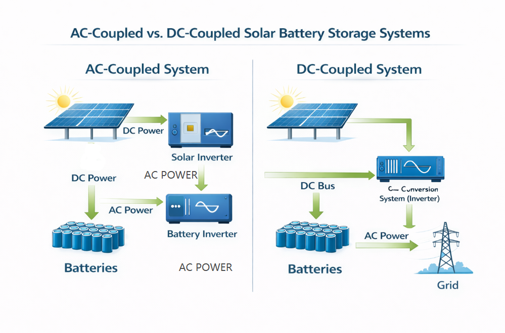
#image_title
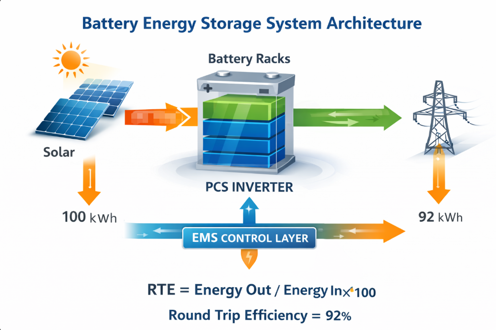
Solar energy systems combined with battery storage can be designed using AC-coupled or DC-coupled configurations.
DC-coupled systems usually achieve higher efficiency because solar energy can be stored directly in the battery without multiple conversions.
AC-coupled systems provide greater flexibility but may introduce additional energy losses due to extra inverter stages.
Choosing the appropriate architecture depends on system design goals, project scale, and grid integration requirements.
Why AC Round Trip Efficiency Matters for Energy Projects
While DC efficiency provides insight into battery chemistry performance, AC round trip efficiency is the most important metric for real-world projects.
Energy developers evaluate systems based on the amount of usable electricity delivered to the grid.
Higher AC efficiency leads to:
increased usable stored energy
improved project profitability
lower operating costs
better renewable energy utilization
This is particularly important for applications such as:
peak shaving
renewable energy integration
grid stabilization
Strategies to Improve Battery Storage Efficiency
Developers can improve system efficiency through several engineering approaches.
High-Efficiency Power Conversion Systems
Modern inverters using advanced semiconductor technologies such as silicon carbide (SiC) can significantly reduce conversion losses.
Optimized Thermal Management
Efficient cooling technologies reduce auxiliary power consumption while maintaining optimal battery temperatures.
Intelligent Energy Management Systems
Advanced energy management software optimizes charging and discharging cycles to maximize system efficiency.
Conclusion
Understanding AC vs DC round trip efficiency in battery energy storage systems is essential for evaluating system performance and project economics.
DC efficiency measures the intrinsic performance of battery cells, while AC efficiency reflects the efficiency of the complete energy storage system.
For most real-world applications, AC round trip efficiency provides the most accurate indicator of system performance.
As battery technology and power electronics continue to evolve, energy storage systems will achieve even higher levels of efficiency and reliability.
FAQ About AC vs DC Round Trip Efficiency
What is AC round trip efficiency?
AC round trip efficiency measures the percentage of energy recovered from a battery after accounting for all system losses including inverters, cooling systems, and auxiliary equipment.
What is DC round trip efficiency?
DC round trip efficiency measures the efficiency of the battery cells themselves, excluding most system-level components.
Why is AC efficiency lower than DC efficiency?
AC efficiency includes losses from power conversion systems, cooling equipment, and other components that are not included in DC efficiency calculations.
What is the typical round trip efficiency of lithium battery storage systems?
Most lithium-ion battery energy storage systems achieve round trip efficiencies between 85% and 95% depending on system design.
BESS Round Trip Efficiency(RTE) measures how much energy a battery returns compared to the energy used to charge it. In other words, it shows how efficiently the storage system operates.
This is why Round Trip Efficiency (RTE) is one of the most important performance metrics in energy storage projects.
A higher BESS RTE means lower energy losses and better system economics. Therefore, utilities, renewable developers, and commercial energy users carefully evaluate this metric when selecting battery storage solutions.
To understand battery storage performance, engineers calculate BESS round trip efficiency using a simple formula.
BESS Round Trip Efficiency Formula
BESS Round Trip Efficiency(RTE) measures how much energy a battery energy storage system returns after charging.
Formula
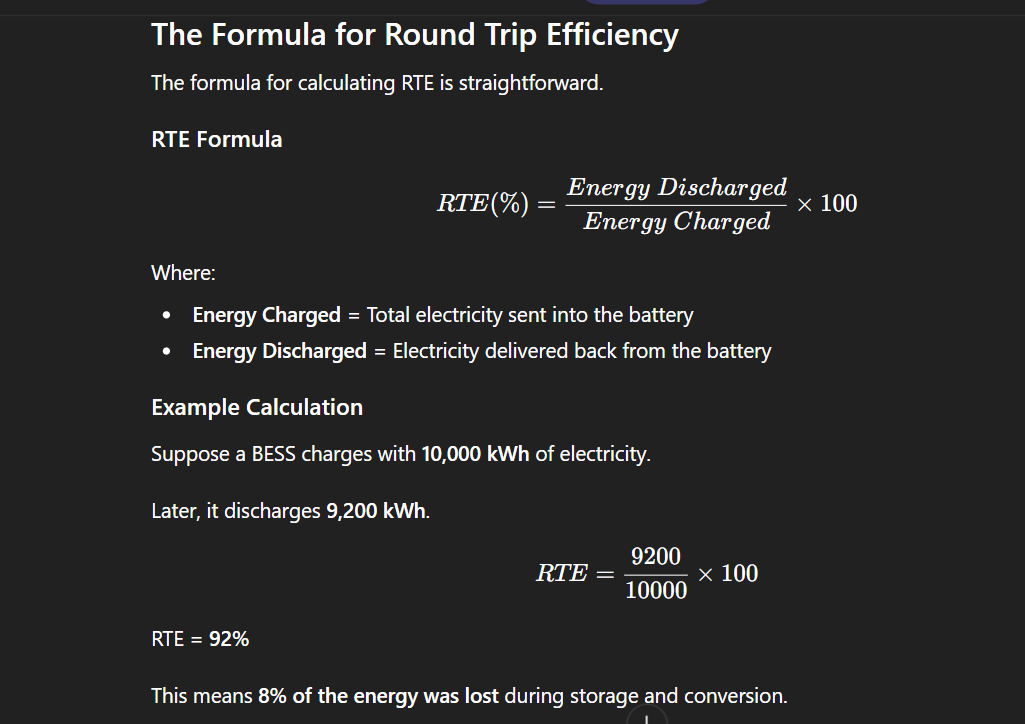
RTE (%) = Energy Discharged ÷ Energy Charged × 100
Example
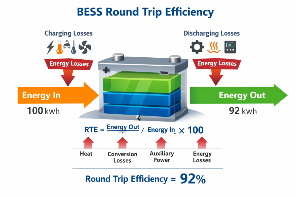
Energy Charged = 100 kWh Energy Discharged = 92 kWh
BESS Round Trip Efficiency = 92%
Most lithium battery energy storage systems achieve 88–94% AC round trip efficiency.
What Is BESS Round Trip Efficiency (RTE)?
BESS RTE represents the percentage of energy that can be recovered from a battery after a full charge and discharge cycle.
During energy storage, electricity flows through several system components. Each component introduces small losses. As a result, the output energy is always slightly lower than the input energy.
These losses typically occur in:
battery cells
power conversion systems
thermal management systems
auxiliary equipment
Therefore, BESS RTE reflects the combined efficiency of the entire storage system.
Why BESS Round Trip Efficiency (RTE) Matters
Understanding BESS round trip efficiency is important because it directly affects project performance and profitability.
First, higher efficiency means more usable electricity. This improves overall system performance.
Second, improved BESS RTE reduces operational energy losses. As a result, storage projects can generate higher revenue from energy trading and peak-shaving services.
In addition, efficient battery systems support grid stability. They store renewable energy during periods of excess generation and release it during high demand.
Modern energy storage solutions such as those offered by SunLith Energy are designed to maximize efficiency through advanced battery design and system integration.
How to Calculate BESS Round Trip Efficiency
BESS Round Trip Efficiency Formula
The calculation of BESS RTE is straightforward. However, engineers must carefully measure the energy entering and leaving the system.
BESS Round Trip Efficiency Formula
RTE (%) = Energy Discharged ÷ Energy Charged × 100
Where:
Energy Charged = total electricity stored in the battery
Energy Discharged = electricity delivered from the battery
This formula helps determine the overall efficiency of the storage cycle.
Step 1: Measure Charging Energy
First, record the total electricity supplied to the battery system during charging.
This measurement usually occurs at the grid connection point or the inverter input.
Example:
Energy charged = 5 MWh
Step 2: Measure Discharge Energy
Next, measure the electricity delivered by the battery during discharge.
Example:
Energy discharged = 4.6 MWh
Step 3: Calculate BESS Round Trip Efficiency
Using the formula:
RTE = 4.6 ÷ 5 × 100
Result:
BESS Round Trip Efficiency = 92%
Therefore, the system lost 8% of energy during the storage cycle.
🔋 Interactive BESS RTE Calculator
Enter your system’s metered energy values to determine true round-trip performance.
Calculated Round-Trip Efficiency
92.0%
0.4 MWh Lost to Conversion & Heat
📊 Assessment: **Excellent performance** typical of premium Lithium Iron Phosphate (LFP) utility arrays.
AC vs DC BESS Round Trip Efficiency
#image_title
Engineers often calculate BESS round trip efficiency using two different system boundaries.
These measurements are known as DC efficiency and AC efficiency.
Energy efficiency has a direct impact on battery storage revenue.
For example, consider a 100 MWh battery system operating with 90% round trip efficiency.
Each cycle loses 10 MWh of energy.
If the battery cycles 300 times per year, the total annual energy loss becomes:
3,000 MWh
Therefore, improving BESS RTE can significantly increase project profitability.
Summary
What is BESS Round Trip Efficiency?
BESS RTE measures how much stored electricity a battery returns after charging.
Formula
RTE (%) = Energy Discharged ÷ Energy Charged × 100
Example
If a battery stores 100 kWh and delivers 92 kWh:
BESS Round Trip Efficiency = 92%
Typical Efficiency
Lithium battery systems: 88–94% AC efficiency
Flow batteries: 65–80%
Lead-acid batteries: 70–85%
Higher BESS RTE means lower energy losses and better storage economics.
FAQ About BESS Round Trip Efficiency (RTE)
What is a good BESS Round Trip Efficiency (RTE)?
A good BESS RTE for lithium-ion battery storage systems is typically 88% to 94% AC efficiency. At the battery level, DC efficiency can reach 95–98% depending on battery chemistry and inverter performance.
Does battery aging affect BESS round trip efficiency?
Yes. As batteries age, internal resistance increases. This can slightly reduce BESS RTE over time.
Why do lithium batteries have higher efficiency?
Lithium batteries have lower internal resistance and more efficient electrochemical reactions compared with older battery technologies.
Introduction: Why Iron-Air Batteries Are Gaining Attention
Iron-Air Battery: Renewable energy is growing fast. Solar and wind now supply a large share of electricity in many regions. However, both sources depend on weather conditions.
As a result, grids need energy storage systems that can deliver power even when the sun is not shining and the wind is not blowing.
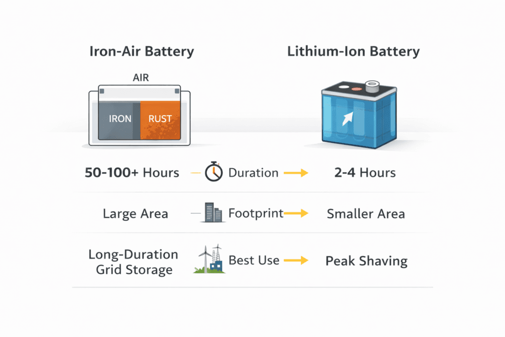
Lithium-ion batteries help solve short-term gaps. Typically, they provide two to four hours of storage. Yet this is not enough during multi-day weather events.
This makes long-duration energy storage a major focus for grid operators, with iron-air technology standing out as a frontrunner.
Summary
What is an iron-air battery? An iron-air battery is a long-duration energy storage system that produces electricity through a reversible reaction between iron and oxygen.
How does it work? During discharge, iron reacts with oxygen and forms rust. During charging, electricity converts the rust back into iron.
How long does it last? Commercial systems are designed to deliver 50 to 100+ hours of power.
Where is it used? Iron-air batteries are used in utility-scale grid storage and renewable integration projects.
How is it different from lithium-ion? Iron-air provides much longer duration at lower material cost, but it requires more space and has lower energy density.
What Is an Iron-Air Battery?
An iron-air battery is a type of metal-air battery. It uses iron as one electrode and oxygen from the surrounding air as the other reactant.
Unlike lithium-ion cells, iron-air systems feature an open design to draw oxygen directly from the atmosphere. Instead, they pull oxygen directly from the atmosphere. This approach reduces material costs and simplifies chemistry.
The technology has gained attention through companies such as Form Energy, which is developing commercial 100-hour battery systems for grid use.
Because iron is cheap and widely available, this chemistry offers strong cost potential for long-duration storage.
How Does an Iron-Air Battery Work?
Iron-air batteries rely on a reversible rusting process. Although the concept sounds simple, the engineering behind it is sophisticated.
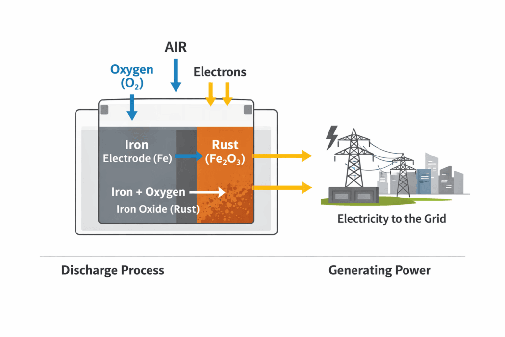
Discharge Phase: Producing Electricity
During discharge:
Iron reacts with oxygen
Iron oxide (rust) forms
Electrons move through an external circuit
Electricity flows to the grid
In simple terms, the battery “rusts” to generate power.
Charge Phase: Storing Energy
When the battery charges:
External electricity is applied
Iron oxide converts back into iron
Oxygen is released
Consequently, the system resets and becomes ready for the next cycle.
Even though the reaction is straightforward, system control requires airflow management, moisture balance, and electrolyte stability. Therefore, large-scale engineering plays a critical role in performance.
Why Iron-Air Batteries Are Important for the Grid
As renewable penetration rises above 50%, short-duration storage alone cannot stabilize the grid. Multi-day weather patterns can reduce both solar and wind output.
For example, extended cloudy and low-wind periods create serious reliability challenges. Under these conditions, four-hour batteries are insufficient.
Iron-air systems address this gap.
Multi-Day Energy Storage
Most iron-air designs target 50 to 100 hours of discharge. This duration supports:
Renewable smoothing
Coal plant retirement
Reduced gas peaker dependence
Grid resilience during extreme weather
Because of this capability, utilities are actively evaluating long-duration solutions.
Lower Material Cost
Iron is one of the most abundant elements on Earth. In contrast, lithium and nickel markets can experience volatility.
As a result, iron-air batteries reduce exposure to critical mineral supply risks. Over time, this could lower the levelized cost of storage for long-duration projects.
Iron-air, on the other hand, targets bulk energy shifting over extended periods.
Where Are Iron-Air Batteries Installed?
Manufacturers design iron-air systems specifically for utility-scale deployment, typically installing them near:
Substations
Renewable generation sites
Coal plant retirement locations
Dedicated storage facilities
Because energy density is lower, these systems require more land. However, utilities often have sufficient space for such installations.
Residential or electric vehicle applications are not suitable for this chemistry.
Advantages of Iron-Air Batteries
Iron-air technology offers a distinctive set of advantages that make it compelling specifically for utility-scale, long-duration grid storage. These benefits are not incremental improvements over existing storage — they represent a fundamentally different cost and duration profile that no other commercially available battery chemistry currently matches.
1. Ultra-Low Raw Material Cost
Iron is one of the most abundant elements on Earth, making up approximately 5% of the planet’s crust. Unlike lithium, cobalt, or nickel — whose prices can spike due to geopolitical concentration — iron is produced in over 50 countries with stable, diversified supply chains. According to the IEA battery storage report, reducing critical mineral dependency is one of the most important steps toward a resilient, low-cost grid storage industry. Iron-air batteries achieve this by design.
2. 100-Hour Discharge Duration
Most iron-air systems, including the commercial Form Energy iron-air battery system, are designed for up to 100 continuous hours of discharge. This makes them uniquely suited to multi-day renewable energy gaps — extended periods of low solar irradiance and low wind — that short-duration lithium-ion batteries cannot economically address. As renewable penetration crosses 50–70% in major grids, multi-day storage transitions from a niche capability to a grid reliability requirement.
3. No Critical Mineral Supply Chain Risk
Iron-air batteries contain no lithium, cobalt, nickel, or manganese. This eliminates exposure to the supply concentration risks that affect lithium-ion: approximately 60% of cobalt production comes from the Democratic Republic of Congo, and over 70% of lithium refining occurs in China. Iron-air batteries are therefore better positioned for long-duration energy storage (LDES) deployment in markets prioritizing domestic energy security.
4. Non-Flammable Cell Chemistry
The electrochemical reactions in iron-air batteries use iron metal, oxygen from air, and an aqueous potassium hydroxide (KOH) electrolyte. None of these components is inherently flammable. This contrasts with lithium-ion cells, which use organic electrolytes that can enter thermal runaway under fault conditions. As grid storage projects scale to GWh capacities, cell-level fire risk becomes a critical design factor — and iron-air’s chemistry offers a meaningful advantage. For relevant BESS certifications and safety standards applicable to large-scale installations, NFPA 855 and IEC 62933 still apply to the system level regardless of chemistry.
5. Highly Scalable Capacity
Iron-air systems use modular cell stacks. Adding capacity means adding modules — there is no fundamental chemistry barrier to scaling from MWh to GWh. This modularity aligns well with phased utility procurement strategies, where developers may initially deploy 100 MWh and expand incrementally as demand grows.
6. Compelling Levelized Cost of Storage (LCOS)
At a projected system cost of approximately $20/kWh — compared with $250–400/kWh for lithium-ion grid storage systems — iron-air batteries target a levelised cost of storage (LCOS) of $20–40/MWh for 100-hour discharge applications, according to NREL grid storage cost benchmarks. This figure makes iron-air competitive with new-build gas peaker plants even before accounting for carbon pricing or clean energy incentive structures.
✔ Advantages
✘ Limitations
✔ Low raw material cost — iron is one of Earth’s most abundant and inexpensive metals
✘ Lower energy density than lithium-ion — requires significantly more land per MWh
✔ 100-hour discharge capability fills multi-day renewable energy gaps that lithium-ion cannot address
✘ Round-trip efficiency of 50–60% is lower than lithium-ion (85–95%), increasing energy input cost per cycle
✔ No lithium, cobalt, or nickel — eliminates critical mineral supply chain risk and price volatility
✘ Commercial scale is still early-stage — limited bankability track record for project finance
✔ Aqueous KOH electrolyte is non-flammable and low-toxicity — reducing cell-level fire risk
✘ Slow charge and discharge response makes it unsuitable for frequency regulation or fast-response grid services
✔ Highly scalable — system capacity can reach GWh range using modular iron-air cell stacks
✘ Air electrode durability and iron anode corrosion management are active engineering challenges
✔ Projected system cost of ~$20/kWh unlocks an LCOS of $20–40/MWh for long-duration grid storage
✘ Interconnection queue delays in US ISOs can add 3–5 years to project timelines
💡 Key insight: The advantages of iron-air batteries are most powerful when evaluated against the correct baseline: not short-duration lithium-ion, but the cost of multi-day grid firming using gas peakers or pumped hydro. Against those benchmarks, iron-air’s cost and duration profile is highly competitive.
Limitations and Engineering Challenges
Iron-air batteries carry real constraints that developers, utilities, and investors must understand clearly. However, understanding these limitations in full context — including why they exist and how they compare with alternative technologies — is essential for accurate project evaluation.
1. Lower Energy Density Requires More Land
Iron-air batteries have significantly lower volumetric energy density than lithium-ion. A utility-scale iron-air system may require 5–10× more land per MWh than an equivalent LFP lithium-ion installation. For projects near urban centers or in land-constrained regions, this is a genuine site selection constraint. However, utility-scale projects targeting multi-day storage are typically sited on large parcels near substations or generation assets, where land availability is less limiting. For compact commercial and industrial projects, battery energy storage systems (BESS) using LFP or NMC chemistries remain the correct choice.
2. Round-Trip Efficiency: The 50–60% Trade-Off
Round-trip efficiency (RTE) measures energy recovered per unit of energy stored. Iron-air systems currently achieve 50–60% RTE, compared with 85–95% for lithium-ion. This means that for every 100 kWh charged, only 50–60 kWh is recovered on discharge. The following comparison shows why this trade-off is accepted for long-duration applications:
Metric
Iron-Air
LFP Lithium-Ion
Vanadium Flow
Round-Trip Efficiency
50–60%
85–95%
65–75%
Max Discharge Duration
100+ hours
4–8 hours
8–12 hours
System Cost ($/kWh)
~$20
$250–400
$300–500
LCOS ($/MWh, long-duration)
$20–40
Not viable >8 hr
$80–120
Best Application
Multi-day grid firming
Peak shaving / C&I
Daily cycling / medium duration
As the table shows, iron-air’s lower RTE is offset by its dramatically lower cost per kWh and its ability to discharge for 100+ hours — a duration at which lithium-ion is not economically viable regardless of efficiency. For more on how these specifications are evaluated in project procurement, see BESS specifications.
3. Early Commercialization Stage
As of 2026, iron-air battery technology is at the early commercial stage. Form Energy’s Weirton, West Virginia facility is the first high-volume manufacturing site globally. While over 75 GWh of iron-air capacity is under commercial agreement, actual installed operating experience remains limited compared with lithium-ion’s decade-plus of utility-scale deployments. This limits bankability — project finance lenders and insurance underwriters require operating data that is still accumulating. Consequently, early iron-air projects may carry higher financing costs than equivalent lithium-ion installations.
4. Slow Response Speed
Iron-air batteries are designed for bulk energy shifting over long periods, not rapid power delivery. Their response time — the speed at which they can ramp from standby to full output — is slower than lithium-ion. This makes them unsuitable for frequency regulation, spinning reserve, or other ancillary grid services that require sub-second response. A grid-scale BESS combining lithium-ion for fast response with iron-air for long-duration firming represents the emerging standard for high-renewable-penetration grids.
5. Air Electrode and Corrosion Engineering
The bifunctional air electrode — which must perform both the Oxygen Reduction Reaction (ORR) during discharge and the Oxygen Evolution Reaction (OER) during charging — is the most technically demanding component of an iron-air system. Designing an electrode that can sustain both reactions across thousands of cycles without degradation requires advanced catalyst and materials engineering. In parallel, iron anode corrosion management — specifically preventing parasitic side reactions such as hydrogen evolution — is an active area of development that directly impacts system cycle life.
6. Interconnection and Permitting Timelines
In the United States, the interconnection queue managed by ISOs such as CAISO, MISO, PJM, and ERCOT currently imposes multi-year delays on large storage projects. According to the DOE long-duration storage program, queue reform is an active policy priority — but as of 2026, developers should budget 3–5 years from interconnection application to energization for large-scale projects. This timeline constraint applies to all grid storage technologies, not just iron-air, but it is particularly relevant for a technology still accumulating its first commercial operating record.
⚖️ Context: None of the limitations above are disqualifying for iron-air’s target application: multi-day, utility-scale grid firming. They are trade-offs that make iron-air unsuitable for short-duration, fast-response, or space-constrained applications — precisely the segments where lithium-ion excels. The two technologies are complementary, not competitive.
The Future of Long-Duration Energy Storage
Energy storage markets are evolving rapidly. As renewable penetration increases, grid planners must diversify storage solutions.