
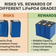
The Hidden Dangers of Low-Grade LiFePO4 Cells: Don’t Get Scammed!
The growing popularity of LiFePO4 (Lithium Iron Phosphate) batteries in solar energy storage, RVs, and off-grid setups has brought a flood of suppliers into the market. It’s tempting, especially for DIYers and budget-conscious buyers, to grab the cheapest deal. But beware — that bargain pack of cells labeled “Grade A” at suspiciously low prices might actually be low-grade or even rejected cells. The short-term savings could cost you big in the long run. how to protect from Battery Scam?
The Trap: Why Cheap Batteries Can Cost You More
There’s a reason reputable suppliers and certified manufacturers charge more for Grade A LiFePO4 cells. High-quality cells are rigorously tested for consistency in capacity, internal resistance, cycle life, and safety. Low-grade or Grade C cells often fail these tests — they’re the factory rejects, excess stock, or even refurbished cells passed off as new.
Unscrupulous sellers know that most buyers can’t test cells themselves. They slap a “Grade A” sticker on low-quality cells and move inventory fast. Once the battery pack fails or causes problems, it’s too late.
Performance Issues: The Hidden Cost of Low-Grade Cells
1. Unexpected Capacity Drops:
Low-grade cells often have inconsistent capacity ratings. You might think you’re getting 100Ah, but in real-world use, you may only get 70–80% of the advertised capacity — if that.
2. Inconsistent Power Output:
Cells with mismatched internal resistance or degraded chemistry can’t deliver stable power. You’ll notice fluctuations, poor performance under load, or even sudden shutoffs — not ideal if you rely on your batteries for critical energy needs.
Safety Hazards: A Risk You Shouldn’t Ignore
LiFePO4 batteries are known for their thermal stability — they’re among the safest lithium chemistries out there. But when cells are low-grade, damaged, or have internal defects, safety goes out the window.
Overheating & Swelling: Poor-quality cells are more prone to swelling due to gas buildup. They can overheat during charging or discharging, increasing the risk of thermal runaway.
Shortened Lifespan and Financial Losses
Imagine spending hundreds or thousands of dollars to build or buy a battery bank, only to have cells fail after a few months. Low-grade cells can lose capacity rapidly, dropping below usable levels in a fraction of the cycles you’d get from genuine Grade A cells.
What’s worse, a single bad cell can drag down an entire battery pack — meaning you may have to replace the whole thing. So, that “cheap” deal can turn into double or triple the cost over time.
How to Protect Yourself: Smart Buying Steps
Don’t get scammed — here’s how to safeguard your project and your wallet:
✅ Do Your Due Diligence: Research suppliers thoroughly. Check reviews, forums, and independent test reports.
✅ Verify Supplier Claims: Reputable sellers will share the factory test reports, including capacity, internal resistance, and cycle life data. Don’t hesitate to ask.
✅ Look for Certifications: Ensure the cells meet international safety standards like UN38.3, IEC, or UL certifications.
✅ Inspect on Arrival: Check the physical condition of cells. Look for dents, swelling, corrosion, or mismatched labels.
✅ Run Your Own Tests: If you have the tools, test cells for capacity and internal resistance before building your pack.
✅ Work with Trusted Partners: Sometimes it’s worth paying a local representative or battery expert to vet suppliers and inspect shipments, especially for bulk orders.
Real-World Examples: When Cheap Batteries Go Bad
🔍 Case in Point:
A small off-grid community bought a pallet of “Grade A” LiFePO4 cells from an unknown online supplier. Within six months, over 40% of the cells were swollen and underperforming. When they tried to claim a warranty, the seller disappeared. They ended up paying twice — once for the junk cells, and again for new, certified replacements.
🔍 Another Example:
A DIYer on a popular solar forum shared photos of cells they’d bought at a discount. They discovered old weld marks under the heat shrink — the cells were clearly recycled from old packs. This can pose both performance and safety issues.
Final Thoughts: Spend Smart, Not Cheap
LiFePO4 batteries are a great investment — but only if you buy quality. When it comes to energy storage, you truly get what you pay for. A cheap battery today can become a costly, even dangerous headache tomorrow.
So, be cautious. Ask questions. Demand data. And when in doubt, remember: a trusted supplier might cost more upfront, but they’ll save you thousands in headaches down the road.
Frequently Asked Questions
Q: Are all Chinese LiFePO4 cells low-grade?
A: No! China is the world’s leading manufacturer of high-quality LiFePO4 cells. The key is buying from reputable factories and verified suppliers.
Q: How can I tell if a cell is Grade A or C?
A: Without testing, it’s hard. That’s why factory test reports, supplier transparency, and independent verification matter so much.
Q: Is buying refurbished or used cells ever worth it?
A: For non-critical applications, maybe. But always expect lower performance and a shorter lifespan — and never use them for applications where reliability is crucial.
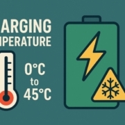
Charging Temperature: The Overlooked Factor in Battery Datasheets
Charging temperature for batteries: When you read a lithium-ion cell datasheet, you’ll usually find a line that states:
“Operating Temperature: -20°C to 60°C.”
Most people take this to mean they can safely charge and discharge the battery anywhere within this range. But here’s the catch — this ‘operating temperature’ often applies only to discharge. In reality, charging temperature limits are much narrower, and charging a battery at too low a temperature can lead to permanent damage, poor performance, or even safety hazards.
Let’s unpack why charging temperature is so critical — and why most cell datasheets don’t clearly show the minimum or maximum charging current at low temperatures.
Why Temperature Matters More for Charging than Discharging
Chemical Reactions Are Temperature Sensitive
Batteries store and release energy through electrochemical reactions. When discharging, the battery’s internal resistance and chemical kinetics can handle lower temperatures reasonably well — albeit with reduced capacity.
But charging is different: at low temperatures, the lithium ions move more slowly and can deposit as metallic lithium on the anode surface instead of intercalating into the graphite layers. This is called lithium plating, and it’s a big problem.
What Is Lithium Plating — and Why Should You Care?
- Safety Risk: Plated lithium can form dendrites that pierce the separator, leading to internal short circuits.
- Capacity Loss: Once lithium plates, it often cannot be recovered, permanently reducing battery capacity.
- Performance Issues: Cells with lithium plating can show increased impedance and reduced power output.
For the full electrochemistry behind why this happens — including how it connects to the slower, ongoing SEI layer growth every LFP cell experiences — see our guide on SEI layer growth and lithium plating in LFP cells.
In short, charging at temperatures below the manufacturer’s recommended minimum can destroy your battery, even if it works fine during discharge.
What Datasheets Usually Show (and What They Don’t)
Typical ‘Working Temperature Range’
Most cell datasheets provide a simple table:
| Parameter | Range |
|---|---|
| Operating Temperature | -20°C to 60°C |
| Storage Temperature | -20°C to 45°C |
Here’s the issue:
- The ‘Operating Temperature’ mostly reflects the discharge range, since discharging is more forgiving.
- The recommended charging temperature range is narrower, often 0°C to 45°C for typical lithium-ion cells.
- Many datasheets don’t list charging current limits at specific low temperatures, which can mislead inexperienced designers or end-users.
Why Charging Current Specs Are Missing
There are a few reasons:
✅ Simplicity: Datasheets are general-purpose and aim to cover a wide range of use cases.
✅ System-Level Responsibility: It’s expected that system integrators will design a Battery Management System (BMS) to enforce proper charging limits.
✅ Testing Constraints: It’s impractical for cell makers to test and specify safe charge currents for every temperature point.
However, high-quality battery packs, EVs, or energy storage systems will always have a BMS with temperature sensors that adjust or cut off charging below safe levels.
How to Interpret the Datasheet Correctly
When you see:
“Operating Temperature: -20°C to 60°C”
Remember:
✅ Discharge: -20°C to 60°C is possible.
✅ Charge: Typically 0°C to 45°C.
Always check if the datasheet has a line like:
“Charging Temperature: 0°C to 45°C”
or a separate graph showing charging current vs. temperature. If it doesn’t, follow standard battery chemistry best practices — and build your BMS to protect the cells.
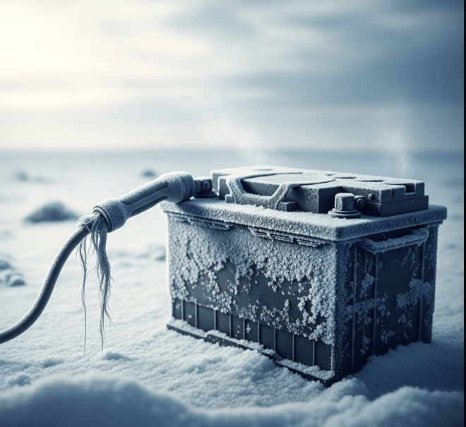
Best Practices for Safe Charging at Low Temperatures
- Use a Good BMS: It must prevent charging below the minimum safe temperature (often 0°C).
- Pre-Heat When Necessary: In cold climates, electric vehicles and energy storage systems use heaters to bring battery packs up to a safe charging temperature.
- Reduce Charge Current: If you must charge slightly below the recommended temperature, reduce current to mitigate lithium plating risk — but always follow manufacturer guidance.
- Monitor and Test: In critical applications, add redundant sensors and logs to track battery health.
Final Thoughts
Charging temperature is often overlooked — until it’s too late. Understanding that the ‘working temperature’ range in a cell datasheet is usually for discharge, not charge, is key to protecting battery performance and lifespan.
Always design your system to account for real-world conditions, and never assume that what works for discharge is safe for charge. After all, a healthy battery is a happy battery — and it all starts with respecting temperature limits.
FAQ: Charging Temperature for Batteries
Q1: Why do manufacturers focus more on discharge temperature?
Discharging is generally safer across wider temperatures, while charging at low temperatures can cause irreversible damage. So the ‘headline’ working range is more about discharge capability.
Q2: Can I charge a lithium-ion battery at -10°C if I use a very low current?
In theory, slower charging reduces plating risk, but it’s still not recommended without manufacturer approval. Always stick to the specified minimum charging temperature.
Q3: How do electric vehicles handle low-temperature charging?
Most EVs have battery heaters that pre-warm the cells to reach a safe temperature range before fast charging begins.
Q4: Does fast charging make the problem worse?
Absolutely. Higher currents increase the risk of lithium plating at lower temperatures. Smart BMS systems reduce charge rates or stop charging altogether if it’s too cold.
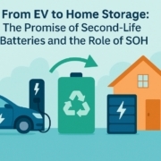
From EV to Home Storage: The Promise of Second-Life Batteries and the Role of SOH
When an electric vehicle (EV) battery no longer delivers the range you expect, is it truly the end of the road? Not necessarily! Welcome to the world of second-life batteries applications, where used EV batteries get a new lease on life powering our homes, businesses, and communities.
In this post, we’ll explore how State of Health (SOH) plays a crucial role in unlocking this sustainable energy solution.
Why Do EV Batteries Reach “End of Life”?
EV batteries typically reach their End of Life (EOL) for vehicle use when their capacity drops to around 70–80% of their original value. While this means they can’t reliably provide the range needed for daily driving, they still hold a significant amount of usable energy.
This is where the concept of second-life batteries comes in — putting these batteries to work in less demanding environments, like stationary battery energy storage systems.
What is a Second-Life Battery?
A second-life battery is a battery that has completed its first life in an electric vehicle and is repurposed for another application. Instead of sending it straight to recycling, these batteries can serve in home energy storage, backup power systems, or grid-scale applications.
Repurposing extends the overall lifespan of the battery materials, reduces waste, and makes clean energy storage more affordable.
The Role of SOH in Second-Life Battery Applications
State of Health (SOH) is the single most important metric for deciding whether a used battery is suitable for a second life. SOH indicates how much usable capacity and performance a battery still has compared to its original specification.
Without accurate SOH data, integrating second-life batteries into energy storage systems would be risky. A battery that looks fine externally might not hold a charge effectively — or worse, it could pose safety risks.
That’s why reputable second-life projects rely on robust SOH testing and screening processes. This ensures that only safe, reliable batteries find a second home.
Second-Life Batteries for Home Energy Storage
One of the most promising uses for second-life batteries is home energy storage. With rooftop solar becoming more common, many homeowners want to store excess solar energy for use at night or during power outages.
Second-life batteries can be an affordable alternative to brand-new battery systems. Here’s why they make sense:
- Lower upfront cost: Second-life batteries are cheaper than new ones.
- Sustainable use of resources: Reusing batteries delays recycling, saving the energy and emissions needed to produce new cells.
- Adequate performance: Home energy storage is less demanding than powering a vehicle — fluctuations in capacity or power delivery are more manageable.
Challenges of Second-Life Batteries
Of course, second-life battery applications are not without challenges.
✅ Variation in SOH: Each battery pack will have a unique SOH, so grading, sorting, and system design are crucial.
✅ Warranty & standards: Consumers want to know their storage system is safe and reliable. Clear standards for SOH testing and certification are still evolving.
✅ Safety: A degraded battery needs to be properly managed by a Battery Management System (BMS) to prevent thermal issues.
How SOH Testing Works
Evaluating SOH involves:
- Capacity tests: Measuring the charge the battery can hold.
- Internal resistance checks: Higher resistance indicates aging.
- Visual & diagnostic inspections: Identifying any physical damage or irregularities.
Advanced diagnostic tools and algorithms make it possible to test large numbers of used EV batteries quickly and reliably, paving the way for scalable second-life applications.
A Step Toward a Circular Battery Economy
By giving EV batteries a second life, we’re taking a big step toward a more circular economy for batteries. Instead of a single-use model, we maximize the value of the raw materials and reduce the demand for new mining.
This approach helps the clean energy transition become even more sustainable and cost-effective for everyone.
Final Thoughts
Second-life battery applications are an exciting example of how we can combine smart technology, sustainability, and practical economics. Next time you think your EV battery is ready for retirement, remember: with the help of accurate SOH measurement, it might just be ready to power your home instead.
FAQs: Second-Life Batteries & SOH
Q1: How long do second-life batteries last?
Second-life batteries can last 5–10 years or more in stationary applications, depending on their SOH and how they’re used.
Q2: Are second-life batteries safe for home use?
Yes — when properly tested for SOH, repurposed batteries are safe for less demanding energy storage applications. Always choose reputable suppliers with strong testing and BMS controls.
Q3: How is SOH measured for second-life batteries?
SOH is measured through capacity testing, resistance checks, and advanced diagnostics to ensure the battery still performs reliably.
A Practical Guide to Battery Cycle Standards: DOD, SOH & EOL
Battery Cycle Standards explain how battery life is measured; however, many datasheets are not clear. As a result, users often misunderstand real-world performance.
In reality, battery life is not a fixed number. Instead, it fluctuates based on usage and environmental conditions. Therefore, Understanding how DOD, SOH, and EOL work together is vital. Therefore, knowing these basics helps you pick the right battery for your needs
💡 Quick Summary: DOD vs SOH vs EOL
For those comparing battery specs, here is the essential relationship:
- DOD (Depth of Discharge): How much energy you take out per cycle (e.g., 80%).
- SOH (State of Health): How much total capacity the battery has left compared to when it was new.
- EOL (End of Life): The “failure point” (usually 80% SOH) where the battery should be replaced.
The Standard: A battery rated for 6,000 cycles at 80% DOD means it can be used 6,000 times before its SOH hits the EOL limit.
What Are Battery Cycle Standards in Batteries?
Battery Cycle Standards measure how many charge and discharge cycles a battery can complete before its capacity drops to 70%–80%.
A battery cycle is formally defined as one full charge and discharge; nevertheless, real-world results depend on several critical factors. Specifically, variables such as temperature, charge rate, and Depth of Discharge (DOD) determine the actual longevity. Consequently, two batteries with identical ratings can perform very differently in different environments
For example:
- Temperature
- Charge rate
- Depth of Discharge
What Is DOD in Battery Cycle Standards?
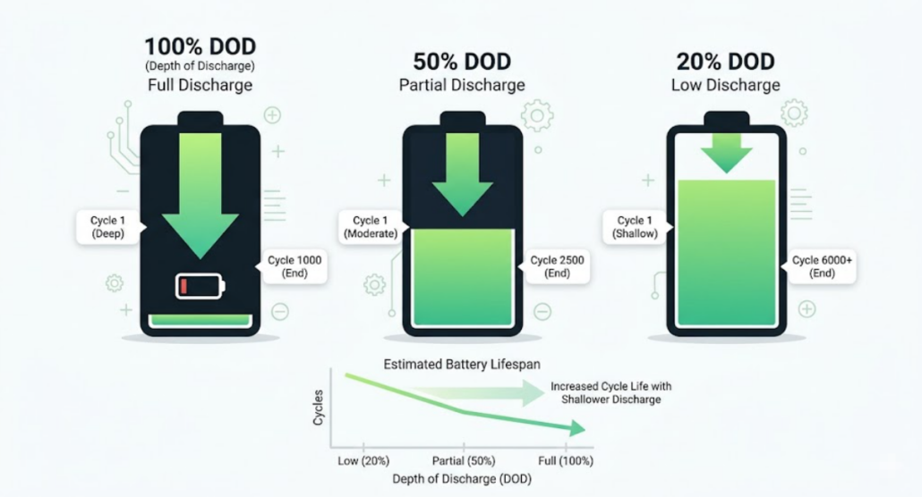
Depth of Discharge (DOD) indicates how much energy is cycled out of the battery; for instance, a 100% DOD means a full discharge, whereas a 50% DOD represents a half discharge.
For example:
- 100% DOD = full discharge
- 50% DOD = half discharge
While a higher DOD significantly increases internal stress and causes battery life to drop, utilizing a lower DOD conversely reduces wear on the cells and extends their longevity.
Example: If your battery is 100Ah and you use 80Ah before recharging, that’s 80% DOD.
What Is SOH in Battery Cycle Standards?
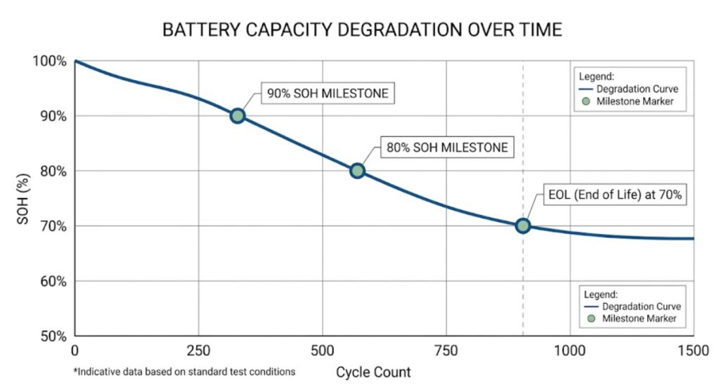
State of Health (SOH) shows remaining battery capacity.
For example:
- 100% SOH = new battery
- 80% SOH = reduced capacity
Over time, the SOH naturally decreases as the internal chemistry of the cells degrades. In addition to tracking wear, SOH serves as a vital indicator for warranty claims, since most manufacturers guarantee a specific capacity percentage over a set number of years.
When SOH drops to 80% or 70%, that’s usually considered End of Life (EOL).
What Is EOL in Battery Cycle Standards?
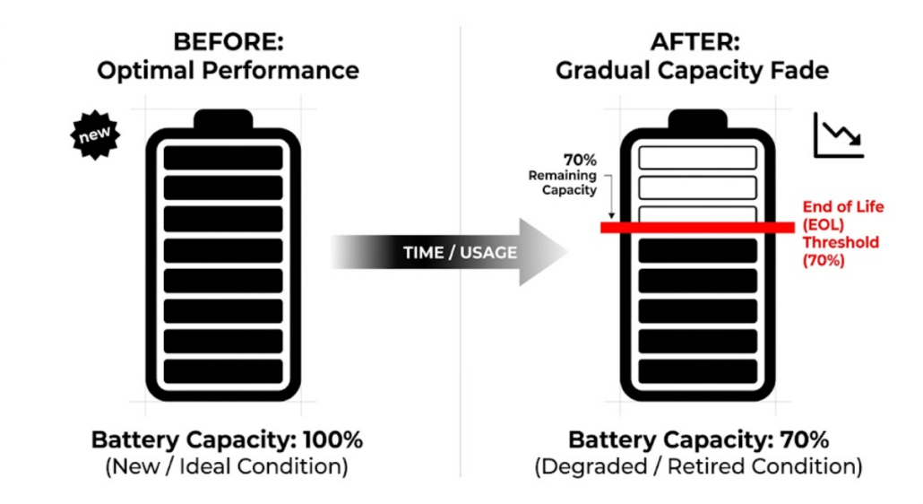
End of Life (EOL) identifies the point when a battery is no longer considered reliable for its primary application.
In most cases, EOL is reached when the SOH drops to 70%–80%. Although the battery still works, its power is much lower. Consequently, you should replace it to keep your system safe and steady.
- EOL = 70%–80% SOH
The battery still works. However, performance is lower. Therefore, it must be replaced.
DOD vs SOH vs EOL in Battery Cycle Standards
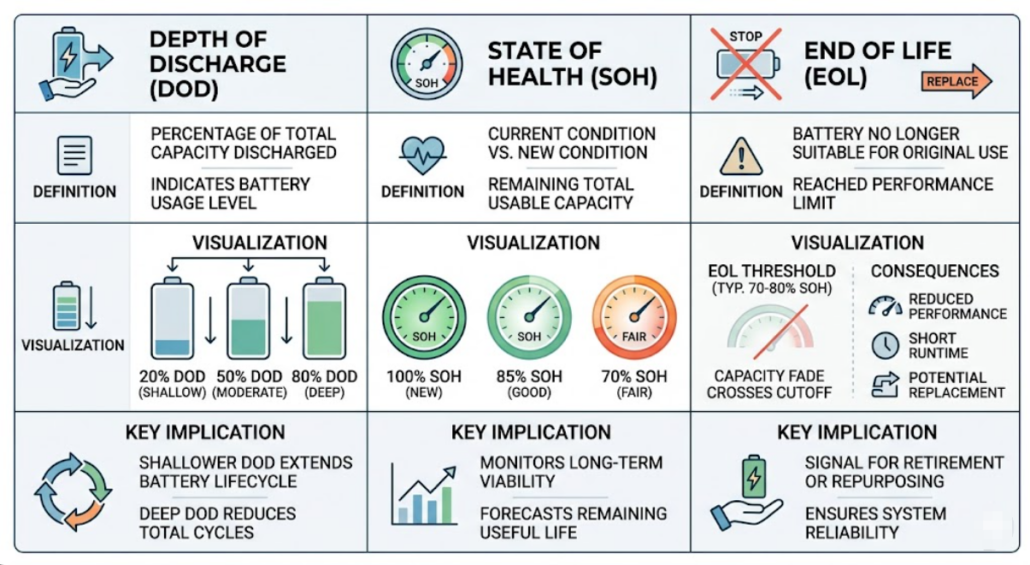
DOD shows usage. SOH shows remaining capacity. EOL shows replacement point.
| Parameter | Meaning | Practical Role | Standard Benchmark |
| DOD | Energy used | Controls daily stress | LFP: 80% / Lead Acid: 50% |
| SOH | Capacity left | Tracks health/aging | 100% (New) to 80% (Aged) |
| EOL | Usability limit | Replacement trigger | Usually 70% or 80% SOH |
Each metric is different. Therefore, you must use all three.
Why Battery Cycle Standards Are Different
Battery cycle standards differ because testing conditions and methods are not the same.
Different Testing Goals in Battery Cycle Standards
ome companies prioritize showing higher cycle numbers for marketing purposes, whereas others focus on providing realistic life expectations for heavy-duty use. Because of this variation in goals, the results across different brands can vary wildly. Therefore, it is crucial to verify if the cycles are rated at high or low temperatures.
Battery Cycle Life Depends on Conditions
Battery life depends on real conditions.
For example:
- High temperature increases wear
- High load adds stress
- Fast charging speeds degradation
Therefore, results change.
Marketing vs Engineering in Cycle Standards
Some data is for marketing. Other data is for engineers.
Marketing materials often highlight the highest possible cycle numbers achieved under perfect lab conditions. In contrast, engineers focus on ‘usable’ life under heavy loads. Because of this discrepancy, it is important to look past the headline numbers and examine the testing parameters instead.”
Because of this, numbers may differ.
Same Battery, Different Ratings
It is common for a single battery to show multiple cycle values depending on the criteria used. Specifically, a manufacturer might list 6,000 cycles at 80% DOD while simultaneously claiming 8,000 cycles if the EOL is set to 70% SOH. Because both ratings are technically correct, you must compare the testing methods instead of just the final numbers.
Application-Based Battery Cycle Standards
Different industries use different metrics.
For example:
- Solar uses EOL
- EV uses SOH
- Backup uses DOD
Therefore, standards change by use case.
Which Battery Cycle Standard Should You Trust?
EOL-based cycle life is the most reliable when tested under real conditions.
However, you must check:
- DOD
- Temperature
- Charge rate
Without this, numbers can mislead.
Simple Rule for Battery Cycle Standards
Always check:
EOL at your real DOD
This gives the most accurate result.
How DOD Affects Battery Cycle Life
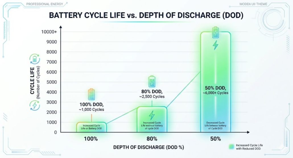
Higher DOD reduces battery life. Lower DOD increases it.
| DOD | Cycle Life |
|---|---|
| 100% | 2,000–3,000 |
| 80% | 3,000–5,000 |
| 50% | 5,000–7,000 |
📊 Datasheet Cycle Life Calibration Tool
Input your battery’s specific datasheet baseline specs to simulate real-world environmental degradation.
*Calculated dynamically via Arrhenius rate parameters for cell aging and exponential Co-efficient models matching LFP structural chemistry metrics.
Therefore, lower DOD improves life.
Lab vs Real Battery Cycle Performance
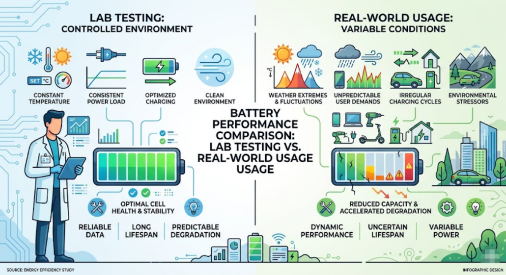
Lab tests typically use ideal conditions to establish a baseline; however, real-life performance is often quite different. For instance, ambient temperature fluctuations and varying discharge loads can add significant stress to the cells. As a result, the actual performance is usually lower than the theoretical ratings found on the datasheet. Consequently, users should plan for a margin of error when sizing their systems
For more details:
- https://www.sciencedirect.com/topics/engineering/cycle-life
- https://www.nrel.gov/docs/fy20osti/74426.pdf
How to Choose Battery Cycle Standards
Always compare DOD, SOH, EOL, and test conditions.
Start with your use case. Then check DOD. Next, review degradation.
Therefore, do not trust cycle numbers alone.
Battery Cycle Standards and Certifications
Battery standards are guided by:
- International Electrotechnical Commission
- Underwriters Laboratories
These groups define safety and testing rules.
Role of BMS in Battery Life
A Battery Management System (BMS) acts as the brain of the energy storage unit by controlling critical environmental and electrical factors.
Specifically, it manages the Depth of Discharge (DOD) and monitors internal temperatures to prevent thermal runaway. Furthermore, by regulating the charging current, the BMS ensures that the cells do not undergo excessive stress.
As a result, the overall battery life improves significantly, allowing the system to reach its full rated cycle potential.
Common Mistakes in Battery Cycle Standards
Many users make mistakes.
Many users make the mistake of trusting cycle numbers without investigating the underlying test conditions. For example, ignoring the DOD or missing the effects of high ambient temperatures can lead to premature system failure. Because of this lack of context, many buyers end up with the wrong battery for their specific climate or load requirements. Therefore, it is essential to review the full datasheet before making a final purchase
How to Improve Battery Life
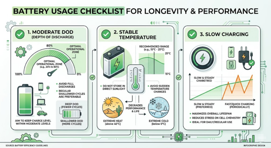
While battery degradation is inevitable, you can extend your system’s lifespan easily by following a few best practices.
For instance, limiting your daily usage to a 70–80% DOD reduces the chemical strain on the Lithium-ion cells. In addition to managing discharge levels, keeping the ambient temperature stable and avoiding frequent fast charging will further preserve the SOH. Consequently, the battery will last much longer than a system that is constantly pushed to its operational limits
Learn More
- Battery Cycle Life Calculator
- How to Read a LiFePO4 Battery Spec Sheet: A Buyer’s Line-by-Line Guide
- Demystifying LiFePO4 Battery Testing: How Manufacturers Grade Their Cells
- BMS SOC Estimation Methods Explained
- Impact of Temperature on LiFePO₄ Batteries Cycle Life
- Battery Management System (BMS) Explained/
- BMS Explained: Real-Time Monitoring, Key Protections, and SOC/SOH Algorithms
FAQs
What is a battery cycle in simple terms?
A battery cycle is one complete discharge and recharge of a battery’s rated capacity. It does not have to happen in a single sitting; for example, using 50% of your battery today and 50% tomorrow counts as exactly one full cycle.
How does DOD affect total battery life?
DOD (Depth of Discharge) has an inverse relationship with lifespan. Lowering your daily DOD significantly increases the total number of cycles a battery can perform. For instance, a Lithium (LFP) battery might achieve 3,000 cycles at 100% DOD but over 6,000 cycles if limited to 80% DOD.
What is the difference between SOH and SOC?
SOC (State of Charge): Tells you how much “fuel” is in the tank right now (0% to 100%).
SOH (State of Health): Tells you how much the “tank” has shrunk over time due to aging (e.g., 90% SOH means the battery can now only hold 90% of its original design capacity).
When should I replace my battery (EOL)?
The industry standard for End of Life (EOL) is 80% SOH. While the battery will still function below this point, it will drain faster and may struggle to power high-surge appliances. In solar storage, 80% is the typical threshold for warranty claims and reliable performance.
Final Takeaway
Battery Cycle Standards are not simple numbers. Instead, they depend on use and conditions.
Therefore, always check:
- DOD
- SOH
- EOL
Always review full test conditions before comparing batteries.
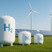
Green Hydrogen Storage: How We Store the Fuel of the Future
Green hydrogen storage is a hot topic in the clean energy world. As more industries look to hydrogen as a zero-carbon fuel, knowing how to store it safely and efficiently becomes just as important as making it.
In this post, we’ll break down what green hydrogen is, why storage matters, how it’s done, and what challenges we face in storing this promising fuel.
What Is Green Hydrogen?
Before we talk about green hydrogen storage, let’s understand what green hydrogen is.
Hydrogen is the most abundant element in the universe. But on Earth, we have to produce it because pure hydrogen gas doesn’t exist naturally.
Green hydrogen is made by using renewable electricity (like solar or wind) to split water into hydrogen and oxygen. This process is called electrolysis. Because no fossil fuels are used, green hydrogen has zero carbon emissions at the point of production.
Why Is Green Hydrogen Storage Important?
Hydrogen is light and energy-dense by weight, but it takes up a lot of space by volume. So, storing it efficiently is crucial for:
- Using it when renewables aren’t available (like at night or on windless days)
- Transporting it to where it’s needed — for fuel cells, power generation, or industry
- Stabilizing supply and demand in hydrogen markets
Safe and reliable green hydrogen storage unlocks hydrogen’s true potential.
How Is Green Hydrogen Stored?
There are a few main ways to store green hydrogen. Let’s look at the most common ones:
1. Compressed Gas Storage
This is the simplest and most common method today.
Hydrogen gas is compressed to high pressures — typically 350–700 bar — and kept in special high-pressure tanks.
Pros:
- Mature technology
- Relatively low cost for small-to-medium storage
Cons:
- Requires strong, heavy tanks
- Energy needed for compression
2. Liquid Hydrogen Storage
Hydrogen can be cooled to −253°C to become a liquid.
Storing hydrogen as a cryogenic liquid reduces its volume about 800 times compared to its gaseous state.
Pros:
- High storage density
- Useful for large-scale transport (e.g., shipping)
Cons:
- Expensive to chill hydrogen to these temperatures
- Boil-off losses due to heat leaks
3. Materials-Based Storage (Solid Storage)
Another method is storing hydrogen in solid materials — like metal hydrides or chemical carriers.
Hydrogen binds with certain metals or chemicals and can be released when needed.
Pros:
- High safety level (low pressure)
- Compact storage
Cons:
- Expensive materials
- Slow hydrogen release rates
Where Is Green Hydrogen Storage Used?
- Energy Storage: Store excess renewable energy in the form of hydrogen.
- Transport: Fuel for hydrogen cars, trucks, buses, and even planes.
- Industry: For steelmaking, ammonia production, or backup power.
- Grid Stability: Balance supply and demand in renewable grids.
Key Challenges in Green Hydrogen Storage
While the technology is promising, there are still hurdles:
✅ High costs of compression, liquefaction, or materials
✅ Safety concerns (hydrogen is highly flammable and leaks easily)
✅ Lack of storage infrastructure in many places
✅ Energy losses during storage and retrieval
Researchers and companies worldwide are working to make green hydrogen storage safer, cheaper, and more efficient.
The Future of Green Hydrogen Storage
With more investment and innovation, the future looks bright.
We may see new storage technologies — like underground hydrogen caverns, advanced metal hydrides, or organic liquid carriers — that help us store large amounts of hydrogen cost-effectively.
One thing is clear: green hydrogen storage will play a big role in our move toward a carbon-free energy future.
Final Thoughts
Green hydrogen has huge potential to decarbonize industries, transport, and power. But producing it is only half the battle — storing it is the key to unlocking its full promise.
As technology improves, we’ll see better, safer, and more affordable ways to store green hydrogen, making it a real fuel for the future.
FAQs About Green Hydrogen Storage
Q1: Is storing green hydrogen dangerous?
Hydrogen is flammable and can leak easily, so storage systems must follow strict safety standards. Modern storage tanks and systems are designed with multiple safety layers.
Q2: Can hydrogen be stored underground?
Yes! Underground salt caverns and depleted gas fields are being explored as large-scale, low-cost options for bulk hydrogen storage.
Q3: Is green hydrogen storage expensive?
Currently, storage costs can be high, especially for liquid or solid storage. But with more research and scaling up, costs are expected to come down.
Q4: Why not use batteries instead?
Batteries are great for short-term storage, but hydrogen is better for storing large amounts of energy for long periods, like seasonal energy storage.
Ready to Learn More?
Want to keep up with the latest on green hydrogen and clean energy storage?
Subscribe to our blog or contact us to see how hydrogen solutions could power your future projects!
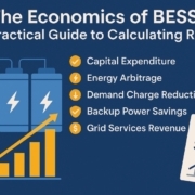
The Economics of BESS: A Practical Guide to Calculating ROI
Battery Energy Storage Systems (BESS) are a smart solution for businesses that want to cut electricity costs, avoid peak charges, and get more from renewable energy. But before you invest, you must know the economics of BESS — and how to calculate your Return on Investment (ROI).
This guide explains the costs, savings, and key steps to help you decide if a BESS makes good financial sense for your business or large-scale project.
What Does a BESS Cost?
Understanding BESS costs is the first step in calculating ROI. Here’s what’s involved:
✔️ Capital Expenditure (CAPEX)
- Battery modules (like lithium-ion, sodium-ion, or flow batteries)
- Inverters or Power Conversion Systems (PCS)
- Energy Management Systems (EMS) and Battery Management Systems (BMS)
- Installation and grid connection fees
✔️ Operating Expenditure (OPEX)
- Regular inspections and maintenance
- Software updates and monitoring fees
- Insurance costs
- Replacements for battery modules or inverters over time
✔️ End-of-Life Costs
- Decommissioning and recycling fees
How BESS Saves or Earns You Money
The economics of BESS depend on how much you can save or earn over time.
⚡ Energy Arbitrage
Store energy when it’s cheap and use or sell it when prices spike.
⚡ Demand Charge Reduction
Cut peak demand charges by using stored energy during expensive hours.
⚡ Backup Power Savings
Avoid costly downtime during blackouts.
⚡ Grid Services Revenue
Some businesses earn money by helping stabilize the grid.
⚡ Renewable Energy Integration
Store surplus solar or wind energy instead of wasting it.
The Economics of BESS: Steps to Calculate Your BESS ROI
Here’s a clear, practical way to work out if BESS is worth it for you:
✅ 1. Define Your Project
- System size (kWh/kW)
- Expected charge/discharge cycles
- BESS Round Trip Efficiency (RTE)
- Local energy rates and demand charges
✅ 2. Estimate Total Costs
- Gather quotes for equipment, installation, and grid connection.
- Include yearly O&M costs for the entire lifespan.
✅ 3. Project Savings and Revenue
- Use your energy data to estimate savings from lower peak charges.
- Check if your area pays for grid services.
- Add any government incentives or tax credits.
✅ 4. Build a Simple Cash Flow
- Compare annual costs vs. annual savings/revenue.
- Run it for the entire expected lifespan (typically 10–20 years).
✅ 5. Calculate Payback Period and ROI
- Payback Period = Total Investment ÷ Annual Net Savings
- ROI = [(Total Net Savings – Total Cost) ÷ Total Cost] × 100%
Example:
If your BESS costs $400,000 and saves you $80,000 per year, your payback is 5 years. If the system lasts 15 years:
($80,000 × 15 – $400,000) ÷ $400,000 × 100% = 200% ROI.
Higher BESS RTE directly improves a Battery Energy Storage System’s (BESS) Return on Investment (ROI) by maximizing usable energy, reducing operational costs, and shortening the payback period. Because RTE measures the ratio of energy discharged to energy charged, even a 1% increase in efficiency can significantly impact lifetime revenue at grid scale.
The Economics of BESS: Tips for Better BESS ROI
✔️ Be realistic: Use conservative savings estimates.
✔️ Factor in battery aging: Storage capacity drops over time.
✔️ Know your local policies: Incentives vary by country or state.
✔️ Get expert help: A reliable consultant can build a strong financial model.
“Before calculating ROI, get your realistic cycle life estimate using our Battery Cycle Life Calculator.”
Final Thoughts
The economics of BESS can make a huge difference to your bottom line. Taking time to calculate your ROI properly helps you invest wisely and unlock long-term savings. For businesses serious about energy resilience and cost control, BESS can be a profitable piece of your energy strategy.
Frequently Asked Questions (FAQ) about The Economics of BESS
Q1: What’s a typical payback period for BESS?
A: Many businesses see a 5–7 year payback, but it depends on system size, local energy costs, and incentives.
Q2: Do BESS really last 15 years?
A: Good-quality BESS can last 10–20 years with proper maintenance, but performance slowly degrades.
Q3: Can I get tax credits for BESS?
A: Some regions offer grants, rebates, or tax credits. Check your local government’s energy programs.
Q4: Is BESS only for big companies?
A: Not at all! Small businesses, farms, and communities can benefit too — especially when paired with renewables.
Q5: Is BESS better suited for businesses with renewable energy?
A: Yes! Pairing BESS with solar or wind generation maximizes savings by storing excess energy for use during non-generating hours.
Q6: Are there any hidden costs in BESS projects?
A: Sometimes, grid interconnection fees, software subscriptions, or unexpected permitting costs can arise. Always add a contingency buffer.