

BESS Inrush Current: Motor Starting and Transformer Energization
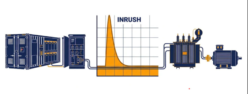
BESS inrush current is the brief surge that a motor start or transformer energization pulls from a battery system. A battery inverter has far less overcurrent margin than a generator, so designers manage the surge instead of supplying it.
Start a large induction motor and the supply sees a short demand far above normal running current. Energize an unloaded transformer and the same thing happens.
A synchronous generator can supply that surge. Its machine design and excitation system give it strong short-time current.
A battery power conversion system (PCS) is different. Its semiconductor converters have tight thermal and switching limits, so short-time overcurrent is small, as this NLR black-start study shows.
Managing BESS inrush current is therefore less about delivering the surge. It is more about not having to deliver it.
This guide explains why motor and transformer inrush differ. Then it covers the research, a real field test and the design methods that make it work.
BESS Inrush Current in Brief
Quick answer: A typical BESS cannot supply the 6–8× locked-rotor current of a direct-on-line motor start. It also cannot supply the 10×+ inrush of an unfavorably energized transformer. Its PCS has limited short-time current. Designers therefore manage BESS inrush current with voltage ramps, current limits, soft starters and sizing.
Why BESS Inrush Current Is Hard for a Battery Inverter
BESS inrush current is hard to handle because an inverter has very little spare current. Three points explain why.
Limited Overcurrent Capability
Research on grid-strengthening inverters notes that their overcurrent limit is far smaller than that of synchronous machines [4]. That weakens voltage support and protection.
It also makes motor starting and transformer energizing hard [4].
The reasons are semiconductor physics and cost. Power devices have heat limits.
Cost-driven sizing also leaves only 5% to 20% current headroom in grid-forming inverters [5].
In a typical medium-voltage design, the device current rating has little margin above maximum load current. If current passes the limit, the converter may cut output, enter a protection state or trip [2].
The black-start study notes that engineers commonly design inverters for no more than about 1.2 times rated current. It uses 1.2 pu as its main case [1].
Real PCS short-time ratings vary by maker, design, cooling and duration.
The Current Limiter Shapes the Outcome
The limiter matters as much as the number. A 2024 IEEE review notes that some events push an inverter into overcurrent.
Motor-start inrush, cold-load pickup and black start are examples [3].
When that happens, the limiter overrides normal control. It then decides how the inverter acts during and after the event.
That is why BESS inrush current depends on limiter design [3].
When BESS Inrush Current Becomes a Problem
One scoping point avoids confusion. When a BESS follows a stiff grid, the grid supplies most of the inrush.
BESS inrush current is then a minor issue.
The problem appears when the BESS forms the voltage. Examples include islanded microgrids, backup power and black start.
It also appears when the BESS itself energizes a transformer or starts a motor. Our guide to grid-forming vs. grid-following BESS explains the two control modes.
Induction Motor Starting: What BESS Inrush Current Looks Like
A direct-on-line motor start creates the largest BESS inrush current at most industrial sites. Current and torque behave very differently, and that gap drives the problem.
Locked-Rotor Current and Torque
An induction motor at standstill looks like a low-impedance, mostly reactive load. Connected directly at rated voltage, it draws locked-rotor current.
The black-start study puts this at six to eight times rated current, depending on design [1].
IEC 60034-12 sets locked-rotor current and apparent-power limits by motor design class [8]. The 1.5 MW motor in the study drew 6.1 times rated current [1].
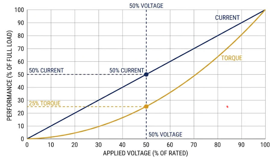
At locked rotor, the motor acts roughly like a constant impedance. Current scales with applied voltage, but torque scales with its square.
That is the core problem. If a current-limited inverter lets voltage sag, torque falls much faster than current.
Halve the voltage and current halves, but torque drops to a quarter.
What the NLR Simulation Shows
The National Laboratory of the Rockies (formerly NREL) simulated a 1.5 MW motor. The motor started through transformers and a line from a current-limited grid-forming inverter [1].
| Case | Inverter current limit | Result |
|---|---|---|
| Unloaded start | 10× rated (effectively unrestricted) | Motor reaches 95% speed in about 1.9 s; about 4× rated rms current drawn |
| Unloaded start | 1.2× rated | Starts, but terminal voltage sags to about 0.3 pu and the start takes about 20 s |
| Load torque present at start | 1.2× rated | Motor does not start |
| Load applied after the motor reaches steady state | 1.2× rated | Motor stalls |
| Same case, limit raised | 1.5× rated | Motor sustains the load |
| Voltage-ramp soft start | Current held at or below rated (inverter rated to match the motor) | Inrush eliminated; motor sustains load applied afterward |
| Three inverters in parallel | Each 1.2× rated | Starts in about 3.4 s if load is applied after the start; if loaded at the start, it settles at very low speed in the motor’s unstable region |
Two lessons follow. First, a current-limited inverter can start a large motor only without load, or with the load added later.
The start also takes far longer.
Second, a controlled voltage ramp or more inverters sharing current helps far more than tolerating the sag [1].
A separate study saw a similar pattern. Its current-limited source started an unloaded motor only after more than 20 seconds, with terminal voltage near 0.3 pu [4].
Other work compares starting methods for grid-forming microgrids [6].
These are simulation results for one motor, with no friction torque modeled. The authors call for hardware validation [1].
Transformer Energization: A Different Kind of BESS Inrush Current
Transformer inrush is not a load demand. It is magnetic saturation, so BESS inrush current follows different rules than in a motor start.
Core flux is the time integral of applied voltage. Inrush therefore depends on the flux left in the core.
It also depends on the point in the voltage wave when the transformer connects [7].
In the worst case, peak flux approaches the residual flux plus twice the normal maximum flux. That is far beyond the saturation level [2].
The magnetizing impedance collapses and the current spikes.
The resulting current can exceed ten times nominal transformer current for four to six cycles [2].
Sympathetic inrush happens when one transformer energizes while others are live. Its peak is lower, but it can last for seconds [2].
A BESS that energizes a feeder with many distribution transformers sees the sum.
Two levers limit transformer inrush: choose the connection instant, or reduce the voltage amplitude [2]. The first is point-on-wave switching.
Point-on-wave switching is often impractical in a BESS-led restoration. It needs breaker control and transformer data.
It also needs flux knowledge and operator teamwork [2].
That leaves the second lever, and a voltage-source inverter can pull it in its control loops. Network studies, like those in our BESS grid connection studies guide, help confirm the sequence of BESS inrush current events.
Five Ways to Manage BESS Inrush Current
Designers combine control, load-side starting methods and sizing to manage BESS inrush current. These five layers work together.
Limit Current Inside the Control Loop
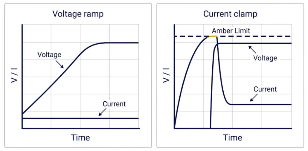
The first layer is protection by design. A voltage-loop reference modifier acts when current nears a high level.
That level sits above continuous rating but below the protection trips.
It cuts the current reference to a limit within the continuous rating. Then it releases once current falls back.
Because a limiter can saturate the controller, the voltage controller needs anti-windup [2].
Review literature stresses that limiter design shapes behavior during motor starts, cold-load pickup and black start [3]. See also our guide to PCS functions and features.
Ramp the Voltage for Soft Energization
Ramping output voltage lets transformer flux build gradually. It also keeps motor current near rated.
A rate limiter on the voltage reference in the droop loop does this.
In the NLR simulation, the ramp removed the inrush current [1]. Treat that as a simulated result.
A ramp limits volt-seconds and so core saturation, but a real transformer may still draw some magnetizing current.
The trade-off is grid code. Some network operators prefer voltage inside the normal band, for example 0.90–1.05 pu [2].
Our BESS grid codes and compliance guide covers this.
Clamp Instead of Ramp When the Grid Needs Nominal Voltage
Sometimes the grid needs nominal voltage at once. In that case, the reference modifier can hold current at the inverter’s maximum.
The transformer then saturates and recovers. Field results support this way to limit BESS inrush current, as the next section shows.
Reduce the Demand on the Load Side
Motors do not have to start across the line. A variable-frequency drive or soft starter lowers the line current at start.
Staggering transformer energizing also keeps their inrush currents from adding up.
A plain reduced-voltage start costs torque. Torque falls roughly with the square of applied voltage.
Under a constant-impedance model, it falls with the square of the current cut. Heavy loads therefore need a method that keeps torque up.
Size, Parallel or Augment the Source
More PCS rating supplies more current. In the NLR study, three parallel units, each limited to 1.2×, raised terminal voltage and cut start time sharply [1].
Higher-overcurrent hardware is another route. One proposal pairs the inverter with a nearby synchronous condenser that supplies the high current [4].
Condenser-style controls also aim to meet tough grid-code current rules [5].
This table compares the five approaches.
| Strategy | Best suited to | Main trade-off |
|---|---|---|
| Control-loop current limit | Transformer energization at nominal voltage | Needs correct anti-windup design; brief current clamp |
| Voltage ramp | Black start, motor start, feeder energization | May conflict with operator voltage-band rules |
| Load-side soft start or drive | Motors | Added equipment; torque trade-off for simple reduced-voltage starters |
| Sequenced energization | Multi-transformer feeders | Longer restoration time |
| Larger or paralleled PCS, or synchronous condenser | Large motors, weak islands | Capital cost |
Field Evidence: A 1 MVA BESS Energizing a 20 kV Network
Researchers at the University of Vaasa tested BESS inrush current controls on a real network in Ingå, Finland [2]. A 1 MVA BESS, built from four parallel inverter units, energized a 20 kV network.
It also supplied a 250 kW load.
The network served around 400 customers and about 30 distribution transformers, totaling roughly 2.5 MVA. The team tested two schemes.
First, the team used a voltage-reference rate limiter in the droop loop. The inverter ramped the network voltage, and the output current showed none of the typical inrush overcurrent.
Second, the team used a current-reference modifier in the voltage loop. The inverter applied nominal voltage at once.
An inrush peak began to form on closing, but current fell fast once the inverter reacted.
Then the event ended in under 20 ms, and no recurring, decaying inrush pattern appeared. Nominal voltage reached the medium-voltage bus in less than half a cycle [2].
The authors conclude that the approach avoids oversizing the inverter for inrush. It also works without knowing transformer data, breaker timing or network layout [2].
This result covers one medium-voltage network and one set of transformers. It is not a guarantee for every feeder layout, transformer size or residual-flux condition.
Still, it shows that control can manage sympathetic transformer inrush in at least that case.
Worked Example: Sizing a PCS for BESS Inrush Current
This example is simple arithmetic, not sourced data. It shows how BESS inrush current sets PCS size.
Setup and Results
Take a 160 kW, 400 V motor. Its full-load current (FLC) is about 276 A, assuming 0.95 efficiency and 0.88 power factor.
The PCS can supply 1.2 times rated current. How large must it be if it carries the whole starting current?
| Starting method | Peak line current | Approx. start kVA at 400 V | PCS rating needed at 1.2 pu | Relative starting torque (DOL = 100%) |
|---|---|---|---|---|
| Direct on line (6.5× FLC) | about 1,800 A | about 1,245 | about 1,040 kVA | 100% |
| Soft starter limited to 3× FLC | about 830 A | about 575 | about 480 kVA | about 21% (current ratio squared) |
| Drive limited to 1.5× FLC | about 415 A | about 287 | about 240 kVA | Depends on method and control (see note below) |
What the Ratio Tells You
The lesson is the ratio. The motor’s running load is about 191 kVA, and a direct start demands about 6.5 times that at the terminals.
That means a PCS roughly 5.4 times the running kVA once a 1.2 pu limit applies.
A drive limited to 1.5× FLC cuts the demand to about 1.5 times the running kVA. The PCS then needs only about 1.25 times the running kVA.
Starting current is largely reactive. The limit is therefore the PCS current rating, not battery energy, and adding battery modules does not raise it.
For a wider sizing method, try our C&I BESS sizing calculator.
Check the PCS datasheet for overload size and duration, because 1.2 pu may last only seconds. Figures are three-phase line values.
PCS sizing must also cover reactive current, not just real power.
Take overload ratings, reactive current and allowed voltage sag from the PCS datasheet and project study.
Torque percentages are relative to direct-on-line starting, not to rated torque. For a simple reduced-voltage starter, torque falls roughly with the square of applied voltage.
A drive’s torque depends on its control method, its low-frequency voltage boost and whether it uses closed-loop vector control.
Specification Checklist for BESS Inrush Current
Use this checklist to specify BESS inrush current performance before you buy. Each item ties to a source above.
- Overcurrent rating: Ask for PCS overcurrent in grid-forming mode as a per-unit value with duration. Also ask what the controller does at the limit [3].
- Soft-start function: Require a voltage ramp or equivalent for energizing transformers and starting motors. Then confirm the network operator’s voltage-band tolerance [2].
- Transformer data: List every transformer to energize, with rating, impedance and sequence. This lets you assess sympathetic inrush [2].
- Motor data: Get the locked-rotor current ratio or kVA, the load-torque curve and the inertia. Then choose a drive or soft starter [8].
- Protection: Study relays on the cranking path, since inverter fault current is small. Check motor heat protection too, because current-limited starts run long [1]. See our guide to BESS short circuit protection.
- Validation: Confirm with electromagnetic-transient simulation and a site or factory test [1].
Limits and Open Questions for BESS Inrush Current
Much of the evidence on BESS inrush current from motors comes from simulation. It assumes ideal current sharing between inverters and no friction torque [1].
Voltage ramping may not suit every network operator [2]. Grid codes also keep changing.
Current-limit design is now central to grid-forming BESS specs [3].
Treat any vendor claim of “unlimited motor starting” with skepticism. First ask for the overcurrent rating, the duration and the test conditions.
For generator comparisons, see our guide to diesel generator replacement with BESS.
Frequently Asked Questions About BESS Inrush Current
These answers cover the most common BESS inrush current questions from project engineers.
Can a BESS start a large motor directly on line?
Only if its PCS short-time current rating, voltage support and protection settings allow it. With a 1.2× limit, the simulated motor could not start under load [1].
Does a bigger battery reduce BESS inrush current?
Not by itself. BESS inrush current is a current (kVA) problem, not an energy (kWh) problem.
More PCS rating, paralleled inverters or a soft-start method raise the limit [1].
Why not use controlled switching for transformers?
It needs breaker control plus knowledge of transformer parameters and residual flux. A BESS usually lacks both on a network it does not own [2].
Does this matter for grid-connected systems?
Mostly when the BESS forms the voltage. When it follows a stiff grid, the grid supplies most of the BESS inrush current.
Further Reading from SunLith
These SunLith guides add context on BESS inrush current, controls and system design.
- Grid-forming vs. grid-following BESS
- BESS PCS functions and features
- Microgrid BESS
- BESS grid connection studies
- BESS short circuit protection
- BESS grid codes and compliance
- C&I BESS sizing calculator
References
These sources support the BESS inrush current figures in this article.
1. H. Jain, G.-S. Seo, E. Lockhart, V. Gevorgian, B. Kroposki, “Blackstart of Power Grids with Inverter-Based Resources,” 2020 IEEE PES General Meeting, pp. 1–5, DOI 10.1109/PESGM41954.2020.9281851. Figures are from the NLR preprint NREL/CP-5D00-75327 (National Laboratory of the Rockies, formerly NREL). https://www.nlr.gov/docs/fy20osti/75327.pdf
2. M. Shahparasti, H. Laaksonen, K. Kauhaniemi, P. Lauttamus, S. Strandberg, J. Strandberg, “Inrush Current Management During Medium Voltage Microgrid Black Start with Battery Energy Storage System,” IEEE Access, 2022, DOI 10.1109/ACCESS.2022.3167701. https://doi.org/10.1109/ACCESS.2022.3167701
3. N. Baeckeland, D. Chatterjee, M. Lu, B. Johnson, G.-S. Seo, “Overcurrent Limiting in Grid-Forming Inverters: A Comprehensive Review and Discussion,” IEEE Transactions on Power Electronics, vol. 39, no. 11, pp. 14493–14517, Nov. 2024, DOI 10.1109/TPEL.2024.3430316. https://doi.org/10.1109/TPEL.2024.3430316
4. H. Li, C. Nie, F. Wang, “Grid Strengthening IBR: An Inverter-Based Resource Enhanced by a Co-Located Synchronous Condenser for High Overcurrent Capability,” IEEE Open Journal of Power Electronics, vol. 3, pp. 535–548, 2022, DOI 10.1109/OJPEL.2022.3194849. https://doi.org/10.1109/OJPEL.2022.3194849
5. J. Freytes, A. Rossé, V. Costan, G. Prime, “Grid-Forming Control Based on Emulated Synchronous Condenser Strategy Compliant with Challenging Grid Code Requirements,” arXiv preprint arXiv:2303.00391, v2, last revised 7 May 2024. https://arxiv.org/abs/2303.00391
6. V. Patil, S. Mishra, A. Singhal, “Investigating the Impact of Induction Motor Starting on Grid-Forming Inverter-Based Microgrid,” 2024 IEEE PES ISGT Asia, Bengaluru, India, pp. 1–6, DOI 10.1109/ISGTAsia61245.2024.10876368. https://doi.org/10.1109/ISGTAsia61245.2024.10876368
7. B. C. Sung, S. Kim, “Accurate Transformer Inrush Current Analysis by Controlling Closing Instant and Residual Flux,” IPST 2023, paper 23IPST014.
8. IEC 60034-12:2016, Rotating electrical machines, Part 12: Starting performance of single-speed three-phase cage induction motors.