
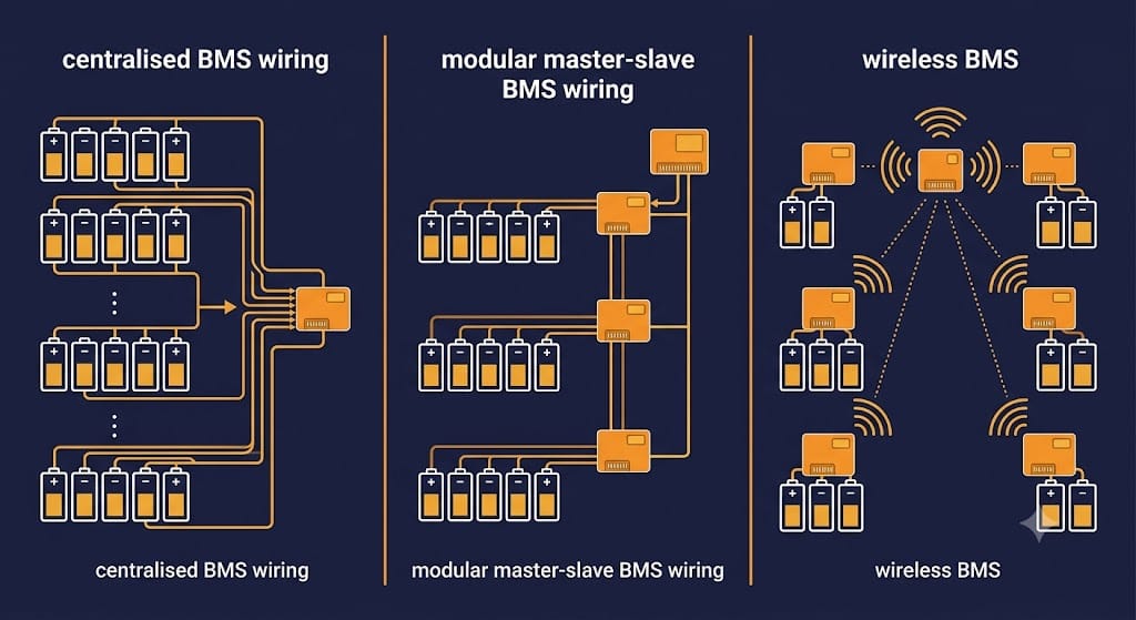
BMS Architecture Explained: Centralised vs Modular (Master-Slave) vs Wireless BMS for BESS
| ⚡ Quick Answer: Which BMS Architecture Is Right for a BESS? BMS architecture comes in three main types: centralised (one controller handles all cells directly), modular master-slave (each module has its own slave BMS reporting to a master), and wireless BMS (modules communicate without a physical data harness). Centralised suits small residential systems. Modular master-slave is the standard for commercial and utility-scale BESS. Wireless BMS is maturing fast in EVs but remains early-stage for grid-scale BESS, mainly due to EMI risk in high-power environments and a 25-40% cost premium. |
1. Why BMS Architecture Matters Beyond Just System Size
Most guides treat BMS architecture as a simple size question: small systems get one BMS, big systems get many. That is true as a starting point. But the choice also decides how a fault in one module affects the rest of the pack, how much wiring a technician has to run and maintain, and how easily the system scales later without a redesign.
For the basics of what a BMS does — monitoring, protection, balancing, and communication — see our complete battery management system guide. This article goes one level deeper: the wiring topology inside modular designs, and the wireless BMS option now entering the market.
2. Centralised BMS: How a Single Controller Works
In a centralised design, one controller connects directly to every cell in the pack. It handles voltage monitoring, balancing, and protection for all cells from a single board. There is no master-slave hierarchy here, simply because there is only one controller.
This setup keeps cost and complexity low. As a result, it works well for residential systems under roughly 100 kWh. Cell counts here typically stay in the range of a few dozen to a few hundred. Beyond that range, though, the wiring harness needed to connect every single cell to one board becomes heavy, expensive, and hard to service.
A centralised design also has a single point of failure built in. If the central controller fails, the entire pack loses monitoring and protection at once. For small systems, this risk is usually acceptable, given the lower stakes and lower cost. For larger systems, however, it is not.
3. Modular (Master-Slave) BMS Architecture: How It Works
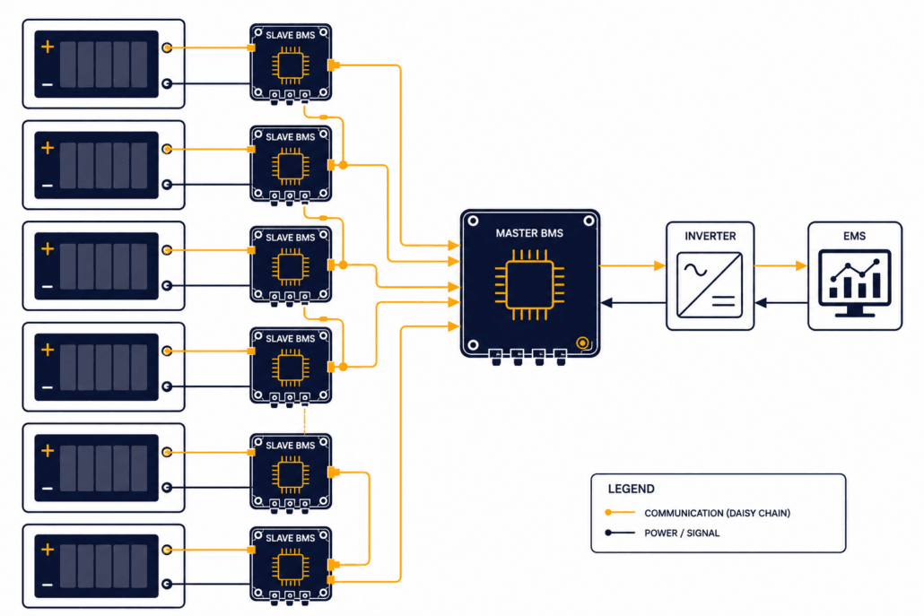
A modular design, often called master-slave, splits the job across many controllers instead of one. Each battery module gets its own slave BMS board. That slave handles local cell monitoring and balancing for its own module only. In turn, all slave boards report up to a central master BMS, which coordinates the full pack and talks to the inverter and EMS.
This setup scales far better than a centralised design. For instance, adding another module usually means adding another slave board to the daisy chain, not redesigning the whole harness. As a result, it is the standard choice for commercial and utility-scale BESS today.
The real engineering decision here, though, is not whether to use master-slave. Most large systems already do. Instead, it comes down to which wiring protocol connects the slaves to the master. It also depends on how much independence each slave keeps if it loses contact with the master.
4. Wiring Protocols in Modular Designs: isoSPI vs CAN vs LIN
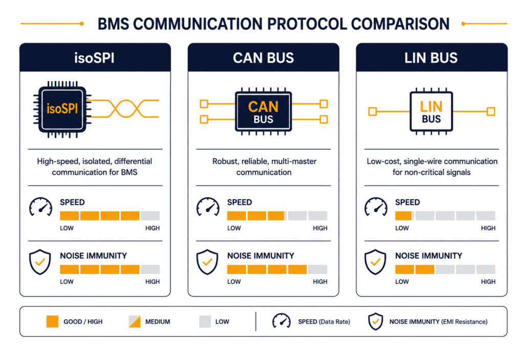
Three communication protocols dominate the physical link between slave boards and the master. Each one makes a different tradeoff between speed, noise immunity, and cost. For a deeper look at how these networks manage data across the entire system, read our guide on BESS communication protocols.
- isoSPI — an isolated version of SPI (Serial Peripheral Interface), built specifically for daisy-chaining BMS slave boards. It runs over a simple twisted pair. It tolerates the electrical noise inside a battery pack well, and it supports fast data rates. As a result, many premium BMS platforms use isoSPI for the slave-to-slave and slave-to-master link inside one rack.
- CAN bus — the same protocol widely used in automotive and industrial systems. CAN is robust, well standardized, and easy to integrate with third-party inverters and EMS platforms. Because of this, it is common for the master-to-inverter and master-to-EMS link, and sometimes for slave-to-master links in simpler designs.
- LIN bus — a lower-cost, lower-speed protocol used for less time-critical links, such as temperature sensor networks within a module. In short, it trades speed for lower wiring and component cost.
In practice, many BESS platforms combine protocols. isoSPI handles fast, noise-resistant slave communication within a rack. CAN bus then takes over at the master level for system-wide integration. Ask your supplier which protocol handles which link. Otherwise, a design built entirely on one lower-speed protocol may struggle to keep up with fast balancing or protection response at scale.
5. Wireless BMS Architecture: How It Works and Where It Stands Today
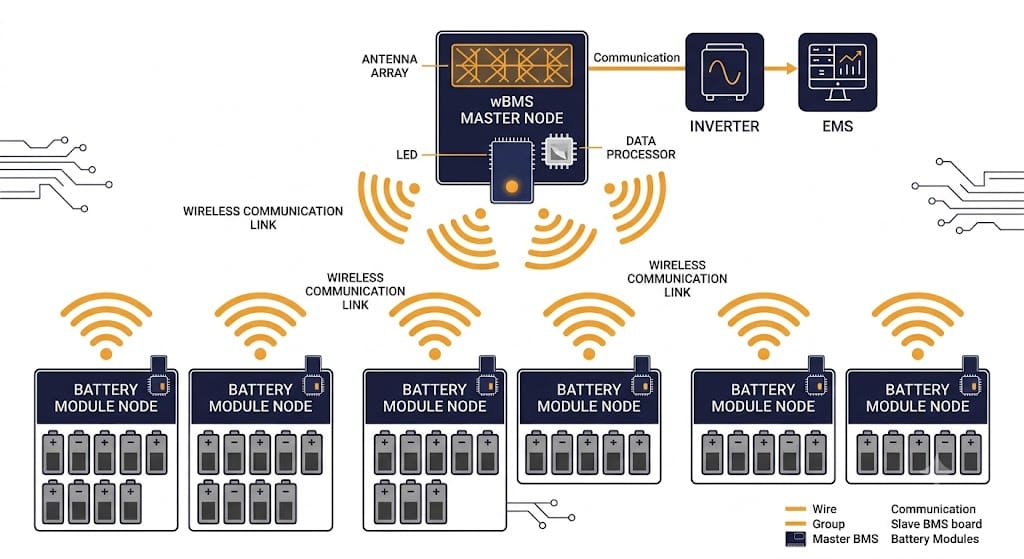
Wireless BMS removes the physical data harness between modules entirely. Instead of isoSPI or CAN wiring, slave boards communicate with the master using Bluetooth Low Energy, Zigbee, or a proprietary 2.4GHz radio protocol. Cell voltage, temperature, and balancing commands all travel wirelessly instead of over copper.
Why Wireless BMS Is Appealing
The appeal is real. Going wireless removes the weight, cost, and failure points of a physical wiring harness. It also simplifies manufacturing, since there are fewer connectors to install and fewer wiring faults to test for. This matters most where running a wired harness is expensive or awkward. Second-life BESS built from repurposed EV modules, for example, often have mismatched connector layouts that make wiring harder than usual.
Why Utility-Scale BESS Isn’t There Yet
That said, wireless BMS is not yet the default choice for grid-scale BESS, and current research explains why. A peer-reviewed review of wireless BMS technology, published in MDPI Energies, notes that wireless systems remain at an early stage of maturity. This is especially true for high-power settings, where electromagnetic interference from PCS switching can disrupt the link.
Three practical concerns keep wireless BMS out of most utility-scale BESS today. First, EMI susceptibility: high-power switching from inverters and PCS equipment can interfere with the wireless signal. That kind of interference in a safety-critical monitoring link is a serious risk, not a minor inconvenience. Second, cost: wireless hardware currently runs 25-40% more than equivalent wired systems, which matters a great deal at grid scale. Third, standardization: there is no universal wireless protocol yet. As a result, mixing components from different makers is harder than it is with wired isoSPI or CAN systems.
For now, wireless BMS is furthest along in electric vehicles, where weight savings translate directly into range. It is also gaining ground in residential solar-plus-storage products, where simple assembly and remote installation flexibility matter more than they do at utility scale. For grid-scale BESS specifically, expect wired modular designs to stay the standard for the next several years. Wireless will likely enter first through pilot projects and second-life storage deployments.
6. Comparing Centralised, Modular, and Wireless BMS Architecture Options
| Factor | Centralised | Modular (Master-Slave) | Wireless |
|---|---|---|---|
| Typical system size | Under 100 kWh | 100 kWh to multi-MWh | EVs, residential ESS today; utility-scale still early |
| Wiring complexity | High at scale — every cell wired to one board | Moderate — daisy-chained per module | Minimal — no data harness |
| Failure isolation | Poor — single point of failure | Good — slave boards can protect locally | Depends on link redundancy design |
| Cost | Low | Moderate, scales predictably | 25-40% premium over wired today |
| Maturity for BESS | Proven, residential standard | Proven, commercial/utility standard | Early-stage for grid-scale |
7. Failure Isolation: The Real Safety Question Behind the Design
The most important question about any BMS design is not which protocol it uses. Instead, it is what happens when one part of the system fails. In a well-designed modular setup, each slave board keeps protecting its own module even if it loses contact with the master. This relies heavily on the local execution of core BMS algorithms
to calculate state-of-charge (SOC) and state-of-health (SOH) independently. In a poorly designed system, however, the whole pack’s protection depends entirely on the master controller.
Evaluating these single points of failure is a core part of rigorous risk assessment. For a deeper look at how engineers map out these risks and establish safety goals, see our guide on BMS functional safety, HARA, and FMEA.
So ask your supplier directly: if the master BMS fails or loses communication, does each module still enforce its own voltage and temperature limits? If the answer is no, that design has a hidden single point of failure, no matter how many slave boards it has.
8. Choosing the Right BMS Architecture for Your BESS Project
For residential and small commercial systems under 100 kWh, a centralised design is usually the right call, since it is simpler, cheaper, and proven. For commercial and utility-scale BESS, on the other hand, modular master-slave is the standard. Here, the real decision is choosing a supplier whose wiring protocol and failure-isolation design hold up under real-world conditions. Wireless BMS, meanwhile, is worth watching, and worth specifying for second-life or hard-to-wire retrofit projects today. Still, it is not yet the safe default for new utility-scale BESS.
9. Questions to Ask Your Supplier About BMS Architecture
- Is the design centralised or modular master-slave, and does that match our system size?
- What wiring protocol connects slave boards to the master — isoSPI, CAN, or a mix?
- If the master fails or loses communication, does each slave module still enforce its own protection limits independently?
- If any wireless components are proposed, what EMI testing has been done in a real high-power switching environment, not just a lab bench test?
- How does the system scale if we add modules later — does it require a wiring redesign, or just an extension of the existing daisy chain?
Conclusion: BMS Architecture Shapes Reliability as Much as Chemistry Does
Cell chemistry gets most of the attention in a BESS purchase decision. However, the design behind the cells deserves the same scrutiny. A centralised setup suits small systems. Modular master-slave is the proven standard for commercial and utility-scale BESS. Wireless BMS is real, growing, and worth watching, but for grid-scale projects today, it remains an early-stage option, not a default choice.
Whatever design a supplier proposes, ask the failure-isolation question directly. After all, a pack with excellent cells and a poorly isolated BMS is still a fragile system.
| ☀️ Need a BMS Architecture Review for Your BESS Project? Sunlith Energy reviews BMS architecture proposals — wiring topology, failure isolation, and protocol choice — for BESS projects from 50 kWh upward. Contact us before you finalize a supplier. |
Frequently Asked Questions About BMS Architecture
What is the difference between centralised and modular BMS architecture?
A centralised design uses one controller connected directly to every cell in the pack. A modular design, also called master-slave, works differently. It splits monitoring across multiple slave boards — one per module — that report to a central master controller. As a result, modular designs scale better for larger systems.
Is wireless BMS ready for utility-scale BESS?
Not yet, as a default choice. Wireless BMS works well in electric vehicles and is gaining ground in residential storage. However, electromagnetic interference from high-power switching, a 25-40% cost premium, and a lack of standard protocols keep it early-stage for grid-scale BESS today.
What is isoSPI and why does it matter for battery pack wiring?
isoSPI is an isolated communication protocol built for daisy-chaining BMS slave boards. It runs over a simple twisted pair, resists the electrical noise inside a battery pack, and supports fast data rates. For this reason, it is common in modular designs for grid-scale BESS.
Why does failure isolation matter more than the design type?
A modular design only delivers its safety benefit under one condition: slave boards must keep protecting their own modules when they lose contact with the master. Otherwise, that modular design still depends entirely on the master controller. In that case, it has the same single point of failure as a centralised system, just with extra hardware.
Can I mix wired and wireless BMS in one BESS?
In principle, yes, and this is already happening in some second-life storage projects that use repurposed EV modules with mismatched wiring. In practice, though, mixing protocols adds integration complexity. So confirm with your supplier how a hybrid design handles failure isolation and data sync between the wired and wireless segments.








Trackbacks & Pingbacks
[…] modular, and wireless BMS topologies differ in where this shared layer can physically live, see our BMS architecture guide. Building an integrated BMS control architecture does not usually require new sensors. Most BMS […]
[…] finishes, see our guide to how a battery management system works. Similarly, our comparison of centralised, modular, and wireless BMS architecture explains how this stage differs across pack […]
[…] 🔗 Read Also: For a deeper comparison including wiring protocols and wireless BMS, see our full BMS architecture guide […]
[…] These safety mechanisms must map seamlessly across the entire battery topology. For a closer look at how these safety-critical diagnostic lines and communication protocols are distributed across physical hardware layers, see our guide to centralised, modular, and wireless BMS architecture. […]
Leave a Reply
Want to join the discussion?Feel free to contribute!