

Integrated BMS Control Architecture: Closing the Loop Between SOC Estimation, Balancing, and Cutoffs
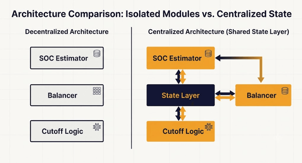
Most BMS designs treat SOC estimation, cell balancing, and cutoff protection as three separate modules. Each one runs its own logic. Each one reads its own inputs. This works, but it leaves value on the table. An integrated BMS control architecture ties these three functions together instead. They share one live state, not three separate guesses. This guide covers what that shared state looks like, and why it matters for LFP. New to BMS fundamentals first? Our BMS explained guide covers the basics before returning here.
| ⚡ Quick Answer An integrated BMS control architecture means the SOC estimator, the cell balancer, and the cutoff logic all read from one shared, current view of each cell’s voltage, resistance, and temperature. Without this link, each subsystem can act on a slightly different picture of the pack, and small disagreements between them compound into real errors. |
Why Three Separate Modules Create Hidden Errors
This challenge is related to a broader question in battery-pack monitoring: whether separately-run, local estimators can be trusted to agree with a fully centralized view. Research on distributed Kalman filtering across battery pack cells explores this tradeoff for thermal estimation specifically, finding that distributed approaches can track a centralized estimate closely when properly designed — the same coordination problem this article addresses for SOC, balancing, and cutoff logic. A BMS built as three separate modules seems simpler at first. But each module often keeps its own internal estimate of pack state. The estimator has its own SOC value. The balancer has its own view of cell voltage spread. The cutoff logic has its own read on present resistance. These three views should agree. In practice, small timing gaps and separate filtering choices let them drift apart, even by a small amount.
A Concrete Example of the Problem
Picture a cell under a sudden high-current pulse. The estimator’s filter may lag the true voltage sag. The lag can run a few hundred milliseconds. The cutoff logic reads raw current and voltage directly. So it reacts faster. It might trip a cutoff. The estimator’s own SOC value says this should not happen yet. Without shared state, this looks like a bug. An integrated BMS control architecture fixes it. Both systems read the same current-corrected voltage, in real time. The mismatch does not occur.
What Shared State Means for an Integrated BMS Control Architecture
An integrated BMS control architecture is not one giant algorithm. It is a shared data layer that each function reads from and writes to. At minimum, this layer holds present cell voltage, present current, present temperature, the estimator’s current SOC output, and the present DCIR value drawn from the resistance lookup table. Every subsystem calculates from this same set of numbers, on the same update cycle.
Update Timing Matters as Much as the Data Itself
Sharing the right data at the wrong update rate still causes disagreement. The cutoff logic needs the fastest update path. A hard voltage limit can be reached in milliseconds, under a current spike. The SOC estimator can run on a slower cycle instead. Its correction task is inherently smoother. Design the shared state layer so each subsystem pulls at its own needed rate. Do not force one single rate onto all three.
How Subsystems Interact in an Integrated BMS Control Architecture
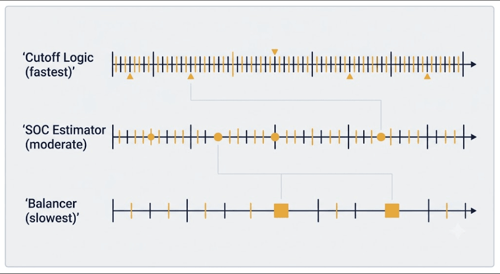
With shared state in place, the three subsystems can do more than avoid disagreement. They can actively support one another. The estimator’s SOC output can flag the balancer toward cells worth watching. The balancer’s voltage-spread data can flag the estimator when a cell’s behavior looks abnormal, rather than just imbalanced. The cutoff logic’s live DCIR reading, drawn from the same lookup table an EKF SOC estimation design pulls its resistance model from, keeps both systems working from one resistance picture instead of two.
Flagging Faults Instead of Silently Adapting
A well-built integrated BMS control architecture also creates a natural place to catch faults. If the shared DCIR reading from one cell departs sharply from its neighbors, and that departure does not track with the pack’s overall temperature or aging trend, the architecture can flag it as a possible fault, tied to the same in-service cell imbalance and DCIR drift patterns covered elsewhere in this series. This is far harder to catch when each subsystem only sees its own narrow slice of the picture.
Implementing an Integrated BMS Control Architecture Without a Full Redesign
For how centralized, modular, and wireless BMS topologies differ in where this shared layer can physically live, see our BMS architecture guide. Building an integrated BMS control architecture does not usually require new sensors. Most BMS hardware already measures voltage, current, and temperature at a resolution that supports this. The work is mostly in firmware: defining the shared data structure, setting update rates per subsystem, and routing each function’s calculation through the shared layer instead of an isolated local copy.
A Practical Migration Path
Start with the two subsystems most likely to disagree today: the SOC estimator and the cutoff logic, since both read current and voltage directly and both act on threshold logic. Confirm they draw from one shared, current-corrected voltage value before adding the balancer into the same layer. This staged approach limits the scope of any one firmware change and makes each step easier to validate on its own.
Key Takeaways
Three separate BMS modules can quietly disagree, even when each one works correctly on its own. An integrated BMS control architecture fixes this with one shared data layer for voltage, current, temperature, SOC, and DCIR, read by all three subsystems. Update timing matters as much as the shared data itself; each subsystem should pull at the rate its own task needs. Shared state also creates a natural place to flag developing faults, since a real fault shows up as one cell’s data breaking pattern against the rest of the shared picture.
Frequently Asked Questions
Does an integrated BMS control architecture need new hardware?
Usually not. Most BMS hardware already measures voltage, current, and temperature at a fine enough resolution. The work is mainly firmware: building a shared data layer and routing each subsystem’s calculation through it.
Which two subsystems should be integrated first?
Start with the SOC estimator and the cutoff logic. Both read current and voltage directly, and mismatches between them are the most likely to show up as a false or late cutoff trip.
How does an integrated BMS control architecture help catch developing faults?
When every subsystem shares one live view of each cell, a real fault shows up as that cell’s data breaking pattern against its neighbors and against the pack’s overall trend, rather than being missed by a subsystem that only sees its own narrow slice of the picture.
Further Reading
BMS Architecture Explained: Centralised vs Modular vs Wireless
Battery Management System (BMS) Explained
BMS SOC Estimation Methods Explained
EKF SOC Estimation Design for LFP BESS









Trackbacks & Pingbacks
[…] our integrated BMS control architecture guide for how a shared-state design removes the guesswork each layer would otherwise carry on its […]
[…] control layer, avoids that trade-off. It’s the same shared-state pattern covered in our integrated BMS control architecture guide — mixed-age string design is one more reason that architecture earns its […]
[…] Integrated BMS Control Architecture […]
Leave a Reply
Want to join the discussion?Feel free to contribute!