
Why Deep Discharge and High C-Rate Stress LFP Cells: Particle Cracking and Concentration Polarization
Every LFP datasheet gives a depth of discharge number and a C-rate limit, the two levers behind DoD C-rate stress. Still, fewer explain what actually happens inside the cell when you push past them. DoD C-rate stress is the physical reality behind those two numbers. It is not an arbitrary warranty term. Instead, it is real mechanical and electrochemical strain on the electrode itself.
So this guide skips the buyer’s-guide framing. It explains the mechanism instead. First, it covers what happens to an electrode particle during a single lithium insertion and extraction cycle. Then it covers why deep discharge makes that worse. Then it covers why high C-rate makes it worse again, through a different pathway. Finally, it covers what happens when both combine at once.
| Quick Answer DoD C-rate stress is the mechanical and electrochemical strain that deep cycling and fast charging place on an LFP cell’s electrode particles. Deep discharge causes larger volume changes inside each particle, leading to particle cracking over time. High C-rate creates steep lithium concentration gradients. This adds mechanical stress. It also raises the risk of local lithium plating, even when the average current looks safe. |
DoD C-Rate Stress: What Happens Inside a Particle
Every time an LFP cell charges or discharges, lithium ions move in and out of the electrode particles. But that movement is not free. It changes the particle’s volume every time.
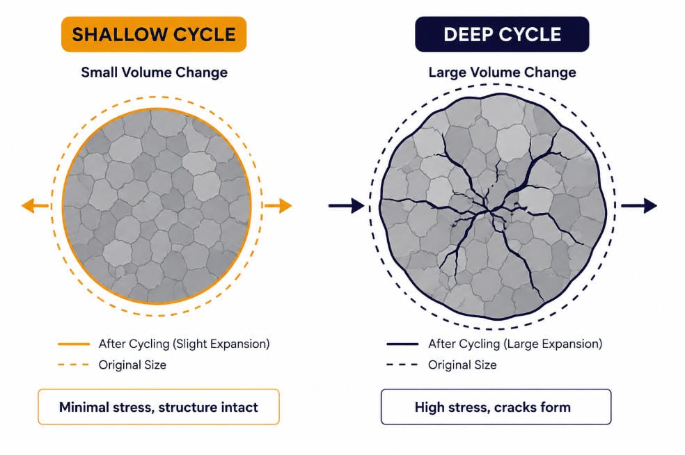
LFP and its delithiated counterpart, FePO4, differ in volume by about 6.8%. So every full cycle pushes a particle through that volume change and back. This is not a smooth, uniform process either. Lithium moves through the particle unevenly, especially at speed, creating internal concentration gradients between lithium-rich and lithium-poor regions. So those gradients generate real mechanical stress inside the particle.
Researchers have a specific name for the resulting damage in LFP cells: electrochemical milling. This is the process where LFP particles crack and crumble. Repeated volume change causes the mechanical stress behind it. First, early in a cell’s life, this cracking is not entirely bad. It exposes fresh surface area. It can even help ion transport briefly. But over time, continued milling causes particles to detach from the conductive carbon network entirely. So that detached material becomes electrically isolated. It stops contributing capacity for good.
DoD C-Rate Stress: Why Deep Discharge Makes It Worse
Depth of discharge is not just a capacity number. Instead, it is a direct measure of how far each particle gets pushed through its volume-change cycle, every single time.
Take a shallow cycle, say 20% to 80% state of charge. It keeps particles moving through a smaller slice of that range. A deep cycle from close to 0% up to 100% is different. It pushes particles through nearly the entire range, every time. So recent research using direct imaging of individual LFP particles confirms this link concretely. Operando imaging studies show something specific. Lithium concentration distribution and the resulting internal stress fields are directly tied to how far a particle gets cycled. So deeper excursions create larger, more damaging stress fields.
So this is exactly why partial state-of-charge cycling extends cycle life so reliably. It is not a soft recommendation. Instead, it reflects less particle-level strain, cycle after cycle. So shallow cycling protects the electrode structure directly. It works at the mechanical level, not just at the voltage level.
Why High C-Rate Makes This Worse Again
C-rate adds a second stress pathway on top of depth of discharge. It works through a different mechanism.
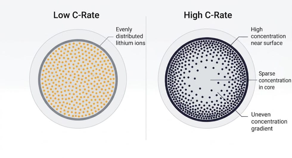
At low C-rates, lithium has time to distribute fairly evenly through a particle as it moves in or out. But at high C-rates, it does not. Instead, ions pile up near the particle surface faster than they can diffuse toward the center. This creates a steep internal concentration gradient, even if the overall depth of discharge stays the same. So that steep gradient adds mechanical stress independent of how deep the cycle actually goes. Research modeling particle-level behavior confirms this directly. Cracking occurs more severely at higher currents. It worsens further with larger particle sizes.
So high C-rate creates a second, separate risk beyond mechanical stress. At the electrode surface, fast charging causes concentration polarization. That is a buildup of lithium ions that outpaces how quickly the surrounding electrolyte and electrode structure can absorb them. This local buildup can push the anode’s surface potential down toward the plating threshold. That can happen even when the average current across the whole cell looks perfectly safe on paper. For the full mechanism behind that plating threshold, see our guide on SEI Layer Growth and Lithium Plating in LFP Cells.
DoD C-Rate Stress: When Both Combine
DoD C-rate stress is worst when both factors stack together, and that combination is common in real BESS operation, not just a lab edge case.
A cell cycled deep and fast gets hit twice. It experiences the largest volume-change stress from depth of discharge. At the same time, it faces the steepest concentration gradients from high current. But these two stress sources do not simply add. The uneven lithium distribution from fast charging concentrates strain in specific regions of the particle. Those same regions then get pushed through the largest volume swings from the deep discharge on top. So that combination accelerates electrochemical milling faster than either factor alone would predict.
This is one reason cycle life ratings drop sharply when both depth of discharge and C-rate increase together. The drop is not simply additive. A cell rated for thousands of cycles at shallow depth and moderate current can lose a large fraction of that rating. This happens when it gets pushed to both extremes at once.
How This Connects to the Bigger Degradation Picture
DoD C-rate stress is one of the concrete mechanisms behind cycle aging specifically, as distinct from the calendar aging that happens purely with time.
The mechanical stress covered here scales with cycle count and depth. It does not scale with elapsed time at rest. So that is exactly the signature of cycle aging. For the full breakdown of how cycle aging and calendar aging interact, and how operators separate the two using the Equivalent Full Cycle method, see our guide on Calendar Aging vs Cycle Aging in LFP Batteries. The particle cracking mechanism explained here is a major reason why that range exists. Cycling conditions like depth of discharge and C-rate explain a wide spread in EFC-based end-of-life ratings.
Particle cracking also creates fresh surface area. That fresh surface needs new SEI to cover it. So DoD C-rate stress connects directly to SEI growth too. Every cracking event is not an isolated capacity loss. Instead, it triggers a small amount of additional SEI-driven capacity loss on top.
Why This Matters More for Some BESS Applications Than Others
DoD C-rate stress does not hit every BESS application equally. Usage pattern determines how much this mechanism matters for a given system.
Take a solar-paired storage system that charges and discharges once a day at a moderate rate. It sits at the low-stress end of this spectrum. It rarely pushes into deep discharge territory, and its C-rate stays modest across a typical cycle. A frequency-regulation asset looks very different. It cycles constantly, often at higher C-rates, though usually across a shallower depth of discharge window. So the DoD C-rate stress mix differs by application, even before considering total cycle count.
The worst-case combination shows up in applications that need both deep discharge and high C-rate at once. Backup power systems sized tightly against peak demand are a good example. Those systems have less room to avoid the combined stress case covered above. Both extremes may be operationally necessary rather than optional. Understanding this mechanism helps explain something useful. Identical nameplate systems in different applications can show meaningfully different real-world cycle life, even under the same warranty terms.
What This Means in Practice
None of this changes the practical guidance much. Still, it explains why that guidance exists.
Keeping cycles shallow, inside a window like 20% to 80%, is not an arbitrary rule. Instead, it directly limits how far electrode particles travel through their volume-change cycle. Keeping C-rate moderate limits how steep the internal concentration gradients get, on top of that. For the buyer-facing numbers behind these two levers, see our guides on BESS C-Rate Explained and 20/80 Rule for Batteries. Both include specific cycle-life figures at different depth of discharge and C-rate combinations. Both cover the practical operating windows this guide explains the mechanism behind.
DoD C-Rate Stress: Quick Reference
| Factor | What Happens at the Particle Level |
| Deep discharge | Larger volume-change swing per cycle, more particle cracking over time |
| High C-rate | Steep lithium concentration gradients, added mechanical stress |
| High C-rate (secondary effect) | Local concentration polarization can push toward plating risk |
| Combined deep + fast cycling | Stress sources compound rather than simply add |
| Resulting damage | Electrochemical milling, particle detachment, exposed surface for new SEI growth |
| Practical lever | Shallow SOC window and moderate C-rate both reduce particle-level strain directly |
Frequently Asked Questions
In DoD C-rate stress, is particle cracking the same thing as SEI growth?
No, but the two are connected. Particle cracking is a mechanical process driven by volume change and internal stress. It exposes fresh surface area, which then triggers new SEI growth on that surface. One mechanical event causes a follow-on chemical one.
Under DoD C-rate stress, does shallow cycling eliminate particle cracking entirely?
No. Some degree of volume change and internal stress happens on every cycle, even a shallow one. Shallow cycling reduces the stress substantially rather than eliminating it.
Why does high C-rate matter even if depth of discharge stays the same?
C-rate affects how evenly lithium distributes inside a particle during a given cycle. This holds independent of how deep that cycle goes. Faster currents create steeper internal concentration gradients, adding stress on top of whatever depth of discharge is in use.
Can this mechanism cause sudden capacity loss, or is it always gradual?
It is usually gradual, showing up as steady capacity fade. But accumulated particle cracking and detachment can contribute to an accelerated fade phase later in a cell’s life. This is sometimes described as a knee point in the capacity curve.
Further Reading
Battery Degradation in BESS: Causes, Mechanisms & Mitigation
SEI Layer Growth and Lithium Plating in LFP Cells
Calendar Aging vs Cycle Aging in LFP Batteries







Trackbacks & Pingbacks
[…] For the full breakdown of how these variables interact at the particle level, read our guide on Why Deep Discharge and High C-Rate Stress LFP Cells. […]
[…] Repeated deep discharges add a different kind of stress, too. On the next charge, lithium ions must fully repopulate the lattice. This places real mechanical strain on the cathode. This places real mechanical strain on the cathode. For the full mechanism behind that strain — including why deep cycling causes particle cracking over time — see our guide on Why Deep Discharge and High C-Rate Stress LFP Cells. […]
Leave a Reply
Want to join the discussion?Feel free to contribute!