

BESS Grid Connection Studies: Load Flow, Short-Circuit, Harmonics, RMS and EMT Modelling
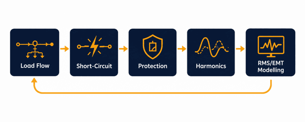
BESS grid connection studies are the engineering checks a network operator runs before it approves a battery storage project. Each study asks the same underlying question: can this plant connect and operate without exceeding voltage, thermal, fault-level, protection, or power-quality limits at the connection point? This guide covers the core BESS grid connection studies: load flow, short-circuit, protection coordination, harmonics, and RMS/EMT dynamic modelling.
Last reviewed: September 2026. Study requirements vary by network operator, project design, grid strength, and applicable grid code.
This guide walks through:
- What each of the core study types actually checks
- Why RMS and EMT modelling are different tools, not two names for the same thing
- Where these studies sit inside the wider interconnection timeline
- What a BESS developer needs to supply before a network operator can run them
- Common reasons a study package gets rejected or delayed
Quick Answer
BESS grid connection studies are the technical checks a network operator runs before interconnection: load flow, short-circuit, harmonics, and RMS/EMT dynamic modelling. Together, they confirm a battery project can connect safely, without degrading voltage, fault protection, or power quality on the connecting network.
BESS Grid Connection Studies Checklist
Before locking the BESS configuration or signing a PCS supply agreement, work through this checklist.
- Identify the likely point of connection, voltage level, and export/import capacity
- Obtain the network operator’s formal study scope, model format, and submission timeline
- Confirm whether the plant must operate grid-following, grid-forming, or both
- Obtain validated RMS models, and EMT models where required, for the PCS and plant controller
- Confirm the model’s operating range, control modes, fault-response logic, and firmware version
- Screen local grid strength, nearby inverter-based resources, and background harmonic levels early
- Reserve schedule time for model review, study reruns, and compliance testing
- Carry a contingency for mitigation measures such as filtering, a revised export limit, or grid-forming controls
What Are BESS Grid Connection Studies?
BESS grid connection studies answer one question. Can this project connect here safely? The network operator studies the plant at its point of interconnection (POI), sometimes called the point of common coupling (PCC). It then compares the results against the planning limits already set for that part of the grid.
Specifically, study scope depends on three main factors: project size, connection voltage, and how electrically “stiff” or “weak” the network already is. For instance, a small distribution-connected project may only need a load flow and a short-circuit study. A large transmission-connected BESS at a weak point of connection may require a broader package, including load flow, short-circuit, protection, harmonic, RMS dynamic, and potentially EMT studies. Our guide to the BESS interconnection process covers where this study stage sits inside the wider application-to-commissioning workflow.
Why BESS Grid Connection Studies Don’t Follow One Fixed Order
Network operators often organise BESS grid connection studies in phases, but not always in a strict, one-way order. Early load flow and short-circuit work usually establishes basic connection feasibility first. Protection, harmonics, RMS, and EMT studies can run in parallel, or get repeated, as the selected PCS, transformer, plant controller, and operating limits become clearer. Treat the study package as an iterative engineering process, not a single pass through a checklist.
Load Flow: The First of the BESS Grid Connection Studies
A load flow study is also called a power flow study. It models the network in its normal, steady-state condition, with the new BESS connected. The question is simple. Will voltages and equipment loading stay inside acceptable limits once this plant is added?
In addition, the study represents the BESS plant in full detail rather than as one generic source. A proper power flow model includes the generator tie line, the main step-up transformer, the collector system, and the plant’s reactive power range at every output level, from full charge to full discharge. A BESS is a four-quadrant device, so the study checks both directions of power flow. Therefore, it does not simply evaluate export power.
What a Load Flow Study Looks For
- Thermal loading on lines, cables, and transformers under peak import and export
- Voltage rise and voltage drop across the connection, under different dispatch scenarios
- Whether existing voltage-regulation equipment, like tap changers, still works correctly
- Reverse power flow conditions that did not exist before the BESS connected
- The reactive power range the plant must hold to keep voltage inside its schedule
In practice, a voltage or thermal violation usually leads to revised operating limits, network reinforcement, or design changes that get assessed in a further study iteration, rather than an outright rejection. This is a normal, expected part of BESS grid connection studies, not a sign the project has failed.
Short-Circuit Studies for BESS Grid Connection
A short-circuit study is also called a fault-level study. It calculates how much current would flow during a fault, at different points on the network, both with and without the BESS connected. The network operator uses this to confirm existing switchgear, relays, and conductors can still safely handle a fault once the new plant joins the system.
BESS fault behaviour differs from a conventional generator’s fault behaviour in a real way. A synchronous machine’s fault current is limited mainly by its own impedance, and it can spike to several times rated current for a brief period. A BESS PCS instead limits fault current through its own control and protection logic. As a result, the magnitude, sequence components, duration, and active-versus-reactive current priority can all vary by inverter design, grid code, control mode, fault type, and voltage conditions. This distinction matters for protection coordination. Protection designed around conventional-generator assumptions may lose sensitivity, selectivity, or coordination once the connected resource has inverter-limited fault-current behaviour.
Maximum and Minimum Fault Levels in BESS Grid Connection Studies
A thorough short-circuit study calculates two separate cases, not one. The maximum fault level, using the highest credible fault current, confirms equipment ratings are not exceeded. The minimum fault level, using the lowest credible fault current, confirms protection relays still see enough current to clear a fault reliably. One international standard covers the underlying AC-side calculation method in detail: IEC 60909, developed for AC short-circuit currents generally and increasingly applied to BESS/PCS fault contribution. A separate standard, IEC 61660, covers fault calculations in station DC and auxiliary DC systems. That’s relevant to a BESS’s own DC-side protection design, but it is separate from the AC grid-fault analysis that normally forms part of a network operator’s interconnection study. The same IEC technical committee developed both.
Protection Coordination in BESS Grid Connection Studies
Protection coordination is often scoped as its own study, separate from the short-circuit calculation itself. The short-circuit study sets the fault-current numbers. Meanwhile, the protection study decides what the relays actually do with those numbers.
The network operator checks that protection isolates a fault selectively, tripping the minimum necessary equipment while maintaining coordinated backup protection where required. Protection must also stay secure during external events, riding through rather than clearing. This gets more involved with a BESS on the feeder. Its current contribution is shaped by inverter control logic, not fixed machine impedance.
What a Protection Study Checks
- Relay grading and trip-curve settings across the feeder, with the BESS included
- Whether protection stays selective, so only the closest device clears an internal fault
- Anti-islanding detection and response
- Current-transformer and voltage-transformer sizing against the new fault-current profile
- Coordination margins between the BESS’s own protection and the network operator’s relays
A February 2026 National Energy System Operator (NESO) guidance document on RMS and EMT model requirements identifies overvoltage and undervoltage protection, over- and under-frequency protection, and DC bus voltage and current protection as functions that should be represented where relevant to the inverter-based resource, modelled for both balanced and unbalanced fault conditions. That level of protection detail needs to reach the study, not just sit in the PCS vendor’s own product documentation.
Harmonics: The Power-Quality Piece of BESS Grid Connection Studies
A harmonics study checks waveform quality at the connection point, not just its magnitude. A battery inverter switches at high frequency to convert DC to AC. That switching process injects some waveform distortion back into the grid, alongside its intended fundamental-frequency output.
Two related metrics matter here. Voltage THD (total harmonic distortion) expresses the RMS value of harmonic voltage components relative to the fundamental voltage. Current TDD (total demand distortion) expresses RMS harmonic current relative to the maximum demand load current, rather than the instantaneous fundamental current, which keeps the limit meaningful at light-load conditions too. Both voltage and current distortion can technically be expressed as THD, but in the US, IEEE 519 commonly uses TDD specifically for evaluating current distortion at the point of common coupling. Network operators may also assess individual harmonic components, interharmonics, resonance, and planning levels beyond these two headline figures. Internationally, IEC/TR 61000-3-6 gives a comparable framework for assessing harmonic emission limits when connecting a distorting installation, inverter-based generation included, to medium, high, and extra-high voltage systems.
Why Inverter-Based Resources Change the Harmonics Picture
A single small inverter rarely causes a measurable problem on its own. However, a utility-scale BESS plant is different. So is a feeder where BESS and solar PV share the same connection point. Harmonic currents from multiple sources can add together at certain frequencies, rather than simply cancel out. The available fault current at the connection point also affects how much voltage distortion a given harmonic current actually produces, which is why harmonics work is closely tied to the short-circuit study rather than assessed in isolation. A weaker fault level turns the same harmonic current into a larger voltage distortion.
RMS and EMT Dynamic Modelling for BESS Grid Connection Studies
RMS and EMT are the two simulation domains used to study how a BESS plant behaves during a disturbance, not just at steady state. They answer different questions, at different levels of detail. A network operator usually specifies which one it needs based on how electrically weak the connection point already is.
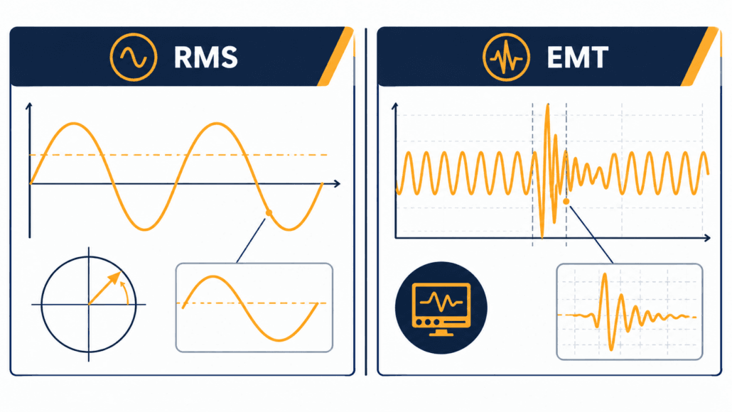
First, RMS modelling stands for root-mean-square, or phasor-domain, simulation. It represents the network using simplified fundamental-frequency phasors. It tracks how power, voltage, and frequency evolve over seconds to minutes. So RMS is efficient enough to study a large interconnected network. It is the standard tool for frequency response, voltage stability, and wide-area planning work.
Conversely, EMT modelling stands for electromagnetic transient simulation. It represents the actual instantaneous waveform, not a simplified phasor. It captures behaviour on the scale of microseconds to milliseconds. Even so, EMT is far more demanding to compute, which limits it to a smaller network area. It is generally the preferred domain for capturing fast inverter control-loop interactions, detailed unbalanced-fault behaviour, switching transients, and other sub-cycle dynamics that a simplified RMS model may not capture adequately.
When EMT Modelling Becomes Necessary
A 2023 NERC reliability guideline on BESS and hybrid plant modelling identifies low short-circuit strength, interaction risk among multiple inverter-based resources, and grid-forming control as important situations where detailed EMT assessment may be appropriate. The final requirement stays project- and network-operator-specific. Still, RMS models stay adequate for most standard planning and screening work. Even so, network operators increasingly ask for both. RMS handles the broad system-wide screening. EMT handles the specific, electrically sensitive area near the new plant.
For the country-specific grid-code obligations these studies are designed to demonstrate, see our BESS Grid Codes and Compliance guide.
RMS vs EMT at a Glance
| Factor | RMS (Phasor-Domain) | EMT (Electromagnetic Transient) |
| Time scale | Seconds to minutes | Microseconds to milliseconds |
| Represents | Simplified fundamental-frequency phasor | Actual instantaneous waveform |
| Typical use | Frequency response, voltage stability, wide-area planning | Weak-grid behaviour, control interactions, protection response |
| Network size | Large, interconnected systems | Smaller, localized network area |
| Computational cost | Lower | Considerably higher |
| Model source | Vendor-supplied standardised dynamic model | Vendor-supplied detailed EMT model |
System Strength and Weak-Grid Considerations
System strength describes how firmly the local network holds its voltage and frequency steady when a disturbance hits. A weak point of connection has relatively high impedance. That makes it more sensitive to fast inverter-control action, not less.
Indeed, a BESS can genuinely help a weak grid, especially with a well-designed voltage-control or grid-forming PCS. But connecting at a weak point still raises real risks. The study package needs to catch control-loop instability in grid-following inverters, conflicts between current limits and voltage support, harmonic amplification, and slower fault ride-through than a stronger point would show.
Grid-Forming Controls Don’t Automatically Fix a Weak Grid
Grid-forming capability has to be assessed against three things: the specific operating mode the network operator requires, the protection design, and how the plant interacts with other inverter-based resources nearby. It is one mitigation option among several, not an automatic pass. Our Australia BESS grid connection guide covers how one network operator assesses system strength and grid-forming capability in practice, including where AEMO’s own guidance applies.
How BESS Grid Connection Studies Fit Into the Interconnection Timeline
These study types do not run on their own. They sit inside one defined stage of the wider interconnection process. That stage generally follows the initial application and feasibility screening, but comes before a formal connection agreement. Our BESS interconnection process guide covers this full sequence step by step. The country guides for Australia, the UK, and Europe each show how local network operators schedule this stage in practice.
What a Developer Must Supply for BESS Grid Connection Studies
The network operator cannot run a meaningful study without accurate models from the project side. A model that does not match the as-built equipment is one of the most common reasons a study result later fails to match real commissioning-test behaviour. A typical model-deliverable package includes:
- PCS RMS model in the network operator’s required format
- EMT model, where requested or reasonably anticipated
- Plant-controller model and parameter file
- Inverter control-mode descriptions and operating limits
- Transformer vector group, impedance, tap range, and grounding data
- Cable and collector-system parameters
- Protection single-line diagram and proposed relay settings
- Reactive-power capability curve
- Harmonic emission spectrum or equivalent frequency-domain data
- Firmware, model, and controller version numbers
- Model validation report and revision history
Common Pitfalls in BESS Grid Connection Studies
Most delays in a BESS grid-study package trace back to a small set of recurring issues. In fact, few come from a genuinely hard technical problem.
Common Study Failures and How to Avoid Them
| Failure | Why It Happens | How to Prevent It |
| Studies start with only generic inverter data | The selected PCS or control configuration isn’t final yet | Use generic data for early screening only; replace it with validated project-specific models before final submission |
| Charging mode gets treated as secondary | Teams model export in detail but skim over maximum import and reactive-only cases | Include charging, discharging, standby, and reactive-only cases from the start |
| Co-located equipment gets left out | Nearby solar, capacitor banks, and cables all shift the dynamic and harmonic picture | Model the full plant and any electrically relevant equipment nearby |
| A model is submitted unvalidated | The network operator can’t reproduce the plant’s expected behaviour | Require validation evidence and parameter traceability from the PCS supplier |
| Late firmware changes go unreported | The installed controls no longer match the approved model | Use formal change control, and resubmit for study when material settings change |
How Study Results Affect BESS Cost and Revenue
Grid connection studies aren’t just a technical hurdle; instead, their results feed straight into the project’s business case. A study can change several things at once. The substation and protection scope. The PCS rating actually needed. Whether harmonic filtering or extra reactive-power equipment gets added. The final export or import capacity the plant is allowed.
A project designed around a 100 MW PCS might come out of studies with only 80 MW of firm export capacity. Or it might carry a reactive-power reservation that reduces available active power at certain voltage conditions. Each of those changes affects CAPEX, usable revenue capacity, and lifetime project economics. So study results should inform the financial model before procurement is finalised, not after.
For the cost and revenue side of that picture, see Sunlith’s guides to BESS CAPEX calculation, BESS OPEX and operating cost modelling, and BESS revenue streams and value stacking.
Comparing the Core BESS Grid Connection Studies
| Study | Domain | Core Question | Typical Trigger |
| Load flow | Steady state | Do voltage and thermal limits hold with the plant connected? | Most grid-connected projects |
| Short-circuit | Fault condition | Does fault current stay within equipment and protection limits? | Common for projects requiring detailed technical review |
| Protection coordination | Fault response | Does protection stay selective and secure with the BESS added? | Where protection settings, fault duty, or anti-islanding could be affected |
| Harmonics | Waveform quality | Does distortion stay within planning levels at the connection point? | Common for inverter-based systems, where required by the operator or power-quality standard |
| RMS/EMT dynamic | Transient/dynamic | Does the plant stay stable through disturbances and control interactions? | More likely for large, weak-grid, grid-forming, or transmission-connected projects |
Frequently Asked Questions
Common questions readers ask about BESS grid connection studies, answered directly.
Does every BESS project need all of these grid connection studies?
Not always. Smaller distribution-connected projects on a strong network often only need load flow, short-circuit, and protection coordination studies. Harmonics and dynamic RMS/EMT studies become more likely as project size grows, as the connection point gets weaker, or as the project uses grid-forming controls. Confirm the required scope with the relevant network operator.
Who actually performs BESS grid connection studies?
The network operator, or transmission owner, typically runs the studies. It uses models the developer’s equipment vendors and system integrator supply. Some markets let a developer commission an independent, accredited study provider for part of the work, subject to the operator’s review.
What’s the real difference between RMS and EMT modelling?
RMS modelling represents slower power-system dynamics using simplified phasors. In contrast, EMT modelling represents the actual instantaneous waveform, capturing much faster behaviour down to microseconds. EMT suits weak-grid and control-interaction studies that RMS cannot see in enough detail.
Why does a BESS need its own short-circuit study, instead of using generic generator data?
A battery inverter’s fault current is limited by its control system, not by machine impedance, so it behaves differently from a synchronous generator during a fault. Reusing generic synchronous-generator assumptions for a BESS can misrepresent both the maximum and minimum fault-current cases that protection settings depend on.
How long does a full grid connection study package take?
Timelines vary by market, network operator workload, and study complexity. They can range from a few weeks for a simple load flow and short-circuit package, to many months where full RMS and EMT modelling is required. Treat any timeline as a planning estimate, and confirm current queue times with the relevant network operator.
What happens if a project fails a grid connection study?
A failed result rarely ends the project outright. So the network operator usually proposes a fix instead, such as a lower export limit, added reactive power support, network reinforcement, or a different control-mode requirement. The project is then re-studied against the revised assumptions. Rejection outright is uncommon in real BESS grid connection studies.
Do harmonics studies apply differently to a BESS than to solar PV?
The underlying inverter switching behaviour is similar. But a BESS charges and discharges across a four-quadrant range, so its harmonic contribution needs checking across a wider set of operating points than a generation-only solar PV plant, which only ever exports.
Does a grid-forming BESS need a different study approach?
Often, yes. Grid-forming BESS projects are more likely to require detailed EMT assessment, because control-loop, current-limit, and fault-response behaviour can matter a great deal in weak-grid conditions. RMS modelling may still cover the broader system studies, but the network operator may separately require EMT evidence for the local interaction assessment.
Can a firmware update trigger a new grid connection study?
Yes. If a firmware change alters protection behaviour, current limits, grid-forming logic, fault ride-through, or reactive-power control, the network operator may require a fresh assessment or an updated model. Treat firmware updates on commissioned equipment as controlled engineering changes, not routine maintenance.
Glossary
More Sunlith Energy definitions for terms used throughout this BESS grid connection studies guide.
Study and Network Terms
Load flow (power flow) study — A steady-state check of voltage and equipment loading across the network, with a new plant connected.
Short-circuit (fault-level) study — A check of fault current magnitude at points across the network, used to confirm equipment and protection ratings.
POI (point of interconnection) — The physical point where a generating plant connects to the wider network.
PCC (point of common coupling) — The point on the network, often the same as the POI, where harmonic and power-quality limits get assessed.
System strength — How firmly a local network holds voltage and frequency steady when a disturbance occurs; a low-strength, or “weak,” connection point is more sensitive to fast inverter-control action.
Modelling and Power-Quality Terms
RMS modelling — Phasor-domain simulation used to study slower power-system dynamics, over seconds to minutes.
EMT modelling — Electromagnetic transient simulation used to study fast, instantaneous waveform behaviour.
THD (total harmonic distortion) — The RMS value of harmonic voltage (or current) components relative to the fundamental. Commonly used for voltage distortion at the connection point.
TDD (total demand distortion) — RMS harmonic current relative to the maximum demand load current, not the instantaneous fundamental current. IEEE 519 commonly uses this for current distortion.
Disclaimer
Important: This guide is general technical information, not project-specific engineering advice. Study requirements, thresholds, and timelines vary by network operator, connection voltage, project size, and jurisdiction. Confirm the required study scope and current standards with the relevant network operator, and a qualified electrical or grid-connection engineer, before relying on any figure here for a real project.
Further Reading
More Sunlith Energy guides on BESS interconnection, grid codes, and short-circuit standards.
- Follow the full BESS interconnection process (BESS Interconnection Process: From Application to Commercial Operation)
- Review BESS grid-code requirements by country (BESS Grid Codes and Compliance)
- Learn AC-side fault-current calculation under IEC 60909 (IEC 60909 Explained: AC Short-Circuit Currents for BESS)
- See DC auxiliary-system fault-current calculation under IEC 61660 (IEC 61660 Explained: Calculating DC Short-Circuit Currents)
- Explore the PCS hardware behind fault ride-through (Fault Ride-Through Features: PCS Hardware and Control Functions)
- Review LVRT and HVRT voltage ride-through requirements (LVRT and HVRT: Voltage Ride-Through Requirements)
- Compare Australia’s AEMO/TNSP/DNSP connection process (Australia BESS Grid Connection)
- Compare the UK’s NESO/DNO connection process (UK BESS Grid Connection)
- Compare the EU’s country-by-country connection process (Europe BESS Grid Connection)
- See the BESS CAPEX calculation methodology (BESS CAPEX Calculation)
- See the BESS OPEX and operating cost model (BESS OPEX and Operating Cost Model)
- See how BESS revenue streams stack (BESS Revenue Streams and Value Stacking)
Sources and Technical References
Primary and external sources cited in this article.
1. NERC, “Reliability Guideline: Performance, Modeling, and Simulations of BPS-Connected Battery Energy Storage Systems and Hybrid Power Plants,” June 2023.
2. IEEE Std 519-2022, “IEEE Recommended Practice and Requirements for Harmonic Control in Electric Power Systems.”
4. National Energy System Operator (NESO), “Frequently Asked Questions on Root Mean Square (RMS) and ElectroMagnetic Transient (EMT) Model Requirements,” February 2026.