

Active Balancing Hardware Topologies Compared: Transformer, Switched-Capacitor, and DC-DC Converter Circuits
Active balancing hardware topologies solve a problem passive balancing can’t. They move real energy between mismatched cells instead of burning it off as heat.
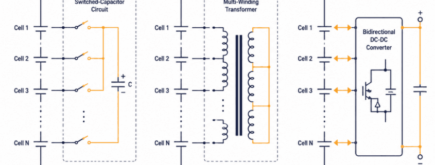
Three main hardware options compete for that job: switched-capacitor circuits, transformer-based circuits, and DC-DC converter circuits.
Each moves charge differently. Each also carries its own cost, speed, and reliability trade-offs.
This guide breaks down how each topology works. It also covers where each one fits in a utility-scale LFP rack, and how to choose between them.
| Quick Answer Switched-capacitor circuits are cheap but slow, since they only move charge between neighboring cells. Transformer-based circuits balance faster but cost more per rack. DC-DC converter circuits offer the best mix of speed and any-cell-to-any-cell transfer, which is why most utility-scale LFP systems use them. |
What Active Balancing Hardware Topologies Solve That Passive Balancing Can’t
Passive balancing bleeds off the highest-voltage cell’s excess energy through a resistor. That energy is gone for good.
Active balancing hardware topologies capture it instead. They then route that same energy into the weakest cell in the string.
The In-Service Cell Imbalance guide covers when passive balancing is good enough, and when active balancing earns its extra cost.
This guide picks up from there. It stays inside the active-balancing box itself.
Grid-services duty cycles spend most of their life in a narrow SOC band. That’s where the difference compounds fastest.
A few recovered percentage points per cycle add up over a project’s life. The pillar article covers that revenue angle in more depth.
Switched-Capacitor Circuits: The Simplest Balancing Topology
How Switched-Capacitor Balancing Moves Charge
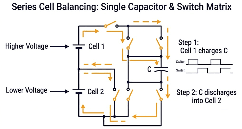
A single capacitor connects across two neighboring cells at a time. Then a switch matrix decides which pair.
The capacitor charges from the higher-voltage cell. It then discharges into the lower-voltage cell next to it.
Multi-switched-capacitor designs use one capacitor per cell pair, not a shared one. That parallel setup balances every neighbor pair at once, so it works faster.
Where Switched-Capacitor Circuits Fit in a BESS
Switched-capacitor circuits need almost no control logic, so they end up cheap and reliable.
The trade-off is reach. Energy can only hop between adjacent cells.
So an imbalance between cell one and cell fifty takes many hops to fix. Also, each hop adds time and loses a little energy.
That slow, local-only transfer path explains where switched-capacitor circuits show up. They suit smaller packs, not full utility racks with two hundred or more cells in series.
Switched-Inductor Circuits: Faster Balancing Than Switched-Capacitor
How Switched-Inductor Balancing Moves Charge
A switched-inductor circuit works like a switched-capacitor one, but stores energy in an inductor’s magnetic field instead of a capacitor’s electric field.
Two switches alternate. One path pulls current from the higher-voltage cell into the inductor; the other pushes that stored energy into the lower-voltage cell next to it.
A 2025 peer-reviewed study built and tested a switched-inductor BMS designed to balance 22 series-connected cells per submodule. The full-scale prototype measured an 84% energy transfer efficiency between adjacent cells and a 908 mA average balancing current.
On a real pack, the same prototype cut an initial 1.18V voltage difference down to 0.47V in about 2 hours and 30 minutes. The equivalent SOC gap fell from 91.2% to 49.4% over that window.
Where Switched-Inductor Circuits Fit in a BESS
Switched-inductor circuits share the same adjacent-cell limitation as switched-capacitor designs — energy still has to hop cell by cell to cross a long string.
But inductors tolerate higher currents and larger voltage differentials better than capacitors do. That’s part of why this topology shows up often in EV and stationary BMS designs needing faster balancing than a capacitor-only circuit can deliver.
Note: a generic multi-chemistry BMS platform often runs conservative balancing current and thresholds that don’t suit LFP’s flat voltage curve well. Circuit topology only pays off if the balancing algorithm actually triggers it at the right SOC threshold — the same point covered in this cluster’s EKF SOC estimation and DCIR-adaptive cutoff articles.
Transformer-Based Active Balancing Hardware Topologies
Multi-Winding Transformer Architecture
Transformer-based active balancing hardware topologies use one primary winding and multiple secondary windings, one per cell, an approach a 2025 review of battery cell balancing strategies describes as effective for high-power applications, though more complex and costly to control.
Energy flows from the string, or from the strongest cell, into the transformer’s core. It then redistributes to every winding at once.
Every cell gets its own winding, so this design balances many cells in parallel, not one pair at a time.
Cost and Complexity Trade-offs
Multi-winding transformers are precision components. Winding count scales with cell count, and so does cost.
The circuit also needs tighter switching control than a switched-capacitor design. The core has to be driven at the right frequency, or it saturates.
For long series strings, transformer-based topologies balance faster than switched-capacitor circuits. But the hardware cost per rack runs meaningfully higher.
DC-DC Converter Active Balancing Hardware Topologies
Buck-Boost and Flyback Converter Circuits
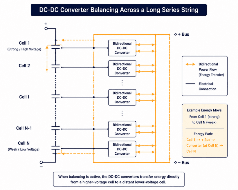
DC-DC converter active balancing hardware topologies use a dedicated converter, commonly a buck-boost or flyback design.
That converter moves energy between any two points in the string, not just neighbors, so it doesn’t need a long hop-by-hop transfer path.
Bidirectional converters pull energy from a strong cell and push it into a weak cell in one stage. Some route it through the pack’s main bus instead.
Why DC-DC Converters Dominate Utility-Scale Deployments
Any-cell-to-any-cell transfer is the main reason DC-DC converter topologies show up in most modern utility-scale LFP racks.
Commercial hardware backs that up with real numbers. Production balancing ICs for lithium and LiFePO4 packs commonly support up to 10A of balancing current — several orders of magnitude above the resistor-limited milliamp range typical of passive balancing.
A two-hundred-cell string with one weak cell near the far end doesn’t need a hundred hops to fix. Instead, a converter-based circuit reaches it directly.
The trade-off is control complexity. A converter-based BMS needs firmware smart enough to pick which cells to address, and in what order.
It isn’t just reacting to whichever neighbor pair shows the biggest voltage gap. Instead, it has to plan the whole string.
Active Balancing Hardware Topologies Compared
The table below lines up all three active balancing hardware topologies side by side, on the factors that matter most for a BESS design decision.
| Topology | Typical Balancing Current | Transfer Path | Relative Cost | Best Fit |
|---|---|---|---|---|
| Switched-Capacitor | Under 1A | Adjacent cells only | Lowest | Small packs, low cell counts |
| Switched-Inductor | ~0.9–1A (908 mA measured in a 2025 prototype) | Adjacent cells only | Low–Moderate | EV packs, LFP BESS submodules needing more current than capacitor circuits |
| Transformer-Based | 1-5A | Any cell, via shared winding set | Moderate-High | Mid-size strings needing fast correction |
| DC-DC Converter | 1-5A | Any cell to any cell | Moderate | Utility-scale LFP racks, 200+ cells in series |
Choosing Active Balancing Hardware Topologies for Your Next BESS Design
Picking between active balancing hardware topologies comes down to three filters, applied in order.
String length is the first filter. Short strings can tolerate a slow, cheap switched-capacitor circuit. Long strings can’t.
Balancing speed is the second filter. A rack that must correct imbalance within one charge cycle needs a converter-based or transformer-based design, not a capacitor-hopping one.
Switched-inductor sits between the two — faster than switched-capacitor, but still adjacent-cell only, so it suits mid-size strings more than a 200+ cell utility rack.
Budget per rack is the third filter. It usually settles the choice between transformer-based and DC-DC converter circuits, once the first two questions are answered.
Frequently Asked Questions
What’s the difference between active and passive cell balancing hardware?
Passive balancing burns excess energy as heat through a resistor. Active balancing hardware topologies move that energy to a weaker cell instead, using a capacitor, transformer, or converter as the transfer path. See the In-Service Cell Imbalance guide for when each approach makes sense.
Which active balancing hardware topology is most common in utility-scale BESS?
DC-DC converter topologies. Their any-cell-to-any-cell transfer path suits the long series strings found in grid-scale LFP racks, where switched-capacitor circuits would need too many hops to reach a distant cell.
How does switched-inductor balancing compare to switched-capacitor?
Both are adjacent-cell-only topologies, but switched-inductor tolerates higher current and larger voltage differentials. A 2025 peer-reviewed 22-cell prototype measured 908 mA balancing current at 84% efficiency, correcting a 1.18V imbalance to 0.47V in about 2.5 hours — meaningfully faster than a typical switched-capacitor design, though still slower than transformer-based or DC-DC converter circuits for long strings.
Do active balancing hardware topologies add much cost to a BESS design?
Yes, relative to passive balancing. Active balancing ICs add a converter, transformer, or switch-matrix stage that passive resistor balancing doesn’t need. But that cost sits in the BMS layer, not the cell or pack hardware, so it’s a small fraction of total rack cost even though it’s a real line item.
Can a BESS mix active balancing hardware topologies within the same string?
Not usually within a single string, since the BMS firmware is built around one transfer method. Mixed hardware more commonly shows up when comparing designs across racks or augmentation phases, not inside one string.
Further Reading
- In-Service Cell Imbalance in LFP BESS
- Designing an LFP BESS Against SOC Drift, Cell Imbalance, and Premature Cutoffs
- EKF SOC Estimation Design for LFP BESS
- Integrated BMS Control Architecture
- Dynamic, DCIR-Adaptive Voltage Cutoff Design for LFP BESS
References
- ScienceDirect – Multi-winding transformer-based active cell equalizer for series-connected Li-ion batteries
- Discover Energy (Springer) – A state-of-the-art review on battery cell balancing strategies
- Pinto, J.G.O.; Miranda, J.P.D.; Barros, L.A.M.; Afonso, J.A. Development of Modular BMS Topology with Active Cell Balancing. Batteries 2025, 11, 421. MDPI (peer-reviewed, open access)
- Miranda, J.P.D.; Barros, L.A.M.; Pinto, J.G. A Review on Power Electronic Converters for Modular BMS with Active Balancing. Energies 2023, 16, 3255. MDPI (peer-reviewed, open access)