
Earthing (Grounding) for a Battery Energy Storage System (BESS): A Complete Design Guide
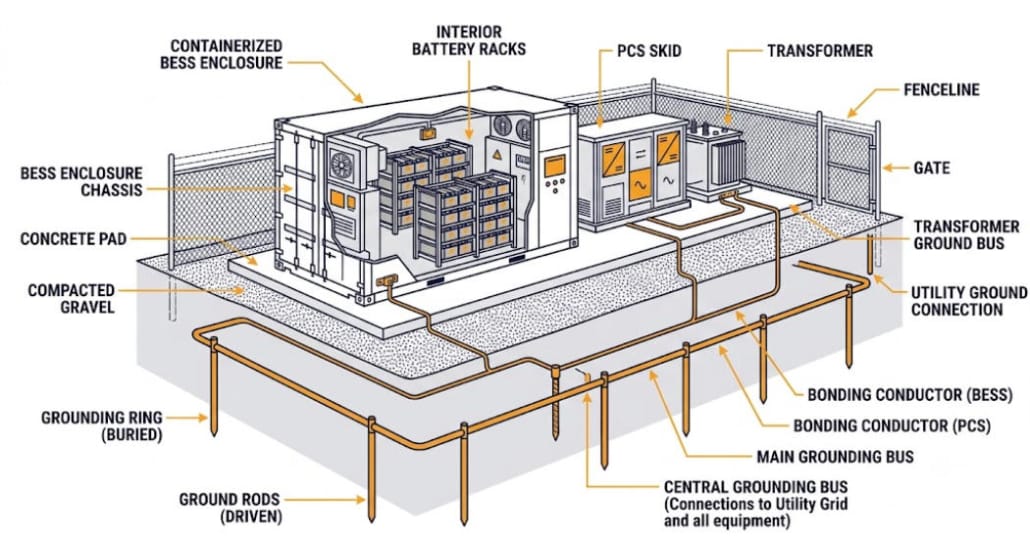
A BESS grounding system ties every battery rack, enclosure, and steel structure back to a common earth point. So, when a fault happens, current gets a fast path home. But get the BESS grounding system wrong, and one insulation fault can turn a cabinet into a shock hazard. It can also start a slow fire risk. So this guide covers the earthing methods, code rules, and design steps that keep a battery storage site safe. First, it covers soil testing. Then it covers ground grid sizing.
| Quick Answer A BESS grounding system bonds every metal part of a battery storage site to a common earth reference. Earthing is the term IEC-based countries use. Grounding is the U.S. term. But both mean the same thing. In the U.S., NEC Article 706 sets the rules for systems above 50V AC or 60V DC. Meanwhile, most other countries follow IEC 60364 instead. That standard defines TN, TT, and IT earthing systems. Also, a strong BESS grounding system needs a buried grounding electrode system. Many modern DC buses add high-resistance grounding too. So an insulation monitoring device watches for faults, instead of a solid ground wire alone. |
Why a BESS Grounding System Matters
Grounding is not paperwork. Instead, it decides whether a fault trips a breaker in milliseconds. Or, it decides whether a fault energizes a cabinet a technician is standing next to. A BESS site packs high fault current into a small footprint. Also, workers open enclosures often for maintenance. So the margin for error stays thin.
Personnel Safety
A bonded enclosure stays close to earth potential during a fault. But without that bond, a failure inside a battery cabinet can raise the metal casing to a dangerous voltage. Then anyone touching it completes the circuit. So this is the core safety case behind every BESS grounding system, at any project size.
Equipment and Fire Protection
A fast, low-impedance fault path lets breakers clear a ground fault quickly. Otherwise, the fault can grow into an arcing fault. And arcing near lithium-ion cells is a real ignition risk.
Our BESS short-circuit protection guide covers that risk in detail. So a sound BESS grounding system and short-circuit protection work as one safety strategy, not two separate items.
Protective-Device Coordination
Relays and fuses only work as fast as the fault path allows. But a weak ground path slows fault detection down. As a result, a fault can stay energized far longer than planned. So grounding design and protection coordination need to be solved together.
Earthing vs. Grounding: Same Idea, Different Vocabulary
Earthing and grounding name the same practice. First, IEC-based markets say earthing. That includes the UK, the EU, Australia, and most of Asia. Then, NEC-based markets say grounding. The United States is the main example. Still, both terms mean bonding conductive parts to earth for safety. So this guide uses both terms, matching whichever code applies to a given project.
Codes and Standards Behind a BESS Grounding System
No single global code covers earthing for battery storage. Instead, a BESS grounding system usually has to satisfy several overlapping standards. So the table below summarizes the main ones.
| Standard | Region | What It Covers |
|---|---|---|
| NEC (NFPA 70) Article 706 | United States | Covers permanently installed ESS above 50V AC or 60V DC. Sets bonding, disconnect, and circuit-protection rules |
| IEC 60364 | International | Defines TN, TT, and IT earthing system classes for low-voltage installations |
| IEEE Std 80 | International reference | Guide for AC substation grounding. Sets step- and touch-voltage limits for larger ground grids |
| IEEE Std 142 (Green Book) | International reference | General power-system grounding practice, covering equipment and system grounding |
| NFPA 855 | United States | ESS siting and spacing, which pairs with grounding design |
For example, NEC Article 706 sets the U.S. baseline for a BESS grounding system. Also, our NFPA 855 guide covers the fire-code side of siting and spacing. Meanwhile, lightning protection sits alongside a BESS grounding system, not inside it. We cover that later in this guide.
NEC Article 706’s scope line matters most for design choices. So it applies to any permanently installed ESS above 50V AC or 60V DC. That covers nearly every commercial and utility-scale BESS grounding system built today.
Types of Earthing Systems in a BESS Grounding System
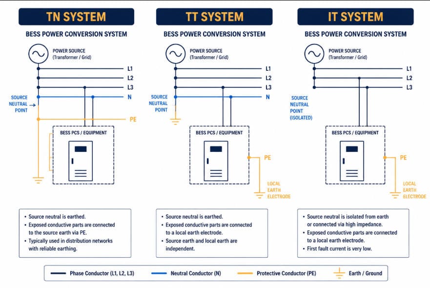
TN, TT, and IT Systems (IEC 60364)
IEC 60364 uses a two-letter code for each earthing system. First, the first letter shows how the source relates to earth. Then, the second shows how equipment is earthed. TN systems bond equipment to the source’s earthed neutral. So that gives fast fault clearance through ordinary breakers. TT systems instead use a separate, independent earth electrode at the site. They rely on residual-current devices to catch smaller faults. IT systems isolate the source from earth, or use high impedance instead. So this favors continuity of supply over instant clearance. It is a common choice for critical DC sections.
See this IEC 60364 earthing system overview for the full classification breakdown.
Solidly Grounded, Ungrounded, and High-Resistance Grounded DC Buses
The battery-side DC bus needs its own decision, separate from the AC earthing system. First, older, PV-derived designs often grounded the DC bus solidly. Then a ground-fault detector-interrupter opened the bond on a fault. Today, many modern, transformerless power conversion systems instead run the DC bus ungrounded or high-resistance grounded. So an insulation monitoring device watches it continuously, instead of a fuse-based interrupter. The table below compares all three approaches.
| Approach | Fault Detection | Typical BESS Use |
|---|---|---|
| Solidly grounded | Fast — an overcurrent device clears the fault path directly | Legacy PV-battery hybrids, some low-voltage residential or C&I designs |
| Ungrounded (floating) | Continuous insulation-resistance monitoring, no automatic first-fault trip | Modern transformerless PCS topologies where uptime matters most |
| High-resistance grounded | Limits fault current while a monitoring device flags the fault | Utility-scale strings and central PCS designs balancing safety and uptime |
This choice depends heavily on PCS topology. So it belongs in the same conversation as PCS overvoltage protection and grid-forming versus grid-following control. It should never be bolted on after the fact.
Core Components of a BESS Grounding System
Equipment Grounding and Bonding in a BESS Grounding System
Every metal enclosure, rack, and structural part needs a bonding jumper. That jumper must reach back to the grounding system. Also, it needs to be sized for the worst-case fault current. First, painted surfaces need a bare-metal bonding point, since paint is an insulator. Also, fence gates and conduit expansion joints need flexible jumpers, so thermal movement never breaks continuity.
Conductor size follows the code, not a guess. So the table below gives quick reference points for both major code families.
| Reference | Basis | Quick Rule |
|---|---|---|
| NEC Table 250.66 (GEC sizing) | Size of the largest ungrounded service conductor | A GEC run solely to a rod, pipe, or plate electrode never needs to exceed 6 AWG copper |
| NEC Table 250.122 (EGC sizing) | Rating of the upstream overcurrent device | Equipment grounding conductors scale with breaker or fuse size, not with the circuit conductor size |
| IEC 60364-5-54 (PE sizing) | Cross-sectional area of the phase conductor | PE equals the phase size up to 16 mm², stays at 16 mm² up to 35 mm², then drops to half the phase size above that |
The Grounding Electrode System
This is the buried hardware that gives fault current a path into the earth. It can be ground rods, a ground ring, or a full mesh grid. So, site size drives the choice. First, a small C&I rooftop or pad-mounted BESS can use a simple rod-based electrode system. Then, a utility-scale site instead needs a buried copper mesh grid. That grid must meet IEEE 80 step- and touch-voltage limits.
Grounding a Containerized or Mobile BESS
Containerized and trailer-mounted BESS units add a wrinkle. Often, they sit on gravel, asphalt, or a temporary pad, not poured concrete. So a concrete-encased electrode is rarely an option there. Instead, crews drive temporary ground rods, or lay a portable ground mat, at each deployment site. Also, every container or trailer section needs a bonding strap back to that temporary electrode, plus jumpers between linked sections. Since soil conditions change from site to site, resistance needs a fresh test at every new location, not just once back at the factory.
DC Ground-Fault Detection and Insulation Monitoring
On the DC side, ground-fault detector-interrupters and insulation monitoring devices solve the same problem in different ways. Both catch a fault between a live conductor and ground before it becomes an arc. Also, an insulation monitoring device measures leakage resistance continuously. So it raises an alarm well before resistance drops to a dangerous level. That is why it has become the default choice on ungrounded and high-resistance grounded DC buses.
Avoiding Ground Loops in a BESS Grounding System
Power grounding is not the only ground reference on a BESS site. Comms wiring also needs care. That includes CAN bus, RS-485, or IEC 61850 links between racks, the BMS, and the PCS. So a shielded comms cable should bond to ground at one end only. Otherwise, bonding both ends creates a ground loop. Then, even a small voltage difference between the two ground points drives current through the shield. That current, in turn, induces noise onto the signal pair. Common symptoms include noisy cell-voltage readings, checksum errors, and comms dropouts, especially during heavy charge or discharge events. So plan single-point grounding for comms at design time, not after commissioning turns up faults.
Designing a BESS Grounding System’s Electrode Network
Soil Resistivity Testing
Soil resistivity, not conductor size, drives ground rod performance the most. It shifts with moisture, temperature, and soil type. So a resistivity survey should happen early in site design, not after the rods are already buried. The four-pin Wenner method is the standard test. Also, sandy or rocky soil can carry resistivity several times higher than loam. That directly raises the rod count, the grid area, or the need for ground-enhancement material.
The Concrete-Encased Electrode (Ufer Ground)
Most C&I and utility-scale BESS pads already sit on poured concrete. So that concrete can double as a grounding electrode. NEC 250.52(A)(3) allows this. A concrete-encased electrode, often called a Ufer ground, uses at least 20 feet of rebar or bare copper conductor, encased in at least 2 inches of concrete that touches the earth. Since a Ufer ground typically beats a driven rod on resistance, especially in dry or rocky soil, it is worth planning before the pour, not after. Once the concrete cures, adding one later means breaking into a finished pad.
Worked Example: Sizing Ground Rods for a C&I BESS Pad
Take a standard 8-foot, 5/8-inch copper-clad ground rod. Place it in average loam soil, with a resistivity of 100 Ω·m. Using the standard single-rod resistance formula, that rod works out to roughly 40 Ω. So that is above the 25 Ω threshold NEC 250.53(A)(2) sets for a single rod, pipe, or plate electrode. Then, a second rod, spaced at least 6 feet away, usually brings the combined resistance under that 25 Ω limit. But mutual interference between rods means the drop is never a clean 50%. In high-resistivity ground — sandy or rocky soil at 300 Ω·m or more — a single rod can exceed 100 Ω. There, the fix shifts from adding rods to a driven ground ring, chemical rods, or ground-enhancement backfill.
Step and Touch Voltage for Utility-Scale Sites
Larger sites need more than a resistance number. So IEEE Std 80 sets tolerable step- and touch-voltage limits. These depend on soil resistivity, fault-current size, and clearing time. Then, the standard works backward to the mesh spacing a ground grid needs. Still, a grid can show low overall resistance and still fail an IEEE 80 check. That happens when the voltage gradient across the grid surface runs too steep. So resistance alone is never the full design target for a utility-scale BESS grounding system.
See this IEEE Std 80 grounding interpretation for the underlying safety criteria.
Lightning Protection Sits Alongside Earthing
Lightning protection systems use their own down-conductor and electrode network. NFPA 780 covers this in the U.S. IEC 62305 covers it internationally. So this network is engineered for high-frequency surge current. It stays distinct from the power-system grounding electrode system. Still, the two networks are typically bonded together at grade. That prevents a dangerous potential difference between them during a strike.
Surge protective devices on the AC and DC sides, covered in our PCS overvoltage protection guide, round out the site’s full surge coordination plan.
Common BESS Grounding System Mistakes
- Treating a painted enclosure surface as a bonding point, instead of scraping to bare metal first.
- Installing a single ground rod without testing resistance, then assuming it clears the NEC 25 Ω threshold.
- Skipping flexible bonding jumpers across fence gates and conduit joints, which breaks continuity as materials move.
- Solidly grounding a DC bus on a transformerless PCS without checking manufacturer guidance, which can cause nuisance trips.
- Sizing a ground grid to a resistance target alone, with no IEEE 80 step- and touch-voltage check on a utility-scale site.
- Bonding bare copper directly to galvanized steel rebar or racking in humid or coastal soil, which speeds up galvanic corrosion at the connection point.
- Never re-testing soil resistivity or ground resistance after commissioning, even though seasonal moisture changes both.
Key Takeaways
- A BESS grounding system bonds every conductive part to a common earth reference. That gives fault current a defined, low-impedance path home.
- NEC Article 706 governs U.S. installations above 50V AC or 60V DC. IEC 60364’s TN, TT, and IT classes govern most other markets.
- Many modern, transformerless PCS designs run the DC bus ungrounded or high-resistance grounded. An insulation monitoring device watches it instead of a solidly grounded fuse-based interrupter.
- A single ground rod in average soil rarely meets NEC’s 25 Ω threshold alone. Test soil resistivity before the rods go in the ground, not after.
- A poured concrete BESS pad can double as a Ufer ground under NEC 250.52(A)(3), often beating a driven rod on resistance in dry or rocky soil.
- Keep comms shields single-point grounded. Bonding both ends of a CAN bus, RS-485, or IEC 61850 shield creates a ground loop that shows up as noisy readings and comms dropouts.
- Utility-scale sites need an IEEE 80 step- and touch-voltage check. A low resistance reading alone does not guarantee a safe voltage gradient.
- Lightning protection and power-system grounding are separate networks. Bond them together at grade; do not treat them as one system.
- Grounding design, short-circuit protection, and overvoltage protection form one coordinated safety strategy, not three separate checklists.
Frequently Asked Questions
Does the NEC Require a BESS Grounding System?
Yes. For any permanently installed ESS above 50V AC or 60V DC, NEC Article 706 sets bonding, disconnect, and circuit-protection rules. These form the core of a compliant BESS grounding system.
What Ground Resistance Does a BESS Grounding System Need?
The NEC benchmark for a single rod, pipe, or plate electrode is 25 Ω or less. If one rod misses that mark, add a supplemental rod at least 6 feet away. Utility-scale sites also need an IEEE 80 step- and touch-voltage check, on top of a lower target resistance.
Should a BESS DC bus be grounded or ungrounded?
It depends on the PCS topology. Many modern, transformerless designs use an ungrounded or high-resistance grounded DC bus with continuous insulation monitoring. Some legacy or transformer-based designs still solidly ground the bus with a ground-fault detector-interrupter. Follow the PCS manufacturer’s guidance rather than a default assumption.
Does a Containerized or Mobile BESS Need Different Grounding?
Yes, somewhat. A fixed pad lets a BESS grounding system use a concrete-encased electrode. A mobile or trailer-mounted unit usually cannot rely on that. So it needs temporary ground rods or a portable ground mat at each site, plus fresh resistance testing every time it moves.
How often should a BESS grounding system be tested?
Test ground resistance and bonding continuity at commissioning first, using a fall-of-potential test or a clamp-on ground resistance tester. Then, re-test on a regular maintenance schedule. Soil resistivity shifts with seasonal moisture and temperature, so a compliant reading at commissioning can drift over time.
Further Reading
- BESS Short Circuit Protection
- PCS Overvoltage Protection
- Understanding BESS Specifications
- NFPA 855 Guide
- LVRT and HVRT Ride-Through
- Grid-Forming vs. Grid-Following BESS
- BESS PCS Functions and Features
- NEC Article 706 overview (up.codes)
- IEEE Std 80 substation grounding interpretation (standards.ieee.org)
- IEC 60364 earthing system classification overview (ecalpro.com)


Leave a Reply
Want to join the discussion?Feel free to contribute!