Every BESS project faces the same early choice: string vs centralized BESS design for the PCS. This one choice sets fault behavior, efficiency, and long-term cost.
Both designs store energy in the same LFP racks. So what changes? Just how the PCS wires up. Still, that single choice shapes the whole project.
Quick Answer In a string vs centralized BESS comparison, string BESS gives each battery cluster its own PCS. A fault stays isolated. Each cluster also runs closer to peak efficiency.Centralized BESS uses one large PCS for the whole array. It costs less per kW. But it risks taking the entire block offline if that one unit fails.Utility-scale, cost-driven projects often pick centralized PCS. C&I and uptime-critical sites often pick string PCS instead.
What Is PCS Topology in a BESS?
The PCS is the bidirectional inverter in a BESS. It turns battery DC power into grid AC power. Then it also flips AC back to DC during charging.
PCS topology just means two things. First, how many PCS units a project uses. Second, how each one wires into the battery racks. Two topologies lead the market: centralized and string.
A modular hybrid approach also exists. It borrows a bit from both sides of the string vs centralized BESS divide.
What Is Centralized BESS?
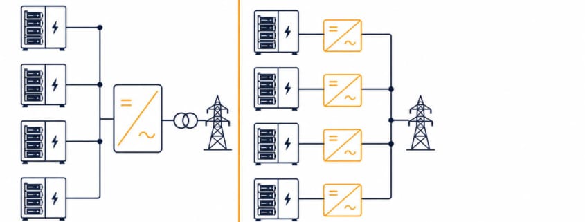
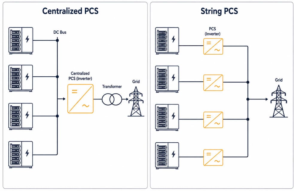
Centralized BESS is a battery storage design that routes every battery cluster through one large, shared PCS. So one or a few big inverters handle the whole array’s power conversion.
Think of it as a single hub. All the DC power flows to one point before it turns into grid-ready AC power. That hub is efficient to build, but it is also a single point of failure.
What Is String BESS?
String BESS is a battery storage design that gives each battery cluster its own dedicated PCS. So there is no shared hub. Every cluster converts its own power independently.
Picture a set of parallel lanes instead of one funnel. Each lane runs on its own, so one blocked lane never stops traffic in the others. That is the core idea behind a string vs centralized BESS layout.
How Centralized PCS Architecture Works
A centralized design uses one or a few large inverters for the whole array. Every cluster feeds a shared DC bus. Then that bus feeds a single converter.
Picture a typical utility-scale block. It might pair four 2.5 MW inverters with a 10 MW, 40 MWh array. Each inverter connects to one medium-voltage transformer.
Modern central PCS units handle 1 MW to 10 MW per inverter. Peak conversion efficiency is high — commonly in the high-90s percent range. But weighted-average efficiency at real-world load is what actually matters for revenue, and it always runs lower than the peak number.
Centralized PCS Advantages
Lower cost per kW once a project reaches utility scale
Fewer transformers, combiner boxes, and cable runs
Simpler control setup, since fewer units need coordination
Centralized PCS Trade-offs
A single fault can take the whole battery block offline until repair
Efficiency drops at partial load, and most systems run below full output most of the time
A larger footprint per unit complicates transport and crane access
How String PCS Architecture Works
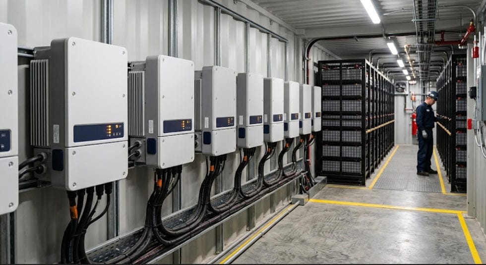
String architecture gives each battery cluster its own dedicated PCS. Each cluster’s DC output goes straight to its own converter. So it never touches a shared bus.
Compact C&I string units run far smaller than their utility-scale counterparts. Utility-scale string units run larger — and they keep growing.
In 2025, a 400 kW+ string PCS module reached the utility-scale market, built for large containerized deployments, according to ESS News. That single data point shows how far string PCS has moved past its old C&I-only reputation.
Since each string works on its own, one unit can shut down for maintenance. Meanwhile, the rest of the array keeps running without a hiccup.
String PCS Advantages
Fault isolation — a failed unit only affects its own cluster
Better partial-load performance across clusters with uneven aging or temperature
Easier phased expansion, since a project can add capacity string by string
String PCS Trade-offs
More total units to install, wire, and monitor
Slightly higher balance-of-plant cost in most designs
More interconnection points, which adds commissioning time
Centralized BESS: Features and Functions
In the string vs centralized BESS split, a centralized PCS handles the same core job as any inverter.
See our BESS PCS Functions and Features guide for the full list. But a centralized design delivers those functions from one shared unit, not many.
DC-to-AC and AC-to-DC conversion for the entire array, from a single converter
One grid-forming or grid-following control loop governs the whole block
Protection functions — over-voltage, over-current, short-circuit — apply at one point, covering every cluster behind it
Reactive power and power factor control dispatched from a single, larger unit
One data and monitoring point, which simplifies SCADA integration
This concentration is exactly what makes centralized PCS cost-efficient. It is also exactly what makes a single fault so costly.
String BESS: Features and Functions
On the string side of the string vs centralized BESS split, the PCS performs the same core functions.
See our BESS PCS Functions and Features guide for the full list. The difference is that every cluster gets its own copy of them.
DC-to-AC and AC-to-DC conversion happens per cluster, not once for the whole array
Each unit runs its own grid-forming or grid-following control loop, independent of the others
Protection functions trip at the cluster level, so a fault never reaches healthy strings
Reactive power dispatch is finer-grained — each string can be commanded separately
Monitoring is far more granular, since every cluster reports its own data
That granularity is the trade for a higher unit count. More data, more control points, and more independence — at the cost of more hardware to manage.
How Functions Differ Between String and Centralized BESS
Both topologies run the same core PCS functions. The string vs centralized BESS split is about where those functions live, and how finely they’re applied.
Function
Centralized PCS
String PCS
Control loop
One loop for the whole array
One independent loop per cluster
Protection scope
Trips can affect the whole block
Trips stay isolated to one cluster
Reactive power dispatch
Coarse — set at the array level
Fine — set per cluster
Monitoring granularity
Array-level data
Cluster-level data
SCADA complexity
Simpler — fewer points to poll
More complex — more points to poll
String vs Centralized BESS: Key Differences
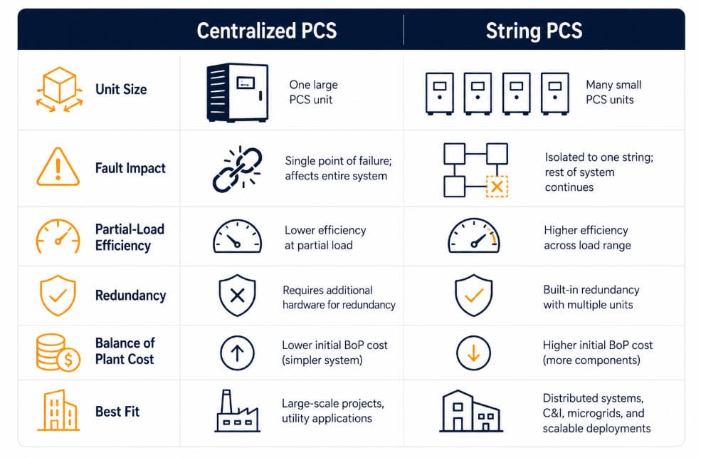
The table below lines up the string vs centralized BESS choice against the factors that matter most for planning.
Factor
Centralized PCS
String PCS
Typical unit size
1–10 MW per inverter
Well under 1 MW per unit
Fault impact
Can affect the entire block
Isolated to one cluster
Partial-load efficiency
Lower at reduced output
Higher across varying loads
Redundancy
Needs spare or N+1 units
Built in through unit count
Balance-of-plant cost
Lower per kW at scale
Higher per kW, more units
Best fit
Large, uniform utility-scale sites
C&I and uptime-critical sites
Redundancy and Fault Isolation in String vs Centralized BESS
In a centralized design, one PCS fault removes the whole block from service. Then the other clusters sit idle, since they all share the same converter.
A string design isolates that same fault to one cluster. So the rest of the array keeps charging or discharging without a break.
This isn’t just a vendor talking point. Sandia National Laboratories’ Energy Storage Handbook, Chapter 13 describes the same trade-off in modular, multi-converter PCS designs. If one converter or storage unit must be taken offline, the rest of the system keeps operating. It runs at reduced capacity, but it doesn’t stop entirely.
This gap matters most for revenue-critical work. Once a system goes offline, frequency-response contracts, backup deals, and peak-shaving windows all carry a real cost.
Efficiency and Partial-Load Performance
Peak efficiency between the two topologies is often close. Neither has a dramatic edge at full output.
But the real gap shows up at partial load. Most BESS assets spend most of their life below full output, not at it.
String units track their own cluster’s charge and temperature. So each one runs nearer its own peak efficiency point.
Distributed control also helps on sites with uneven cluster aging. A 2025 study on two-string BESS balancing, published on arXiv, tested independent, balanced control of separate battery strings. Versus a coupled baseline, it improved inverter efficiency by about 1.5 percentage points and derating efficiency by about 2 points.
Cost and O&M Considerations
Centralized PCS lowers upfront cost per kW. Fewer, larger units mean fewer transformers, less cabling, and fewer combiner and interconnection points — all balance-of-plant items that add up fast in a string design.
String PCS raises the unit count. Then that adds wiring, monitoring points, and commissioning time.
Still, field maintenance is often simpler per event. A technician can swap one unit without derating the rest of the array.
Yet neither cost profile holds everywhere. Site labor rates, transformer lead times, and financing terms all shift the real-world number in a string vs centralized BESS budget.
Which Architecture Fits Your String vs Centralized BESS Decision?
The right choice depends on scale and uptime needs, not on price alone. First, weigh how much a fault would actually cost you.
Project Type
Typical Choice
Why
Utility-scale, uniform site
Centralized
Lower cost per kW; simpler design outweighs the redundancy gap
C&I or frequency-response asset
String
Fault isolation and better partial-load performance protect revenue
Mixed shading or phased buildout
String
Independent cluster control captures a documented efficiency gain
Cost-constrained, fault-tolerant site
Centralized + N+1 spare
Keeps the low-cost benefit while covering the single-point-of-failure risk
Best PCS Choice by Project Type
The table above covers the general split. But real projects fall into more specific categories. Here’s how the string vs centralized BESS call plays out in practice.
Utility-scale solar-plus-storage (50+ MWh): Go centralized. Site conditions are usually uniform. So the cost savings outweigh the fault-isolation gap. Add N+1 spares if the offtake contract penalizes downtime.
C&I behind-the-meter (500 kWh–5 MWh): Go string. These sites often run at partial load most of the day. So a single fault taking out the whole system is a bigger business risk at this scale.
Frequency response and ancillary services: Go string. Revenue depends on being online and dispatchable. Losing the whole asset to one fault can mean a contract penalty, not just lost output.
Microgrids and islanded sites: Go string. Grid-forming duties often split across multiple units for redundancy. So an islanded site can keep forming voltage even if one string trips.
Data center backup power: Go string, or a hybrid layout. Uptime requirements are strict. Cluster-level fault isolation matches the redundancy philosophy data centers already use elsewhere.
Phased or multi-year buildouts: Go string. Capacity can be added string by string as budget grows. That avoids resizing a large central inverter up front.
Cost-constrained utility projects with firm redundancy needs: Go centralized, but budget for N+1 spare units. This keeps the lower cost-per-kW while covering the single-point-of-failure risk.
String vs Centralized BESS: Key Takeaways
Key Takeaway
1. Centralized PCS uses fewer, larger inverters and costs less per kW at utility scale.
2. String PCS gives each cluster its own inverter, isolating faults and improving partial-load efficiency.
3. Peak efficiency is similar between the two — the real gap shows up at partial load and during faults.
5. An N+1 centralized design can add redundancy without a full switch to string architecture.
Frequently Asked Questions About String vs Centralized BESS
What is the main difference in a string vs centralized BESS comparison?
Centralized BESS routes every battery cluster through one large PCS. String BESS gives each cluster its own smaller PCS instead. So faults and performance stay isolated per cluster.
Is string PCS more efficient than centralized PCS?
At full load, the two are close. But at partial load, where most systems run most of the time, string PCS usually wins. Since each unit tracks its own cluster’s condition.
Which topology costs less?
Centralized PCS usually costs less per kW upfront. This comes mainly from fewer transformers and simpler cabling. Still, string PCS can offset that gap over time through easier fault isolation.
Can a BESS use both string and centralized PCS?
Yes. Some projects use a modular hybrid layout instead. This groups several clusters per mid-sized PCS. It splits the difference between cost and fault isolation.
Does PCS topology affect fire and safety compliance?
Topology does not change NFPA 855 compliance directly. But faster fault isolation in a string design can support the hazard mitigation analysis a project needs for permitting.
Summing up the string vs centralized BESS choice
Once you know your uptime needs, the string vs centralized BESS decision gets simpler. Start with fault cost, then let scale and budget settle the rest.
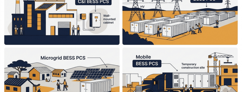
The BESS PCS — Power Conversion System — converts DC battery power to AC for loads or the grid. However, what a PCS must do beyond that basic job changes completely depending on the application. Consequently, choosing the wrong PCS type is one of the most expensive mistakes a project team can make.
Consider four scenarios. A factory running peak shaving needs a PCS that switches to backup mode within 20 ms. By contrast, a 200 MW grid project needs sub-200 ms frequency response and reactive power control. An island microgrid, meanwhile, needs the PCS to synthesise the AC voltage reference — because no utility connection exists at all. Finally, a mobile BESS on a trailer needs ruggedness and fast site commissioning above all else.
Therefore, this guide covers each of the four application types in detail. Furthermore, it includes a master comparison table so you can see exactly which PCS functions are mandatory, optional, or not needed for each system type. By the end, you will have a clear framework for evaluating any BESS PCS proposal.
What Is a BESS PCS?
Inside every battery energy storage system, the Power Conversion System converts DC from the battery cells to AC for loads or the grid. During charging, it reverses direction and converts AC back to DC. Crucially, both functions share a single hardware platform — hence the term bidirectional.
As Sunlith’s PCS vs. Inverter guide explains, a PCS includes far more than just a bidirectional inverter. In addition, it handles reactive power control, protection functions, grid synchronisation, and communication with the BMS and EMS. According to NLR’s Power Electronics research, the PCS is one of the most critical components in grid-connected storage — because its control functions directly determine grid stability and service quality.
Moreover, the Bidirectional Inverter vs PCS comparison on this site highlights PCS-specific capabilities — including multi-port DC support, islanding, and black start. None of these are available in a stand-alone inverter. However, which of these capabilities you actually need depends entirely on your application type.
Four Application Types at a Glance
Before diving into each type, here is a quick overview showing how the four BESS application categories differ in their primary PCS priorities.
System Type
Typical Power
Grid Connection
Primary PCS Priority
C&I (Behind-the-Meter)
30 kW – 2 MW
Grid-connected, LV/MV
Peak shaving, backup power, solar integration
Utility Scale (Front-of-Meter)
2 MW – 500 MW+
Grid-connected, MV/HV
FFR, reactive power, grid code compliance
Microgrid / Off-Grid
10 kW – 50 MW
Islanded or weak grid
Grid-forming, black start, load following
Mobile BESS
50 kW – 5 MW
Temporary grid or off-grid
Portability, ruggedness, fast commissioning
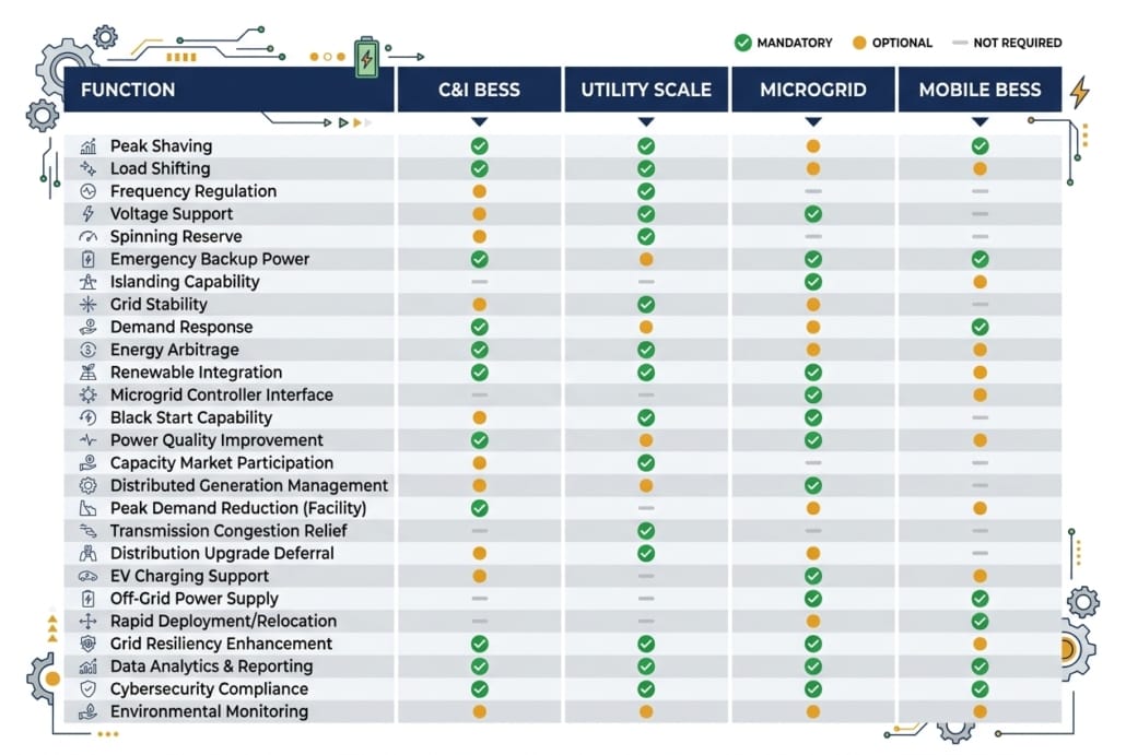
Master Comparison Table: BESS PCS Functions by Application Type
Use this table to compare PCS requirements across all four system types. Functions marked ✔ Mandatory must be specified and tested. Those marked ◉ Optional are recommended in certain site conditions. Those marked ✘ Not Required are not applicable to that system type.
PCS Function / Feature
C&I BESS
Utility Scale
Microgrid / Off-Grid
Mobile BESS
Bidirectional AC-DC Conversion
✔ Mandatory
✔ Mandatory
✔ Mandatory
✔ Mandatory
Peak Shaving / Load Shifting
✔ Mandatory
✘ Not Required
✘ Not Required
◉ Optional
Seamless Transfer / UPS Mode
✔ Mandatory
✘ Not Required
✔ Mandatory
✔ Mandatory
Solar PV Integration (AC/DC)
✔ Mandatory
◉ Optional
✔ Mandatory
◉ Optional
Fast Frequency Response (FFR)
✘ Not Required
✔ Mandatory
✘ Not Required
✘ Not Required
Primary Frequency Response (PFR)
✘ Not Required
✔ Mandatory
◉ Optional
✘ Not Required
Reactive Power (Q) Control
◉ Optional
✔ Mandatory
◉ Optional
✘ Not Required
LVRT / HVRT (Ride-Through)
◉ Optional
✔ Mandatory
✘ Not Required
◉ Optional
Grid-Following Mode (GFL)
✔ Mandatory
✔ Mandatory
◉ Optional
✔ Mandatory
Grid-Forming Mode (GFM)
✘ Not Required
◉ Recommended
✔ Critical
◉ Optional
Black Start Capability
✘ Not Required
◉ Optional
✔ Critical
◉ Optional
Droop Control
✘ Not Required
◉ Optional
✔ Critical
◉ Optional
Load Following
✘ Not Required
✘ Not Required
✔ Critical
◉ Optional
Genset Synchronisation
✘ Not Required
✘ Not Required
✔ Critical
✔ Mandatory
Time-of-Use (TOU) Scheduling
✔ Mandatory
✘ Not Required
✘ Not Required
◉ Optional
Multi-Port DC Input (PV + Battery)
◉ Optional
✘ Not Required
✔ Mandatory
◉ Optional
IEC 61850 / SCADA Integration
✘ Not Required
✔ Mandatory
◉ Optional
✘ Not Required
Modbus TCP / EMS Communication
✔ Mandatory
✔ Mandatory
✔ Mandatory
✔ Mandatory
Wide DC Input Voltage Range
✘ Not Required
✘ Not Required
✔ Mandatory
✔ Mandatory
Overload Capability (150–200%)
✘ Not Required
✘ Not Required
✔ Critical
✔ Mandatory
Compact / Trailer-Mount Design
✘ Not Required
✘ Not Required
✘ Not Required
✔ Critical
Rapid Commissioning (< 4 hrs)
✘ Not Required
✘ Not Required
✘ Not Required
✔ Critical
IP55+ Outdoor Enclosure
◉ Optional
✔ Mandatory
✔ Mandatory
✔ Critical
Noise Level < 65 dB(A)
✔ Mandatory
✘ Not Required
◉ Optional
◉ Optional
NERC CIP / Cybersecurity
✘ Not Required
✔ Mandatory
✘ Not Required
✘ Not Required
Legend: ✔ Mandatory = must be specified and verified at FAT | ◉ Optional = recommended for certain conditions | ✘ Not Required = not applicable
Which PCS functions are mandatory, optional, or not needed? This comparison covers all four BESS application types in one quick-reference chart.
C&I BESS PCS Functions and Features
A C&I — Commercial and Industrial — BESS sits behind the utility meter, serving loads inside a building or factory. Unlike utility systems, its PCS does not need to meet grid operator mandates. Instead, it must respond to site-level conditions to deliver financial returns. Specifically, the financial case comes from cutting demand charges, shifting energy to cheap tariff windows, and providing backup power during outages.
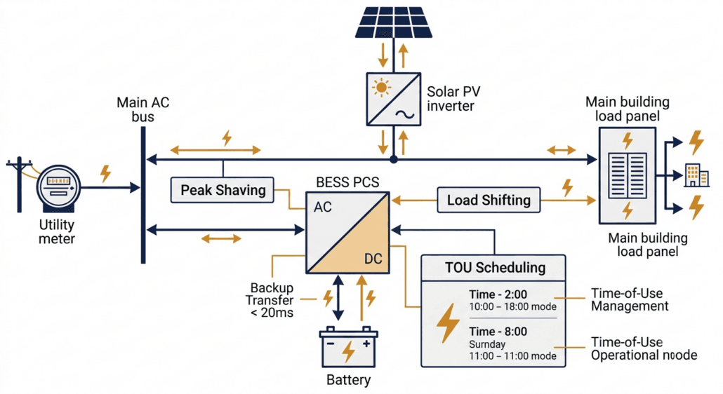
In a C&I system, the PCS manages power flow between the utility meter, solar array, and site loads — all simultaneously.
Peak Shaving and Time-of-Use Scheduling
Peak shaving is the most financially important C&I BESS PCS function. Demand charges can account for 30–50% of a commercial electricity bill. Therefore, the PCS charges the battery during low-demand periods and then discharges during peak demand to reduce the demand reading at the meter. Furthermore, time-of-use (TOU) scheduling shifts energy consumption into cheaper tariff windows, reducing energy cost on top of the demand saving.
Both functions require the PCS to support scheduled cycles via the EMS. Additionally, the PCS must respond to dynamic tariff signals from the utility in real time. As the IEA’s Grid-Scale Storage report notes, demand-side flexibility is one of the fastest-growing commercial storage applications globally. Consequently, TOU scheduling is now a baseline requirement in most C&I BESS tenders.
Seamless Transfer and Backup Power
When the grid fails, the C&I BESS PCS must switch to island mode fast enough to protect sensitive equipment. This transfer — called a seamless transfer or UPS mode — must complete within 20 ms for most commercial sites, and within 10 ms for data centres or precision manufacturing. Critically, seamless transfer is not a standard feature on all PCS products, so buyers must list the maximum allowed transfer time explicitly in their specification.
Furthermore, the PCS must be able to supply the full site load in island mode — not just a fraction of it. Therefore, both the transfer time and the island-mode power rating must be tested during factory acceptance testing (FAT). Accepting a vendor declaration without live testing is a common and expensive commissioning mistake.
Solar PV Integration
Most C&I BESS projects include rooftop or carport solar PV, so the PCS must integrate with the solar inverter. Two integration methods are available. AC coupling connects the solar inverter and PCS on the same AC bus — straightforward to retrofit, though energy passes through two conversion stages, which adds losses. DC coupling, by contrast, connects solar panels directly to the BESS DC bus via a DC-DC converter inside the PCS. This cuts conversion losses significantly. However, DC coupling requires the PCS to support multi-port DC input, so buyers must specify this feature explicitly at procurement stage.
C&I PCS Key Specifications
Power Range: 30 kW – 2 MW continuous output
Seamless Transfer: < 20 ms to island mode (< 10 ms for critical loads)
TOU Scheduling: Via EMS with dynamic tariff integration
Solar Integration: AC-coupled or DC-coupled PV input support
Grid Code: IEEE 1547 / UL 1741-SA for LV interconnection
Noise: < 65 dB(A) at 1 m for indoor installations
Communications: Modbus TCP to site EMS or BMS
Utility Scale BESS PCS Functions and Features
A utility-scale BESS connects to the medium or high-voltage grid in front of the meter. Consequently, its PCS must comply with grid operator requirements — legal obligations rather than performance suggestions. These requirements are more precise, more rigorously enforced, and technically more demanding than anything a C&I project faces. Therefore, a utility-scale PCS is a genuinely different machine from a C&I unit, even if the basic conversion function is the same.
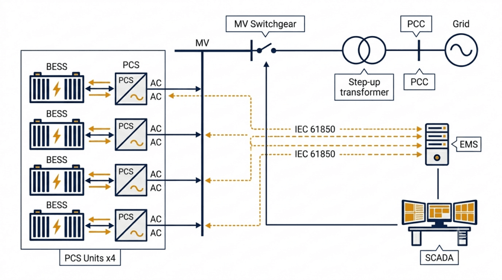
At utility scale, multiple PCS units run in parallel, feeding through a step-up transformer to the grid, with full IEC 61850 SCADA integration.
Fast Frequency Response (FFR)
FFR is the most commercially valuable utility-scale PCS function. When grid frequency drops — for example, because a large generator trips — the PCS must detect the deviation and ramp power within milliseconds. Most grid operators set the response window at 200 ms. However, some markets require 150 ms, and AEMO in Australia now tenders for sub-100 ms response.
To achieve these targets, the PCS control loop must use a dedicated high-speed frequency measurement algorithm — standard power quality meters are far too slow. Furthermore, the EMS-to-PCS communication link must have a round-trip latency below 50 ms, otherwise the communication delay consumes the available response window before the PCS even starts ramping. According to the US Department of Energy Energy Storage Grand Challenge, fast-responding battery storage is central to grid stability as thermal generation retires. Consequently, FFR is now a baseline commercial requirement for most utility-scale BESS contracts.
Reactive Power Control
Utility-scale BESS must provide reactive power — VAR — support to the grid. Under IEEE 1547-2018 in North America and EN 50549 in Europe, this function is mandatory. Specifically, the PCS must inject or absorb reactive power across all four quadrants of the PQ operating plane.
One critical detail: the PCS must deliver Q control even when the battery is at minimum state of charge — a requirement known as Q-at-night capability. Notably, some PCS products restrict reactive power output when the battery is in standby. Therefore, buyers must test Q-at-zero-kW operation during commissioning rather than rely on a datasheet claim alone.
Voltage Ride-Through: LVRT and HVRT
Grid codes require BESS to stay connected during voltage disturbances. LVRT — Low Voltage Ride-Through — means the PCS holds its grid connection during faults and injects reactive current to support the network voltage. According to ENTSO-E’s Network Code on Requirements for Generators, LVRT capability must extend down to 15% of nominal voltage for up to 625 ms. HVRT works in reverse — the PCS stays connected and absorbs reactive power during grid over-voltages.
Together, LVRT and HVRT define the voltage operating envelope of the PCS. Buyers must obtain the full voltage-time profile from the vendor and then verify it against the grid code at their specific point of interconnection. Requirements vary by country and operator, so this step cannot be skipped.
Grid-Following vs Grid-Forming at Utility Scale
Most utility-scale PCS units operate in grid-following (GFL) mode — synchronising to the grid via a Phase-Locked Loop and injecting current according to EMS setpoints. GFL works well on strong grids. However, as renewable penetration increases, grids are weakening and GFM capability is becoming more important.
Grid-forming (GFM) mode provides better fault current support and voltage stability on weak grids. As Sunlith’s Microgrid BESS technical guide notes, Australia already had over 1,070 MW of grid-forming BESS deployed by mid-2025. Therefore, GFM is mainstream technology, and buyers of utility-scale systems in high-renewable regions should evaluate it seriously.
Utility Scale PCS Key Specifications
FFR Latency: < 150–200 ms from event to ramp start
Q Control: Four-quadrant reactive power at all SOC levels including zero kW
LVRT / HVRT: Must match grid code voltage-time profile at PCC
DC Voltage: 1,000 V or 1,500 V DC to reduce cabling losses at scale
Communications: IEC 61850 GOOSE for deterministic low-latency dispatch
Cybersecurity: NERC CIP (North America) or IEC 62351 encryption
Certifications: IEEE 1547, EN 50549, AS/NZS 4777, UL 1741-SA — market-dependent
Microgrid and Off-Grid BESS PCS Functions and Features
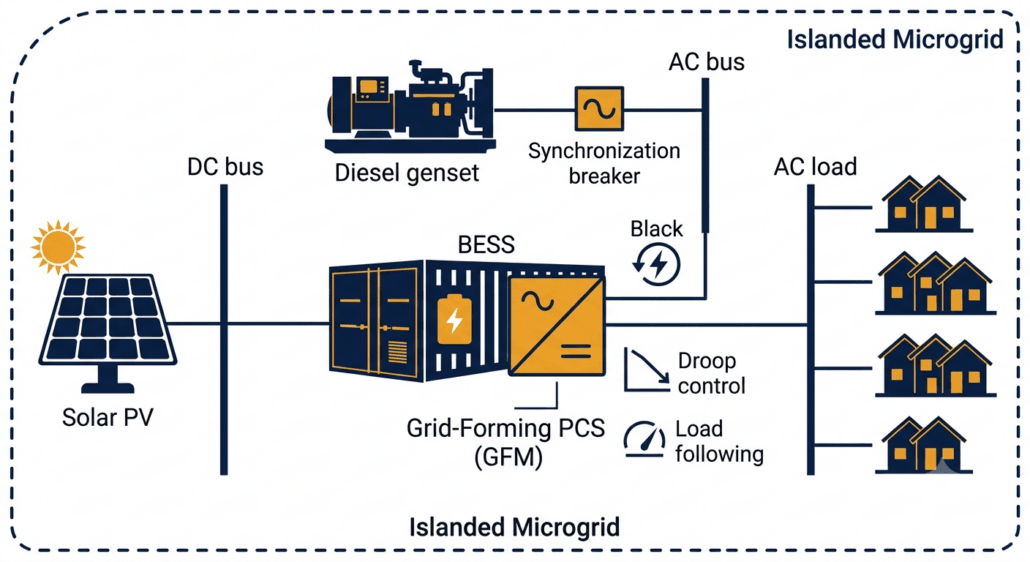
Among all four application types, an off-grid or islanded microgrid BESS places the most demanding requirements on the PCS. No utility grid exists to act as a voltage and frequency reference. Consequently, the PCS must create that reference entirely from battery power. This changes nearly everything about how the system operates — from the control architecture down to the protection coordination.
In an off-grid microgrid, the BESS PCS synthesises the local AC voltage and frequency from scratch — with no utility connection to lean on.
Grid-Forming Mode: The Non-Negotiable Requirement
Grid-forming (GFM) mode is the single most important requirement for any off-grid BESS PCS. Without it, the system simply cannot operate in an islanded environment. In GFM mode, the PCS synthesises the local AC voltage and frequency directly from battery DC power. All other devices in the microgrid — solar inverters, gensets, loads — then lock onto the PCS output as their grid reference.
This role is fundamentally different from a grid-connected system, where the PCS follows an existing grid reference. Consequently, GFM requires a completely different control architecture — it is not simply a software switch added to a grid-following PCS. Therefore, buyers must verify GFM certification through independent testing, not just through a vendor’s datasheet claim.
Black Start
Black start is the ability to energise a completely dead AC network from battery power alone, starting from zero volts. This function is essential for off-grid sites and increasingly mandatory for grid-scale microgrid contracts. However, it is also one of the most commonly missing features in PCS datasheets.
Specifically, black start requires the PCS to ramp up the AC bus voltage gradually — from zero — then connect loads in sequence as the voltage stabilises. Furthermore, close coordination with the protection scheme is needed to prevent fault currents during energisation. Therefore, black start must be tested and verified during commissioning. Listing it in a specification without on-site validation is not sufficient.
Droop Control and Load Following
In an islanded system, loads shift constantly and there is no external grid to absorb imbalances. Therefore, the PCS must continuously match its output to the instantaneous load demand — a function called load following. Droop control is closely related: it allows the PCS to share load automatically with a genset or another BESS unit by adjusting output in proportion to frequency or voltage deviations, without waiting for a central EMS command.
Consequently, droop control improves microgrid stability and allows multi-source systems to operate reliably even when the EMS communication link is temporarily lost. For these reasons, droop control and load following are both marked as critical requirements in the master comparison table above.
Genset Synchronisation
Many microgrids include a diesel or gas genset as a backup source. Before the interconnecting breaker closes, the BESS PCS must synchronise its output voltage with the genset — matching frequency, phase, and amplitude. Without proper synchronisation, inrush currents and voltage transients can damage both the PCS and the genset. Moreover, the PCS must manage transitions smoothly in both directions: when the genset starts up and when it shuts down.
Microgrid PCS Key Specifications
Grid-Forming Mode: Mandatory — PCS must synthesise local AC voltage and frequency
Black Start: Must be tested and certified on-site, not just listed in a datasheet
Droop Control: Autonomous load sharing without relying on EMS command
Load Following: Fast response to sudden load steps — no external grid buffer
Genset Sync: Smooth breaker closure with diesel or gas generators
Seamless Transfer: < 10 ms for critical load protection in island mode
Overload: 150–200% of rated current for 10 s to handle motor start loads
DC Voltage Range: Wide window to handle SOC swings without derating in island mode
Mobile BESS PCS Functions and Features
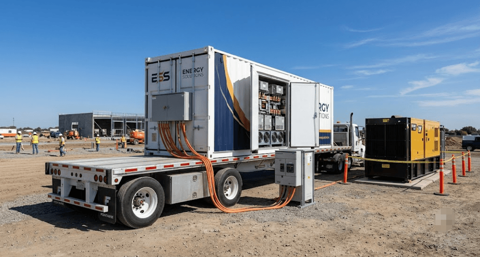
Mobile BESS units are trailer-mounted or containerised storage systems that travel between sites. Common applications include event venues, construction sites, disaster relief operations, emergency grid backup, and temporary peak demand support. Unlike fixed installations, however, mobile BESS PCS units must prioritise three things above all else: portability, ruggedness, and speed of deployment.
Mobile BESS units must reach full power output within hours of arriving on site — which demands a compact, rugged PCS with fast commissioning and multi-source compatibility.
Compact Design and High Power Density
Above all, a mobile BESS PCS must fit inside a trailer or small container. For this reason, power density is the primary design constraint — and liquid-cooled PCS units are preferred above 200 kW because they deliver more power per cubic metre and generate significantly less noise than air-cooled equivalents. Additionally, the PCS must tolerate vibration and shock loads during road transport, which standard stationary units are simply not designed to handle.
Rapid Site Commissioning
Speed of deployment is what sets mobile BESS apart from every other application type. A mobile BESS must reach full power output within a few hours of arriving on site — not the multi-week integration process typical of a permanent installation. Therefore, the PCS must support plug-and-play commissioning: pre-configured protection settings, automatic detection of local grid frequency (50 Hz or 60 Hz), and simple plug-in connections for power and communications.
Furthermore, the PCS must support multiple connection scenarios out of the box — temporary grid connection, islanded operation with a genset, or fully standalone off-grid mode. Consequently, mobile PCS units must include both grid-following and grid-forming capabilities as standard. Waiting for a firmware upgrade or specialist configuration on-site defeats the purpose of a mobile system.
Genset Integration and Overload Capability
Mobile BESS units frequently operate alongside diesel generators. Therefore, the PCS must synchronise with the genset smoothly and manage load transfers in both directions — when the engine starts and when it shuts down. Additionally, overload capability is a hard requirement for mobile deployments. Motor start loads on construction sites or industrial events can draw 150–200% of steady-state current for several seconds. A PCS that trips under this load makes itself useless.
Rugged Enclosure and Wide Temperature Range
Mobile BESS units deploy in unpredictable environments — muddy construction sites, outdoor festivals, flood-affected areas, and extreme climates. Consequently, the PCS must carry an IP55 or higher enclosure rating to resist dust and water ingress. Furthermore, the operating temperature window must extend well beyond typical stationary limits — many mobile PCS products are rated for operation between -25°C and +55°C and storage down to -40°C.
Mobile BESS PCS Key Specifications
Design: Compact, high power density; liquid cooling preferred above 200 kW
Transport Tolerance: Rated for road vibration and shock per IEC 60068-2
Commissioning Time: < 4 hours from arrival to full power output
Grid Frequency Auto-Detect: 50 Hz / 60 Hz without manual reconfiguration
Operating Modes: Grid-following and grid-forming built in as standard
Genset Sync: Smooth synchronisation and load transfer in both directions
Overload: 150–200% rated current for 10 s minimum
Enclosure: IP55 minimum; IP65 for harsh environments
Temperature Range: -25°C to +55°C operating; -40°C storage
PCS Functions Common to All Four Application Types
While each application type has unique demands, several PCS functions are universal. These baseline capabilities define what a PCS is — regardless of where it is installed or what grid code applies.
Bidirectional DC-AC Power Conversion
Every BESS PCS converts DC to AC during discharge and AC to DC during charging. Modern units reach peak conversion efficiency of 96% to 98.5%. However, round-trip efficiency matters more than peak figures. As Sunlith’s energy storage losses guide explains, power conversion is one of the four main loss categories in any BESS. Even a 1% PCS efficiency improvement compounds significantly across a 15-year project life — so it is worth specifying carefully.
BMS and EMS Communication
Two control layers interface with the PCS. Working from the bottom up: the Battery Management System (BMS) sends real-time charge and discharge limits — maximum current, minimum cell voltage, and thermal boundaries. These limits must always be respected by the PCS, including during high-priority grid response events. Above the BMS sits the Energy Management System (EMS), which sends power setpoints and operating mode commands to the PCS.
As Sunlith’s BESS communication protocols guide explains, the BMS transmits SOC, SOH, cell voltages, temperatures, current, and fault codes to enable safe and optimised dispatch. Consequently, the PCS-BMS-EMS communication stack is not merely a data link — it is a safety-critical control interface that must be validated end-to-end before commissioning.
DC-Side Battery Protection
Regardless of application type, all BESS PCS units must protect the DC bus from electrical faults. Key protection functions include over-current limiting, overvoltage protection and DC bus voltage regulation, pre-charge control to prevent capacitor inrush, earth fault detection, and short-circuit protection. Together, these functions protect the battery cells and reduce the risk of thermal runaway events. Therefore, buyers should always request the full DC protection relay specification — not just the AC circuit breaker ratings.
Key Technical Features to Specify in Any BESS PCS
Regardless of application type, the parameters below form a baseline specification checklist for any BESS PCS request for proposal (RFP).
Feature
Typical Range
Notes
Rated Power
30 kW – 10 MW per unit
Confirm continuous rating — not peak or 30-second duty
DC Voltage Range
600 V – 1,500 V DC
Must cover full battery SOC range without derating
AC Output Voltage
400 V / 690 V / 11 kV
MV output reduces transformer count at utility scale
Peak Efficiency
97% – 98.5%
Also request weighted average at your load profile
Power Factor Range
0.8 lead – 0.8 lag
Confirm Q capability at zero kW active output
FFR Response Time
< 100 – 200 ms
Verify against grid code at interconnection point
Grid-Forming Mode
Mandatory (microgrid)
Optional at utility scale; essential for off-grid
Seamless Transfer
< 20 ms C&I; < 10 ms off-grid
Test at FAT — do not accept a datasheet figure only
Communications
Modbus TCP / IEC 61850
IEC 61850 GOOSE for FFR; Modbus TCP for C&I dispatch
Certifications
IEEE 1547, UL 1741-SA, EN 50549
Request current certificates with expiry dates
Cooling
Forced air / Liquid-cooled
Liquid cooling preferred above 500 kW
Enclosure Rating
IP54 indoor; IP55+ outdoor
IP65 for mobile or harsh-environment sites
Warranty
5 – 10 years
Align with BESS project life of 15–20 years minimum
Relevant Standards for BESS PCS
Standards differ by region and application type. Always verify that certifications are current, geographically valid, and cover the specific grid code version in force at your interconnection point. Furthermore, check expiry dates — expired certifications are a common and avoidable cause of project delays.
Use this checklist when writing a BESS PCS request for proposal (RFP). Start with the application type — it determines which items below are mandatory.
Define application type: C&I, utility, microgrid, or mobile. This single decision shapes every other requirement.
Rated Power: Specify continuous AC output (kW) and DC input separately — not peak ratings.
DC Voltage Window: Confirm the PCS operates across the full battery SOC range without derating at either end.
Efficiency Curve: Request weighted average efficiency at your typical daily load profile, not only the nameplate peak value.
Grid-Forming Mode: Mandatory for microgrid. Specify if needed for weak-grid or mobile deployments.
Seamless Transfer Time: < 20 ms for C&I; < 10 ms for off-grid critical loads. Test at FAT without exception.
FFR Response Time: Define maximum latency from EMS setpoint to output ramp start — applicable to utility scale only.
Reactive Power: Specify power factor range. Confirm Q control works at zero kW active power output.
Black Start: Specify explicitly if required — not included in all PCS products. Test on-site.
Overload Capability: 150–200% rated current for 10 s — mandatory for microgrid and mobile types.
Commissioning Time: < 4 hours from arrival to full output — applicable to mobile BESS deployments.
Communications: Specify Modbus TCP, IEC 61850 GOOSE, or CAN Bus as required for your application.
Certifications: List required standards by jurisdiction. Request current certificates with expiry dates.
Enclosure Rating: IP54 for indoor; IP55+ for outdoor; IP65 for mobile or harsh-environment sites.
Inside a battery energy storage system, the Power Conversion System converts DC electricity from the battery to AC for loads or the grid. During charging, it reverses and converts AC to DC. Beyond this basic function, it also controls reactive power, responds to grid frequency and voltage events, and protects the battery. In off-grid systems, furthermore, it synthesises the local AC voltage and frequency reference from battery power alone.
Are C&I and utility scale BESS PCS units the same product?
No — they are significantly different. A C&I PCS focuses on peak shaving, load shifting, solar integration, and fast backup transfer. A utility-scale PCS, by contrast, must meet strict grid code requirements for FFR, reactive power control, and voltage ride-through. Consequently, you cannot simply scale up a C&I PCS for a utility project — the control architecture, communications, and certification requirements are fundamentally different.
Does an off-grid microgrid need a different PCS?
Yes, absolutely. A microgrid BESS PCS must operate in grid-forming mode — synthesising the local AC voltage and frequency without any external grid connection. In addition, it must support black start, droop control, load following, and genset synchronisation. None of these are required in most grid-connected applications. Therefore, always specify off-grid requirements explicitly in procurement documents — do not assume they are included.
What makes a mobile BESS PCS different from a fixed installation?
A mobile BESS PCS must be compact, transport-rated, and fast to commission on arrival. It must auto-detect local grid frequency and support both grid-following and grid-forming modes as standard. Furthermore, it must tolerate road vibration, wide temperature ranges, and variable site conditions that a stationary unit would never encounter. Consequently, mobile PCS units are a distinct product category — not simply a stationary PCS mounted on a trailer.
What efficiency should I expect from a BESS PCS?
Modern BESS PCS units reach peak efficiency of 97% to 98.5%. However, weighted average efficiency across a typical daily profile runs 1–2% lower than the peak figure. Therefore, always request the weighted average efficiency for your specific load profile — the nameplate peak value alone is not a reliable basis for energy yield calculations.
Which standards does a BESS PCS need?
Certification requirements depend on your project location and application type. In the US, IEEE 1547-2018 and UL 1741-SA are typically required. Meanwhile, Europe relies on the EN 50549 standard. For projects in Australia, AS/NZS 4777 is mandatory. Additionally, utility-scale projects in North America must meet NERC CIP cybersecurity requirements. See Sunlith’s Worldwide PCS Certification Guide for full details by country.
How Sunlith Energy Approaches BESS PCS Selection
At Sunlith Energy, we treat the PCS as one of the most important decisions in any energy storage project. Every engagement begins with an application analysis that defines the required operating modes, protection settings, and grid code obligations for that specific site. Furthermore, we verify certifications independently — rather than accepting vendor declarations without review.
Our team has evaluated PCS products across C&I, utility, microgrid, and mobile deployments. Importantly, we carry out PCS-EMS-BMS integration testing before any system leaves the factory. This ensures that communication protocols, protection coordination, and control modes are all validated end-to-end. Consequently, our clients avoid the costly commissioning surprises that arise when integration is left to the site team.
Contact the Sunlith Energy team if your project needs a BESS PCS specification review, vendor proposal evaluation, or commissioning support.
Selecting the right BESS PCS comes down to knowing your application. A C&I system needs peak shaving, backup transfer, and solar integration. A utility-scale project demands FFR, reactive power control, and full grid code compliance. An off-grid microgrid requires grid-forming mode, black start, and droop control. A mobile BESS, moreover, needs ruggedness, fast commissioning, and multi-mode operation out of the box. Therefore, there is no single PCS specification that fits all four scenarios — and trying to use one is a recipe for expensive rework.
Consequently, the first and most important step is to define your application type precisely. From there, use the master comparison table and specification checklists in this guide to build your PCS requirements. Furthermore, involve your PCS vendor early, verify certifications independently, and test all critical functions — especially seamless transfer, black start, and FFR — during factory acceptance testing before the system ships.
Sunlith Energy works with EPCs, project developers, and asset owners across all four BESS application types. Contact our team to discuss PCS requirements for your next project.