A short circuit on the grid side of a BESS behaves nothing like one on the DC bus. IEC 60909 is the standard engineers use to calculate that AC-side fault current.
It also sizes the breakers, relays, and busbars on the grid-facing side of the system.
Quick Answer IEC 60909 is the IEC standard for calculating short-circuit currents in three-phase AC systems. Its current edition, IEC 60909-0:2016, added rules for how inverter-connected sources like BESS and solar contribute to a fault. So this update matters directly for grid-interconnection and protection-coordination studies.
What Is IEC 60909?
The standard covers short-circuit current calculation in three-phase AC systems, both low-voltage and high-voltage. IEC Technical Committee 73 develops it, and that’s a detail worth knowing.
That’s the same committee behind IEC 61660, the DC-side equivalent for auxiliary systems. So the two standards share a family resemblance, and not by accident.
The current edition, IEC 60909-0:2016, replaced a 2001 first edition. It’s a full technical revision, not just a minor tweak.
First, the method places an equivalent voltage source at the fault location. Engineers then work out the fault current from that source. They add the impedance of every AC component between it and the fault point.
IEC 60909’s Maximum and Minimum Short-Circuit Current
Like IEC 61660, IEC 60909 calls for two separate calculations, not one. First, the maximum short-circuit current sets equipment ratings.
The minimum short-circuit current does something different. It sets fuse and relay ratings, and it also checks whether protection will trip fast enough during a fault.
Each case runs on its own assumptions, since network configuration and available sources both shift the result.
How IEC 60909 Models Fault Current Sources
IEC 60909 walks through nearly every source type on an AC system. That list covers network feeders, transformers, overhead lines and cables, synchronous generators, and asynchronous motors.
Each source then gets its own impedance model and its own share of the total fault current.
A network feeder is modeled first, using the utility’s own maximum and minimum short-circuit power at the connection point.
Then transformers, cables, and lines each add their own resistance and reactance in series. This works outward from that feeder toward the fault.
Traditional generation still dominates most of this picture. First, a synchronous generator can feed many times its rated current into a nearby fault.
That’s because the fault current is limited mainly by the machine’s own internal reactance, not by any active control.
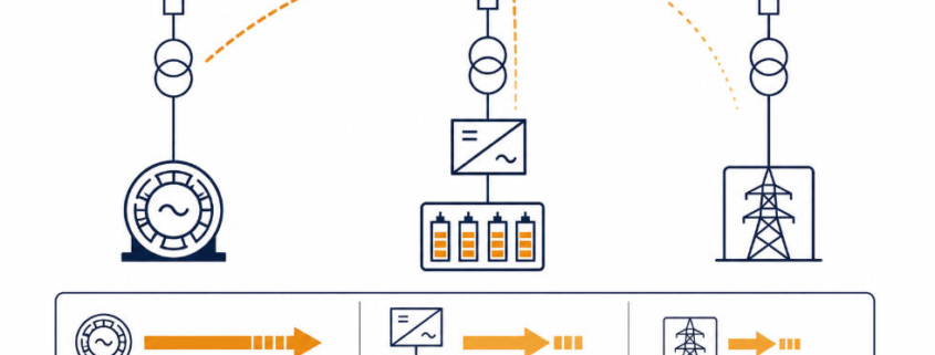
Picture a substation fed by a large synchronous generator on one side and a smaller BESS on the other. A fault right at the busbar draws heavily from the generator, since its current is bounded only by internal reactance.
The BESS contributes too, but through a very different mechanism, covered next.
Asynchronous motors matter here too, since they aren’t purely passive. Large motors briefly feed current back into a nearby fault as they slow down. So the standard includes a separate check for whether that contribution is large enough to count.
Why the 2016 Edition of IEC 60909 Matters for BESS
IEC 60909’s 2016 edition made a genuinely significant change. It added explicit rules for wind power station units and for power station units with full-size converters. Neither type existed in any meaningful way when the 2001 edition published.
A BESS, meanwhile, connects to the grid through exactly this kind of full-size converter: the PCS. So this update is what actually lets engineers model a BESS’s AC-side fault contribution under a current, recognized standard.
Before 2016, engineers had to adapt rules meant for generators instead, which is a poor fit for how a PCS actually behaves.
How a BESS Contributes to an AC Fault
#image_title
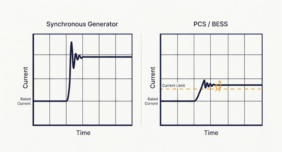
A synchronous generator’s fault current is set by its impedance, not by any active control loop, while a PCS works on a different principle entirely. It behaves very differently.
Since the PCS is a power-electronic device, its control system actively regulates the fault current it can push out. IEC 60909 treats it as a current-regulated source instead of an impedance-limited one.
So that current stays capped close to the converter’s own rated current. It doesn’t spike the way a generator’s current can, because the control loop won’t let it.
What This Means for Protection Coordination
This distinction then has real consequences for a project. A feeder fed mostly by BESS and solar can produce far less fault current. That’s true even compared with the same feeder fed by traditional generation.
Many protection schemes were designed around large, generator-driven fault currents. So a low-fault-current feeder can be harder to detect and clear quickly. Under-reach becomes a real risk once the fault current gets close to normal load current.
IEC 60909-0:2016 gives engineers a standards-based way to calculate that lower contribution accurately. That’s a real improvement over guessing at it or borrowing a generator-based rule of thumb.
It’s also why relay settings tuned for a generator-heavy feeder often need a fresh look once a BESS joins the mix.
IEC 60909 vs. Related Standards
IEC 60909 doesn’t work alone on a BESS project. But a few related standards cover adjacent ground.
Standard
Relationship to IEC 60909
IEC 61660
The DC-side equivalent, covering short-circuit currents in DC auxiliary systems instead of the AC side. Both standards come from the same technical committee.
IEC 62933-5-2
The BESS safety standard, which addresses electrical safety more broadly rather than fault-current calculation methodology specifically.
IEEE 2800-2022
A newer, US-focused standard for interconnecting inverter-based resources, covering performance requirements alongside fault behavior.
The IEC 61660 connection is worth calling out directly. A full BESS fault study often needs both — this standard for the grid-facing AC side, and IEC 61660 for the battery-facing DC side.
What This Means for BESS Grid-Interconnection Studies
For a project engineer, IEC 60909-0:2016 is the tool for AC-side protection coordination and utility interconnection studies. First, model the PCS as a current-regulated source, not a synchronous one.
A BESS project often sits on a feeder alongside other inverter-based generation, like solar. So check the combined fault contribution rather than treating each source alone. Utilities reviewing an interconnection application will still expect exactly this kind of AC-side study.
Frequently Asked Questions
Does IEC 60909 apply to battery energy storage systems?
Yes, through its current edition. IEC 60909-0:2016 added specific rules for power station units with full-size converters, covering how a BESS’s PCS contributes to an AC-side fault.
What’s the difference between IEC 60909 and IEC 61660?
This standard calculates short-circuit currents on the AC side of a system. IEC 61660 covers the DC side instead, such as the battery and busbar side of a BESS.
Why does a BESS contribute less fault current than a generator?
A PCS is a current-regulated power-electronic source, not an impedance-limited one. Its control system caps the fault current close to its own rated current, unlike a synchronous generator.
Is IEC 60909-0:2016 the current edition?
Yes. It replaced the 2001 first edition and remains the standard’s current edition as of 2026.
Who uses IEC 60909 on a BESS project?
Protection engineers and utility interconnection teams use it for AC-side fault current, breaker and relay sizing, and protection coordination studies.
LVRT and HVRT are the two grid rules that keep BESS and solar inverters online during a short voltage sag or spike, instead of letting them shut off and add to a larger grid failure.
Quick Answer LVRT (Low Voltage Ride Through) and HVRT (High Voltage Ride Through) are grid-code requirements that require inverters on BESS and solar plants to remain connected and support the grid during short voltage sags and swells. Under LVRT, inverters must stay online and typically inject reactive current when voltage dips, often down to about 0–0.5 per unit for a few hundred milliseconds to a few seconds, depending on the standard and DER category. Under HVRT, they must tolerate overvoltage, often up to about 1.2–1.3 per unit, and may absorb reactive power. In the US, these rules are defined mainly by IEEE 1547-2018 for distribution-connected DER and IEEE 2800-2022 for transmission-connected plants. The result is that inverters do not trip immediately during faults; instead, they ride through the event within a defined mandatory operating region and only disconnect if voltage moves outside that envelope.
This guide explains what the terms mean, why they exist, and how BESS developers can meet them.
What LVRT and HVRT Mean
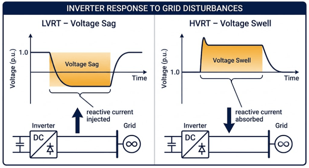
Voltage ride-through means an inverter stays online through a short grid event. LVRT covers sags, when voltage drops below normal. HVRT covers swells, when voltage rises above normal. Faults, lightning, switching, and sudden load shifts can all cause these events.
Older rules worked the other way. Under IEEE 1547-2003, inverters tripped off the moment voltage moved outside a narrow band. A National Renewable Energy Laboratory review calls this “sensitive voltage tripping.” That rule was fine when solar made up a tiny share of power. However, it became a problem once solar and storage grew large. At that scale, one fault could knock out a big share of regional power in seconds.
Why LVRT and HVRT Matter More for BESS
A battery system feels both sides of this problem more than solar alone. During a sag, a BESS can discharge to help voltage recover. During a swell, it can charge to soak up the extra energy. Because of this two-way skill, LVRT and HVRT rules shape how much a storage asset can help, not just how well it survives.
Why LVRT and HVRT Became Mandatory
Grid operators did not add these rules for fun. Instead, they added them after real failures. On August 16, 2016, the Blue Cut Fire in Southern California triggered a transmission fault that knocked out about 1,178 MW of solar PV output, per a NERC/WECC disturbance report. On October 9, 2017, the Canyon 2 Fire caused a separate set of faults that cut roughly 900 MW of solar PV output, per a second NERC disturbance report. In both cases, inverters shut off during brief voltage dips instead of riding through them.
Those failures changed the rules. Now, most DER must stay connected through defined voltage swings. It must also help the grid during that time. As a result, ride-through moved from a nice-to-have feature to a hard certification requirement.
Balancing Worker Safety With Grid Stability
Utilities still need inverters to trip for real faults on their own lines. This is because a downed line stays dangerous to line workers if power keeps flowing. Grid codes solve this with clear voltage-and-time limits. Inside the limit, the plant must ride through. Outside it, tripping is allowed. That line is the whole point of an LVRT and HVRT curve.
How Ride-Through Curves Work
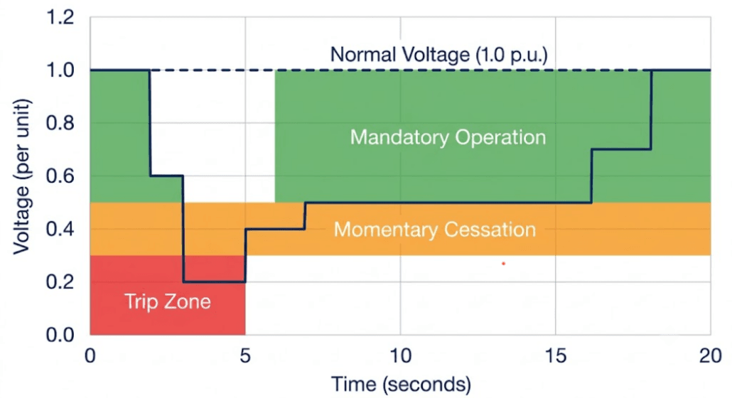
Every LVRT and HVRT rule is drawn as a curve. The curve plots voltage against time. A voltage of 1.0 p.u. is normal. A voltage of 0.0 p.u. is a dead short at the terminals. For each voltage level, the curve sets the shortest time an inverter must stay connected.
Mandatory Operation, Momentary Cessation, and Trip
IEEE 1547-2018 names three responses inside this curve. First, mandatory operation. The inverter must keep sending active and reactive current as set by the rule. Second, momentary cessation. The inverter can pause briefly, usually below 0.5 p.u., then restart fast once voltage returns. Third, trip. This is only allowed once the event falls outside both zones. Meanwhile, IEEE 2800-2022, the newer rule for large plants, limits momentary cessation even further. That pause behavior helped cause the California events.
Reactive Current Injection Under LVRT and HVRT
Modern codes ask for more than staying online. During a sag, the inverter must push extra reactive current to help raise local voltage. During a swell, it pulls reactive current to help bring voltage back down. This response is set by a gain value, called a k-factor. Most codes set k between 2 and 6. As a result, a bigger sag gets a bigger response, up to the inverter’s current limit.
IEEE 1547-2018 and IEEE 2800-2022: The US Framework
In the US, smaller grid-connected systems follow IEEE 1547-2018. Meanwhile, large, transmission-connected plants follow IEEE 2800-2022. Both set clear LVRT and HVRT rules. NERC PRC-024 sets outer voltage and frequency limits. Therefore, no bulk-system plant may trip inside those limits. It acts as a backstop for both standards.
DER Categories and LVRT and HVRT Coverage
IEEE 1547-2018 splits inverters into three groups. Each group has its own ride-through table.
Category
Typical Use Case
Ride-Through Behavior
Category I
Legacy, minimal support
Narrowest band, simple and low-cost
Category II
Moderate DER growth
Wider band, some pause allowed at low voltage
Category III
High-growth areas, utility-scale BESS and solar
Widest band, longest hold time, built for grid reliability
A utility or public commission picks the category for each project. Today, most utility-scale BESS projects use Category III. That is because it gives the longest ride-through time and the most grid support.
Global LVRT and HVRT Codes Compared
Exact limits shift by country. The core idea stays the same everywhere. In the US row below, remember that IEEE 2800-2022 applies specifically to transmission-connected plants, not smaller distribution-tied systems.
The same distribution-versus-transmission split applies to Europe — EN 50549-1 governs smaller distribution-connected plants, while ENTSO-E RfG governs transmission-connected ones, similar to the US split between IEEE 1547-2018 and IEEE 2800-2022.
Region
Governing Code
Representative LVRT/HVRT Envelope
United States (distribution)
IEEE 1547-2018
Ride through down to 0.0-0.5 p.u. for up to several hundred milliseconds, by category
United States (transmission, ERCOT)
IEEE 2800-2022, ERCOT NOG
Legacy and voltage-dip profiles, tested via Model Quality Test
Great Britain
National Grid ESO Grid Code (CC.6.3.15)
Active power recovery within 0.5s for faults cleared in ≤140ms, or within 1s for longer faults
Germany
VDE-AR-N 4110 (MV) / 4120 (HV)
Fault current must start within about 30 milliseconds
Europe (LV/MV distribution)
EN 50549-1
Must stay operational down to 0.8 p.u.; resumes at least 90% of pre-fault power within 1s of voltage recovery
European Union (transmission)
ENTSO-E RfG (Regulation 2016/631)
Minimum zero-voltage ride-through period of ~150ms for Type C/D generating modules; local rollout of shared profiles, tested per FGW TR3 or similar
Germany and the EU tend to demand a faster fault-current response than the US baseline. Their grids already carry more inverter-based power, so the margin for delay is smaller. ERCOT asks for two test profiles from both BESS and solar: a legacy dip and a step-by-step voltage-dip curve. Because of this, a plant controller must line up the reactive response from every inverter at one shared point.
For a country-by-country overview of BESS interconnection requirements—including US, EU, UK, Australia, and India frameworks—see our BESS grid codes and compliance guide.
Why Project-Specific Studies Still Matter
A generic grid-code curve sets the floor. However, it is not the final word. The interconnection study for one project can tighten that curve. Specifically, it looks at local grid strength, fault current, and protection settings. For that reason, developers should treat the study, not the general code, as the rule that governs a live project.
LVRT vs. HVRT: Key Differences
LVRT and HVRT share one framework. They differ in cause and response.
Trigger: LVRT reacts to sags from faults or heavy switching. HVRT reacts to swells, often from sudden load loss or capacitor switching.
Reactive response: LVRT asks for pushed current to raise voltage. HVRT asks for pulled current to lower it.
Typical severity: LVRT events tend to run deeper and happen more often. Short circuits are simply more common than large load losses.
BESS behavior: A BESS can discharge to help LVRT and charge to help HVRT. A solar-only plant cannot do both.
How BESS Inverters Achieve LVRT and HVRT Compliance
Meeting a curve on paper is easy. Meeting it in the field, under a real fault, depends on how the inverter is built.
Grid-Following vs. Grid-Forming Response
Most inverters today are grid-following. They read grid voltage and frequency through a phase-locked loop, then respond with current. Grid-following units can meet LVRT and HVRT rules. However, their speed is capped by how fast that loop can track a distorted wave during a fault. Grid-forming inverters work differently. Instead, they set their own voltage reference, which gives a faster LVRT and HVRT response. They act more like a spinning generator. Increasingly, more grid codes now favor this design in high-growth areas.
Reactive Current Priority and Current Limits
During a deep sag, an inverter’s total current is capped by its hardware. So, the control system must split that limited current between active power and reactive support. Most codes put reactive current first, since it does the most to fix voltage. Any leftover current then goes to active power. Getting this order wrong is a common reason inverters fail a compliance test, even when the timing is correct.
Testing and Certification
LVRT and HVRT compliance is tested, not assumed. In the US, UL 1741 certification checks baseline inverter behavior. Meanwhile, large projects also need project-specific Model Quality Testing. ERCOT now requires this test for both solar and BESS plants.
What Model Quality Testing Covers
This test runs the full LVRT and HVRT curve under controlled conditions. It starts with a flat-start check and a small voltage test. Next comes LVRT testing under both a legacy curve and a voltage-dip curve. HVRT testing follows the same pattern. Other tests check small frequency shifts during charge and discharge, and grid strength across several fault levels. Finally, a phase-angle-jump test, run in software like PSCAD, closes out the sequence. Importantly, the plant controller is tested with every inverter together, not alone. Otherwise, the combined response at the shared connection point can differ from any single unit’s result.
Design Considerations for LVRT and HVRT Compliance
Treat LVRT and HVRT compliance as a design choice, not a final checklist item.
Confirm the DER category early. The utility’s choice of Category I, II, or III sets both the inverter type and the ride-through curve. This choice is hard to change later.
Size reactive headroom on purpose. Saving current for reactive support cuts the active power on hand during a fault. This shapes how you manage state of charge.
Coordinate the plant controller model. For hybrid solar-plus-storage sites, test the plant controller with every inverter together. Do not test each unit alone.
Track changing standards. IEEE 2800 updates and ERCOT’s guide keep shifting. A BESS built to an old curve may fail today’s interconnection study.
LVRT/HVRT compliance is one part of the broader interconnection pathway. For the full sequence from application and network studies to commissioning and permission to operate, see our BESS interconnection process guide.
Key Takeaways
Point
Why It Matters
LVRT and HVRT keep inverters online during grid events
Stops a single fault from cascading into a large power loss
IEEE 1547-2018 sets three DER categories
Category III applies to most utility-scale BESS today
Reactive current support is required, not optional
A k-factor of 2-6 sets how much support is needed
Grid codes shift by region
Germany and the EU ask for a faster fault response than the US
Compliance is tested, not assumed
UL 1741 and Model Quality Testing both apply
Frequently Asked Questions
What Does LVRT Stand For?
LVRT stands for low-voltage ride-through. It is a grid-code requirement that requires inverters on BESS and solar plants to stay connected and support the grid during short voltage sags. Under LVRT, inverters must typically inject reactive current when voltage dips, often down to about 0–0.5 per unit for a few hundred milliseconds to a few seconds, depending on the standard and DER category. Instead of tripping immediately, inverters ride through the event within a defined mandatory operating region and only disconnect if voltage moves outside that envelope.
What Is the Difference Between LVRT and HVRT?
LVRT deals with low-voltage events, such as faults that cause voltage to drop, while HVRT deals with high-voltage events, such as switching transients or sudden loss of load that cause voltage to rise. Under LVRT, inverters typically inject reactive current to support voltage; under HVRT, they must tolerate overvoltage, often up to about 1.2–1.3 per unit, and may absorb reactive power. Both requirements aim to keep inverters connected during short disturbances instead of tripping and worsening the event.
Is HVRT Required for BESS as Well as Solar?
Yes. Any grid-tied inverter, including battery storage, must generally meet both LVRT and HVRT rules as a condition of interconnection. In the US, IEEE 1547-2018 applies to most distribution-connected DER, and IEEE 2800-2022 applies to transmission-connected plants. Smaller or legacy systems may be governed by older interconnection agreements, but new projects should expect to demonstrate ride-through capability in studies and commissioning tests.
What Happens if an Inverter Fails to Ride Through a Fault?
If an inverter or plant cannot meet LVRT/HVRT requirements, it may trip offline during a fault or system disturbance. Widespread tripping can add to larger power losses, similar to the 2016 and 2017 California solar-loss events that helped drive stricter ride-through rules. Repeated failures or non-compliance can also put a project’s interconnection agreement at risk, leading to export limits, required hardware or control changes, or refusal of permission to operate until the issue is resolved.
How Is LVRT and HVRT Compliance Verified?
Compliance is verified through a combination of product certification and plant-level testing. Individual inverters are typically certified to standards such as UL 1741 (which references IEEE 1547 ride-through curves). For larger plants, system operators often require Model Quality Testing or equivalent studies to confirm that the combined response of all inverters and the plant controller meets the applicable grid code at the point of common coupling. Together, these confirm that the plant controller and every inverter meet the required voltage ride-through curves and reactive current behavior.
Do LVRT and HVRT Requirements Differ Between the US and Europe?
Yes. LVRT and HVRT requirements vary by country, region, and connection voltage. The US uses IEEE 1547-2018 for distribution-connected DER and IEEE 2800-2022 for transmission-connected plants. The EU follows the ENTSO-E RfG framework, applied locally through national codes such as Germany’s VDE-AR-N 4110, which often expects faster fault-current response and tighter ride-through behavior than the current US baseline. The general principle—ride through short voltage events and support the grid—is similar, but the exact voltage ranges, time durations, and reactive current requirements differ.
Are LVRT and HVRT Requirements the Same in Every Country?
No. Requirements differ by market and grid code. Beyond the US and Europe, regions such as Australia, India, and others define their own ride-through profiles and testing rules, often tailored to local network conditions. Developers should always check the applicable distribution or transmission code and the project’s interconnection agreement, rather than assuming a single global LVRT/HVRT standard.
Great Britain (National Grid ESO / NESO Grid Code CC.6.3.15): NESO Grid Code Workshop — Fault Ride Through Background — National Grid ESO has since rebranded to NESO (National Energy System Operator); the old nationalgrid.com URL for this document no longer resolves, so this link has been updated to the current neso.energy address. Confirms the 140ms fault duration threshold and the 0.5s/1s active power restoration windows directly.
EN 50549-1 (0.8 p.u. operational threshold, 90% power resumed within 1s): Intertek EN 50549-1:2019 Test Report (Report No. 210500399TPE-001) — an accredited third-party certification test report, stronger than a preprint. It directly quotes the standard’s requirement text and confirms it against real test data.