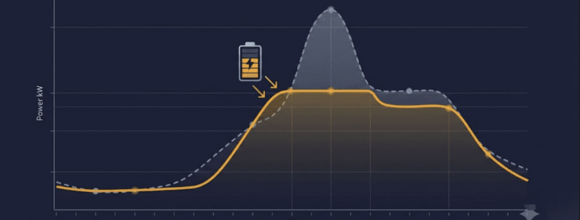
Energy arbitrage is the simplest revenue strategy in battery storage. A battery charges when electricity is cheap. Then, it discharges when electricity is expensive. The gap between those two prices is the spread. Capturing that spread is the entire strategy.
However, the full spread is never pure profit. Efficiency losses shrink it. Battery wear shrinks it further. This guide walks through how the strategy actually earns money, which costs cut into that revenue, and how to calculate the spread a project truly needs. For how this fits alongside other revenue streams, see our C&I BESS economics guide and our peak shaving vs. load shifting comparison.
How the Strategy Works
The pattern repeats daily. First, prices drop overnight, when demand is low. A battery charges during these cheap hours. Then, prices climb during the day. They often peak on hot afternoons, when air conditioning load surges. As a result, the battery discharges during these expensive hours, selling stored energy back at the higher rate.
Market structure shapes how much a project can actually earn. Deregulated markets tend to see more price swings, and those swings are what create opportunity in the first place. Grid congestion adds a second layer of upside. When transmission lines hit their limits, prices can vary sharply by location. So, a battery placed in the right zone can capture that gap too, on top of the daily time-based one.
Three Hidden Costs That Cut Into Your Margin
A visible price gap doesn’t automatically mean a profitable trade. Three factors quietly shrink that spread before it becomes real revenue.
Round-trip efficienc:. No battery returns 100% of the electricity it stores. Lithium-ion systems typically land in the 83–92% range, depending on chemistry, C-rate, and cooling. In other words, 10 kWh charged in might only return 8.5–9.2 kWh usable. Because of this, the sell price has to clear the buy price by more than the visible gap suggests — not just match it.
Battery degradation: Each cycle wears the battery down a little. In fact, one widely cited analysis of MISO market data found that degradation cut arbitrage revenue by roughly 12–46%, depending on the model used. This is easy to overlook, since it’s tempting to model efficiency losses and stop there.
Market fees and upkeep: Wholesale trading usually carries transaction fees. Meanwhile, the storage system itself needs ongoing maintenance. Both come out of the spread before any of it reaches the bottom line.
Put together, these three costs mean the sticker-price spread overstates the real opportunity. So, a strategy needs enough room to absorb all three and still turn a profit.
Calculating the Spread You Actually Need
Think of this as your breakeven point — the minimum price gap before the strategy is worth pursuing. Here’s the formula:
Here’s how that plays out in a simple, illustrative example:
Metric
Value
Off-peak charging cost
$25/MWh
Round-trip efficiency
88%
Effective charging cost
$25 ÷ 0.88 = $28.40/MWh
Degradation cost per cycle (illustrative)
$4/MWh
O&M and market fee allocation (illustrative)
$2/MWh
Breakeven discharge price
$28.40 + $4 + $2 = $34.40/MWh
In this example, the battery needs to sell above $34.40/MWh just to break even. That’s well above the $25/MWh most people assume is the real bar. Anything captured beyond that line becomes genuine margin. This is exactly why a headline spread can look attractive on paper, yet still produce thin or negative returns in practice.
What Actually Moves the Market
Price volatility: The wider and more frequent the daily swings, the more spread there is to capture. Flat, low-volatility tariffs, on the other hand, produce little to no opportunity.
Market structure: Deregulated wholesale markets generally offer more trading opportunity than fixed-tariff regulated ones.
Renewable penetration: Heavy solar and wind generation can trigger fast, large price swings — sometimes even negative prices during oversupply — which widens the gap available to a well-positioned battery.
Locational congestion: Grid bottlenecks create price differences between zones. Therefore, batteries sited near congestion points can capture that gap too, in addition to the daily one.
Analysts commonly benchmark this opportunity using “top-bottom” (TB) spreads — the gap between a market’s highest- and lowest-priced hours — as a standard way to compare potential across regions and durations. For broader market cost trends, the EIA’s battery storage market analysis is a useful reference point.
Why Most Projects Don’t Rely on This Alone
In practice, few BESS projects lean on a single revenue stream. Instead, layering in demand charge reduction, frequency regulation, or capacity payments spreads risk across multiple sources. As a result, this generally improves overall project economics compared to going it alone. See our peak shaving savings breakdown for how demand charge reduction stacks alongside this strategy, or our BESS cost per kWh and LCOS guide for the full project economics picture.
Merchant projects — ones relying entirely on wholesale price spreads with no fixed contract — carry real risk. Revenue depends on spreads that can shrink if market conditions or rules change. Contracted revenue, or a blended approach, generally reduces that exposure.
Energy Arbitrage Frequently Asked Questions
What is energy arbitrage in battery storage?
Energy arbitrage is the practice of charging a battery when electricity prices are low and discharging it when prices are high, capturing the price difference as revenue.
How much does round-trip efficiency affect energy arbitrage revenue?
Lithium-ion systems typically operate at 83–92% round-trip efficiency. That lost 8–17% means the discharge price must clear the charging cost by more than the visible spread suggests, not just match it.
Does battery degradation really cut into arbitrage profits?
Yes, substantially. Research using historical MISO market data found degradation reduced arbitrage revenue by roughly 12–46%, depending on the degradation model used. It’s one of the most commonly underestimated costs in arbitrage economics.
Is energy arbitrage alone enough to justify a BESS project?
Rarely as a standalone strategy. Most successful projects stack energy arbitrage with demand charge reduction, frequency regulation, or capacity payments to diversify revenue and improve overall project economics.
Next Steps
Ready to model your own numbers? Start with your local wholesale or time-of-use price spread. Then, apply the breakeven formula above, and compare it against your battery’s round-trip efficiency and degradation curve. For the full system cost picture, see our BESS cost per kWh and LCOS guide, or explore how this strategy stacks with other revenue streams in our C&I BESS economics guide.
In this guide, we will explain everything in a simple and easy-to-understand way.
🔍 What Are TOPCon Solar Cells?
TOPCon stands for Tunnel Oxide Passivated Contact. It is a new type of solar cell that increases power generation by reducing energy loss.
These solar cells use a special design that helps move electricity more smoothly. This means you get more energy from the same amount of sunlight.
Unlike older types of cells, TOPCon solar cells use n-type silicon, which does not degrade as fast and works better in all weather conditions.
🧱 How TOPCon Solar Cells Are Built
Here’s how the structure of a TOPCon solar cell looks:
Layer
Function
N-type Silicon Wafer
Main base of the cell, long-lasting
Tunnel Oxide Layer
Ultra-thin layer to stop energy loss
Polycrystalline Silicon Layer
Helps carry electricity smoothly
Anti-Reflective Coating
Catches more sunlight
Metal Contacts
Transfers electricity to the system
Thanks to this advanced structure, TOPCon solar cells can deliver better results than regular monocrystalline or PERC cells.
⚙️ How Do TOPCon Solar Cells Work?
Solar cells work by changing sunlight into electricity. But some of that energy gets lost along the way.
TOPCon cells solve this problem by using a very thin oxide layer and a special contact layer. This combo helps electrons move faster without getting lost.
Here’s a simple explanation:
Sunlight hits the cell.
Electrons are created.
These electrons move through the tunnel oxide.
The special contact layer helps collect them.
Electricity is sent to your home or battery.
Because there’s less waste, TOPCon solar cells are more efficient.
📈 Efficiency of TOPCon Solar Cells
One of the biggest reasons people are excited about TOPCon technology is its high efficiency.
TOPCon panels can reach 22% to 23.5% efficiency.
Standard panels like polycrystalline reach only 15%–17%.
Monocrystalline and PERC usually reach 18%–21%.
That means with TOPCon, you get more power using the same space.
🔄 TOPCon vs PERC vs Other Solar Cells
Let’s look at how TOPCon solar cells compare to other common technologies:
Feature
Polycrystalline
Monocrystalline
PERC
TOPCon
Silicon Type
P-type
P-type
P-type
N-type
Efficiency Range
15%–17%
18%–20%
20%–21.5%
22%–23.5%
Degradation Rate
Higher
Medium
Medium
Very Low
Low-Light Performance
Poor
Average
Good
Excellent
Cost
Low
Medium
Medium
Slightly High
Lifespan
20–25 years
25–30 years
25–30 years
30+ years
As you can see, TOPCon solar cells are one of the best in almost every category.
✅ Key Benefits of TOPCon Solar Cells
Here are the top reasons why more people are choosing TOPCon technology:
1. Higher Energy Output
TOPCon cells are more efficient. You get more power per panel.
2. Better in Cloudy or Low-Light Conditions
Because of the n-type silicon and advanced design, TOPCon works even when sunlight is not strong.
3. Longer Life and Better Stability
These panels degrade very slowly. That means they keep performing well for more years.
4. Lower Temperature Loss
In hot weather, normal panels lose efficiency. TOPCon handles heat better, so you don’t lose as much energy.
5. Bifacial Ready
Many TOPCon panels are bifacial, which means they generate electricity from both the front and the back side. That adds even more power!
❌ Are There Any Drawbacks?
Even though TOPCon is amazing, it’s not perfect.
Here are some minor drawbacks:
Slightly Higher Price – Because of the advanced structure, TOPCon costs more than regular panels.
Newer Technology – Not all installers are familiar with it yet.
More Precise Manufacturing Needed – It takes better equipment and control to make these cells.
Still, for the performance you get, many believe it’s worth the extra investment.
🌍 Where Can TOPCon Be Used?
TOPCon solar cells are perfect for:
Rooftop solar systems (homes and businesses)
Solar farms and utility-scale projects
Projects where space is limited but high output is needed
Areas with high temperatures or frequent cloudy weather
If you’re planning a long-term project and want high return, TOPCon is a great choice.
🏭 Who Makes TOPCon Panels?
Several major companies have already launched TOPCon-based solar panels:
These manufacturers are expanding their production lines, and prices are slowly becoming more affordable.
🧠 Frequently Asked Questions
🔹 Is TOPCon better than PERC?
Yes, in most ways. It offers more efficiency, better performance in heat and shade, and longer life.
🔹 Does TOPCon cost more?
A little, yes. But the extra power and longer lifespan can make up for that cost over time.
🔹 Is TOPCon good for home solar?
Absolutely! Especially if your roof space is limited and you want to get the most energy per panel.
🚀 Final Thoughts: Is TOPCon the Right Choice for You?
If you care about performance, future value, and reliability, then TOPCon solar cells are a smart pick.
They give you:
More energy
Less loss
Longer life
Better value over time
Yes, the initial price is slightly higher—but the long-term gain is much greater.
TOPCon is not just a technical upgrade—it’s a smarter solar decision.
🔧 Need Help Choosing the Right Solar Panels?
As a sourcing and procurement consultant in the new energy field, I help clients select the best-fit solar technology for their project’s location, budget, and performance needs.
⚡ Key Takeaways • A 100kW load run continuously (24/7) consumes 2,400 kWh per day. That daily energy figure is what drives solar and battery sizing. • Solar array size must be calculated for your worst realistic Peak Sun Hour (PSH) day, not your annual average — winter and cloudy-day sizing can be 2–2.5x larger than summer sizing. • Battery capacity depends on days of autonomy, Depth of Discharge (DoD), and round-trip efficiency — budget 3,000–10,000 kWh depending on backup duration. • The PCS/inverter is frequently undersized in DIY calculations — it must handle both the continuous 100kW draw and any surge/peak load, plus simultaneous charge and discharge in hybrid topologies. • LFP (LiFePO4) cells are the standard choice for stationary systems at this scale, rated for 3,000–5,000+ cycles at 80% DoD.
Planning solar panels and batteries to run a 100kW load around the clock? Sizing this correctly isn’t as simple as multiplying watts by hours, though.
Weather conditions, seasonal sunlight availability, cloudy-day derating, inverter sizing, and battery efficiency losses all factor in. Because of that, this guide walks through the full sizing process step by step, building toward a properly sized battery energy storage system (BESS) with formulas, worked examples, and a free interactive calculator.
📌 What You’ll Learn About Sizing for a 100kW Load
How to calculate required solar panel capacity for a continuous load
Why yearly weather data and Peak Sun Hours are critical to correct sizing
How to handle cloudy days and winter months without under-building
Battery sizing for different backup durations, DoD, and round-trip efficiency
How to size the PCS/inverter — the step most sizing guides skip
Battery chemistry, cycle life, and thermal management considerations at 100kW scale
Rough cost and payback framing so you can budget before requesting quotes
Example formulas and real-world worked values
🔧 Step 1: Understand Your 100kW Load
Let’s start with a 100kW load running 24 hours a day, every day.
100 kW × 24 hours = 2,400 kWh per day
That 2,400 kWh/day figure is your daily energy demand — it’s what solar and battery capacity are sized against.
If your load isn’t perfectly flat — for example, it dips to 60kW overnight and spikes to 130kW during a production shift — use the peak figure for PCS/inverter sizing. Use the daily kWh total instead (from a load profile or utility bill) for solar and battery sizing.
Averaging a variable load into a flat 100kW figure will, in short, undersize your inverter for the actual peak.
🌍 Step 2: Analyze Your Location’s Solar Irradiance for a 100kW Load
Your geographic location heavily influences how much sunlight you receive. Specifically, this is measured in Peak Sun Hours (PSH), the equivalent number of hours per day at 1,000 W/m² irradiance.
Location
Peak Sun Hours (avg)
Phoenix, USA
6.5 PSH
New Delhi, India
5.5 PSH
London, UK
2.8 PSH
👉 You can pull PSH data for your exact site from PVWatts (operated by the National Laboratory of the Rockies, formerly NREL), the NASA POWER Data Access Viewer, or commercial tools like Solcast. For a full breakdown of PSH by region and how it interacts with panel tilt, see our dedicated guides:
Sizing for the worst realistic case (cloudy-day PSH) rather than the annual average is, in fact, the single most common mistake in DIY sizing. In other words, it’s the difference between a system that works on a sunny July afternoon and one that keeps your load running in December.
🌥️ Why Consider Cloudy Days When Sizing a 100kW Load?
Even in a region with high annual irradiance, you’ll still, in fact, face stretches of poor sun exposure. For mission-critical applications, therefore, your system must:
Be oversized for worst-case scenarios, not average-case.
Include battery backup sized for 1–3 days of autonomy.
Use hybrid systems (generators or grid backup) where continuous uptime is non-negotiable.
❄️ Considerations for Winter Months
Winter brings three compounding effects:
Lower sun angles, which reduce effective irradiance on fixed-tilt arrays
Shorter daylight hours, which shrinks your PSH window
Snow cover in northern regions, which can fully block production for days
As a result, effective PSH drops and your dependence on stored energy or supplemental power increases. That’s exactly why the winter row in the Step 3 table above requires roughly 1.6x more solar capacity than the summer row.
⚡ Step 4: Size the Battery Energy Storage System for a 100kW Load
Ultimately, your BESS needs to store enough energy to power the load during non-sunny hours or outright weather/grid failures.
Formula:
Battery Capacity (kWh) = (Daily Load × Days of Autonomy) ÷ (DoD × Efficiency)
Daily Load = 2,400 kWh
Depth of Discharge (DoD) = 0.8
Round-trip Efficiency = 0.9
Backup Duration
Required Battery Capacity
1 Day
2,400 ÷ (0.8 × 0.9) ≈ 3,333 kWh
2 Days
4,800 ÷ (0.8 × 0.9) ≈ 6,667 kWh
3 Days
7,200 ÷ (0.8 × 0.9) ≈ 10,000 kWh
Note that these figures are usable energy requirements — rated (nameplate) capacity will need to be slightly higher once you account for BMS reserve margins and end-of-life capacity fade. For the difference between rated and usable capacity units, see Ah vs Wh Battery Capacity Explained, and for the general framework behind these backup calculations, see our Energy Storage Calculation Guide.
🔌 Step 5: Size the PCS / Inverter for Your 100kW Load (Often the Missing Step)
Solar array and battery capacity get most of the attention in sizing guides. However, the Power Conversion System (PCS) — the bidirectional inverter that moves power between panels, batteries, and load — is just as critical. In fact, it’s the component most DIY calculations undersize.
Specifically, your PCS needs enough continuous rating to handle the load, plus headroom for surge and simultaneous charge/discharge:
Continuous rating: must cover your 100kW continuous draw, not the average of a variable load profile.
Peak/surge rating: motor starts, compressor inrush, and HVAC cycling can spike 20–50% above continuous draw for a few seconds — undersized PCS units trip or clip during these events.
Simultaneous charge + discharge: in a hybrid solar + battery + load topology, the PCS may need to charge the battery from solar while discharging to load at the same time — size for the combined throughput, not just the larger of the two.
As a starting point, a reasonable figure for a 100kW continuous load is a 125–150kW PCS, though the correct number depends on your actual peak load profile and topology. For the functional breakdown of what a PCS does and how to evaluate one, see:
🔋 Battery Chemistry & Cycle Life for a Continuous-Duty 100kW Load
A 100kW load running 24/7 puts a battery through far more charge/discharge cycles per year than a typical backup-only installation. As a result, chemistry and cycle-life ratings matter more here than in a system that only discharges occasionally.
LFP (LiFePO4) is the standard choice for stationary systems at this scale: Tier-1 EV-grade LFP cells are typically rated 3,000–3,500 cycles at 0.5C / 80% DoD, with 120Ah-class prismatic cells often rated 3,500–6,000 cycles.
NMC offers higher energy density but lower cycle life and reduced thermal stability — generally a weaker fit for continuous-duty stationary storage than for space-constrained mobile applications.
Sodium-ion is an emerging alternative worth watching for cost-sensitive, cycle-heavy applications, though it currently trails LFP on energy density.
At 1–2 cycles per day, a 3,500-cycle-rated cell reaches end-of-life capacity (~80% of nameplate) in roughly 5–10 years. Therefore, factor this into both your battery oversizing margin and your long-term budget. For deeper comparisons:
🌡️ Thermal Management: Do You Need Liquid Cooling at This Scale?
A 3,000–10,000 kWh battery bank running near-continuous cycling generates meaningfully more heat than an occasional-backup system of the same size. Consequently, thermal management becomes a real design decision rather than an afterthought.
Air-cooled systems are simpler and cheaper, and remain viable for lower cycle-rate, moderate-climate installations.
Liquid-cooled systems hold tighter cell-to-cell temperature gradients, which matters directly for the cycle-life numbers above — sustained high temperatures accelerate capacity fade regardless of chemistry.
For continuous 0.5C–1C duty cycles in hot climates, liquid cooling is generally the safer long-term choice despite the higher upfront cost.
Install with adjustable tilt for seasonal optimization
TOPCon cells are, in fact, increasingly the default choice for higher-efficiency Tier-1 modules. For more detail, see our TOPCon Solar Cells guide on how they compare to standard PERC panels.
✅ Tips for Choosing Battery Cells for BESS
Use temperature-controlled (or liquid-cooled) enclosures for extreme climates
Choose Lithium Iron Phosphate (LFP) for safety and long cycle life at continuous-duty scale
Look for modular scalability so you can expand storage as load grows
Integrate with a proven BMS and EMS — don’t treat this as an afterthought
🔄 Hybrid Solutions for a Reliable 100kW Load
When powering a 100kW continuous load, therefore, it’s worth considering a hybrid setup:
Go fully off-grid: Solar + Wind + Battery — for redundancy in variable-weather regions
Add diesel backup: Solar + Battery + Diesel — for industrial backup where uptime is non-negotiable
Stay grid-connected: Solar + Grid + Battery — for grid-tied systems using the battery mainly for peak shaving and outage ride-through
💰 Estimating Total System Cost & Payback for a 100kW Load
Before requesting formal quotes, it helps to budget at a rough order of magnitude. Specifically, total installed cost scales with three line items: the solar array (per-watt installed cost), the battery bank (per-kWh installed cost), and the PCS/BOS/engineering package. Typically, the battery bank is the single largest line item at this scale given the 3,000–10,000 kWh range from Step 4.
Get exact per-watt and per-kWh figures from vendor quotes — these vary significantly by region, scale, and financing structure, so we intentionally don’t publish a single blended $/kWh figure here.
Payback period depends heavily on your alternative: offsetting diesel genset fuel and grid demand charges typically pays back faster than pure grid-tied offset in low-electricity-cost regions.
Model your specific numbers rather than relying on rule-of-thumb payback claims.
Battery for 2 days = 2,400 × 2 ÷ (0.8 × 0.9) ≈ 6,667 kWh
PCS sizing (per Step 5): 125–150 kW continuous, sized for the facility’s actual peak/surge profile
While static estimates give you a solid baseline, real-world engineering requires calculating system sizing interactively based on your specific geographical peak sun hours and target safety thresholds.
🧮 Interactive Solar & BESS Capacity Calculator
Use our professional sizing engine below to customize your numbers. Specifically, this tool automatically computes the balance between direct daytime consumption and the excess energy required to charge the battery bank for night or emergency runs.
☀️ Solar & BESS Capacity Calculator
📊 Recommended Sizing Results:
Daily Total Consumption: kWh/day
Required Solar Array Capacity: kWp
Required Battery Storage (BESS): kWh
Minimum Suggested PCS/Inverter: kW
🛠️ Sizing Definitions Explained
Daily Total Consumption (kWh): the total energy your system expends every day.
Required Solar Array Capacity (kWp): the nameplate rating of your panel configuration under Standard Test Conditions (STC), sized high enough to fill your BESS during operating hours.
Required Battery Storage (BESS, kWh): the gross storage capacity needed to survive weather downturns without exceeding safe Depth of Discharge (DoD).
PCS / Inverter Rating (kW): the continuous and surge power-handling capacity of the conversion system linking panels, batteries, and load — see Step 5 above.
📖 Recommended Sizing Resources for a 100kW Load
To fine-tune your inputs for the calculator above, explore our comprehensive technical guides:
Only if your load is flexible or you remain connected to the grid as a backstop. Otherwise, a continuous 100kW load with no grid connection and no battery has zero ride-through the moment the sun sets or a cloud rolls in.
Q: Should I oversize the battery or the solar array?
Both, in proportion to your climate. Specifically, cloudy regions need more solar oversizing to fill the same battery bank in fewer usable hours, while regions with frequent multi-day outages need more battery autonomy regardless of solar oversizing.
Q: What’s better — LFP or NMC batteries?
LFP is generally the safer, longer-cycle-life choice for stationary storage at this scale, while NMC’s higher energy density suits space-constrained mobile applications more than fixed installations.
Q: How big a PCS/inverter do I actually need for a 100kW Load?
Size for your actual peak draw plus surge headroom, rather than the 100kW continuous average. As a starting range, 125–150kW is reasonable, though you should pull your real load profile before finalizing (see Step 5).
Q: Do I need liquid cooling for a battery bank this size?
Not always — it depends on cycling frequency and climate. Continuous 0.5C–1C duty in hot climates benefits meaningfully from liquid cooling’s tighter thermal gradients, while lower cycle-rate systems in moderate climates can often stay air-cooled.
Q: How long will the battery bank last before it needs replacing?
Tier-1 LFP cells at 0.5C/80% DoD are typically rated 3,000–6,000 cycles. At roughly one full cycle per day, that’s a working life in the 8–14-year range before capacity fades to around 80% of nameplate, so budget your replacement schedule accordingly.
Q: Is grid-tied or off-grid better for a 100kW continuous load?
Grid-tied lets you undersize solar and battery relative to a true off-grid design, since the grid covers shortfalls. Off-grid or hybrid designs, on the other hand, are necessary wherever grid reliability can’t be trusted for a continuous critical load.
📌 Conclusion
Designing a solar + battery system for a 100kW load isn’t just about matching numbers. Rather, it’s about planning for the worst realistic day of the year, not the best.
In short, location-specific solar data, battery autonomy, PCS sizing, cell chemistry, thermal management, and cost all need to be part of your sizing strategy from the start, rather than bolted on after the array is already ordered.
Sodium-ion battery safety explains how safely these batteries operate, store energy, and move through supply chains. Today, safety is a top concern in energy storage.
However, lithium-ion batteries still face fire risks. Thermal runaway remains a major issue. Because of this, safer alternatives are gaining attention. One strong option is sodium-ion technology.
Sodium-ion batteries are safer because their chemistry is more stable. Unlike lithium, sodium does not react violently when exposed to stress. This significantly lowers the risk of a sudden fire or explosion.
Stable Electrolytes: The liquid inside a sodium battery is less likely to catch fire than the electrolytes used in lithium-ion systems.
Less Heat: Sodium-ion cells generate very little internal heat. This prevents the “domino effect” of overheating known as thermal runaway.
No Dendrites: Lithium batteries can grow tiny, sharp structures called “dendrites” that cause short circuits. Sodium chemistry naturally prevents these growths.
👉 Read more Sodium chemistry naturally prevents these growths. For a full look at how this technology works, check out our complete sodium-ion battery guide.
Sodium-Ion Battery Safety vs Lithium-Ion
A comparison helps clarify the difference.
Safety Factor
Sodium-Ion
Lithium-Ion
Thermal Runaway
Very low
Medium to high
Fire Risk
Low
High
Temperature Range
Wide
Limited
Electrolyte
More stable
Flammable
Transport State
0V safe
Partial charge required
🛡️ Live Battery Safety Risk Simulator
Select a critical battery stress factor to simulate safety performance behavior.
🟢 SODIUM-ION REACTION
High thermal stability. Runaway crystallization begins late at 250°C, producing minimal toxic smoke gas discharge emissions.
🔴 LITHIUM-ION REACTION
High risk of thermal runaway. Cellular decomposition triggers violently around 150°C, rapidly spreading oxygen-fed fire structures.
In contrast, lithium-ion batteries need more protection systems. Therefore, sodium-ion battery safety is often preferred in large installations.
Sunlith: Every great idea starts with a question. When we started this journey, ours was simple: “How can we help the world move toward clean, reliable, and smart energy?”
That question led to a name: SunLith. Two short syllables—but packed with deep meaning, bold purpose, and big dreams.
🔋 What Does SunLith Mean?
It’s simple:
Sun – The most powerful, natural, and endless source of energy known to us.
Lith – Short for Lithium, the core material in modern battery technology.
Together, SunLith means blending the power of nature with the brilliance of human innovation.
It’s not just a name. It’s a vision of a world where energy is clean, storage is smart, and the future is bright.
💡 Why the Name Matters
We didn’t want a generic name. We wanted something real. Something that speaks to who we are, what we do, and why it matters.
SunLith reminds us every day:
To stay connected to the Earth and its natural power.
To stay committed to clean technology and better battery systems.
To stay focused on building a sustainable world for the next generation.
If you care about a greener, smarter, and more stable energy future, then the name SunLith belongs to you too.
Frequently Asked Questions (FAQs)
Q1: What does the name “SunLith” mean?
A:SunLith is a combination of “Sun”, representing natural solar energy, and “Lith”, derived from lithium, the element at the heart of modern energy storage. It reflects our mission to merge sustainable energy generation with advanced battery technology.
Q2: Is SunLith only focused on solar energy solutions?
A: Not at all. While solar power inspires our name, SunLith provides a full range of energy solutions—including EV batteries, energy storage systems (ESS), lithium-based power packs, and hybrid microgrids for home, commercial, and industrial use.
Q3: What makes SunLith different from other energy companies?
A: SunLith stands out because we combine cutting-edge lithium technology with a strong commitment to sustainability. We offer customized, smart, and reliable energy systems that go beyond the ordinary—built to perform, last, and protect the environment.
Q4: Does SunLith manufacture its own cells?
A: SunLith partners with top-tier certified manufacturers and performs rigorous quality checks, factory audits, and FAT/QC inspections to ensure every product we deliver meets international standards and client expectations.
Q5: Who are SunLith’s typical clients?
A: We serve B2B clients in the new energy sector, including project developers, EPC contractors, system integrators, and distributors who need energy storage solutions for EV, home, C&I, and utility-scale applications.
Q6: Where is SunLith based?
A: SunLith operates out of Shenzhen, China, with strong ties to leading Chinese battery manufacturers and global markets. We also work closely with clients in India, Southeast Asia, the Middle East, and Europe.
Q7: What is SunLith’s long-term vision?
A: Our vision is to create a cleaner, smarter energy future—where renewable sources are efficiently stored and distributed using intelligent, scalable systems. We aim to be a trusted global name in energy storage solutions.
Q8: Can SunLith help with sourcing and procurement?
A: Yes! SunLith doesn’t just sell products—we act as your buying agent, helping with sourcing, supplier verification, price negotiation, logistics coordination, and end-to-end project support for energy solutions.
Q9: How does SunLith ensure product quality and compliance?
A: We conduct detailed factory audits, verify certifications and test reports, and ensure each system complies with international standards like UN38.3, IEC62619, CE, UL, BIS, and more.
Q10: Is SunLith a good partner for new energy startups or projects?
A: Absolutely. Whether you’re a startup or a large EPC, we provide expert consulting, reliable sourcing, and high-performance energy solutions that give you a competitive edge in the fast-growing green energy space.
🌍 Why We Believe in SunLith
At the end of the day, energy isn’t just about power. It’s about people. It’s about the planet. It’s about the promise of a better tomorrow.
That’s why we named our company SunLith. Because we believe the future is bright, clean, and within reach.
When talking about renewable energy and power storage, the difference between BESS and ESS often confuses beginners. These two terms might seem similar, but they’re not the same. Understanding what each means is important if you’re dealing with solar systems, energy projects, or even electric vehicles.
Let’s break it down in simple words.
What Does ESS Mean?
ESS stands for Energy Storage System. It refers to any system that stores energy, not just electricity. This includes a wide range of technologies used to store energy in different forms — chemical, mechanical, thermal, or electrical.
The difference between BESS and ESS is that BESS is battery-specific, while ESS can refer to many other types of storage.
Why Is the Difference Between BESS and ESS Important?
Knowing the difference between BESS and ESS helps you:
✅ Choose the right technology ✅ Communicate clearly with vendors or partners ✅ Understand costs, installation, and maintenance needs ✅ Plan projects efficiently
If you are discussing a specific battery solution, say “BESS.” If you are referring to general energy storage options, use “ESS.”
Common Questions About BESS vs ESS
❓ Is Every BESS Also an ESS?
Yes. Every Battery Energy Storage System (BESS) is a type of Energy Storage System (ESS). But not every ESS is a BESS. Some ESS use water, air, or heat instead of batteries.
❓ Which One Should I Choose for My Project?
If you are storing electricity from solar panels or wind turbines, BESS is usually the best option. It’s compact, scalable, and fast-responding. If you are looking at long-term or large-scale energy storage, you might consider other ESS types like pumped hydro.
❓ Why Do People Use ESS Instead of Just Saying BESS?
Because ESS includes all types of storage, it’s often used in broad industry discussions. For example, when governments talk about energy policy or infrastructure planning, they use “ESS” to include all possibilities.
Real-World Example to Understand the Difference Between BESS and ESS
IEC Certifications for BESS: Battery Energy Storage Systems (BESS) are at the heart of modern energy transition—bridging renewables with grid reliability, enabling peak shaving, and powering homes, businesses, and microgrids. However, with great power comes great responsibility—ensuring these systems are safe, reliable, and compliant. This is where IEC certifications become non-negotiable.
Whether you’re a manufacturer, developer, investor, or end-user, understanding IEC standards for BESS is essential. Let’s explore what they are, why they matter, and how they ensure your system meets international benchmarks.
What Is IEC?
The International Electrotechnical Commission (IEC) is a global organization that prepares and publishes international standards for all electrical, electronic, and related technologies. IEC standards are widely accepted across countries, making them a crucial part of certification for global markets.
Why IEC Certification Matters for BESS
IEC certifications ensure:
Safety: Protects people and infrastructure from battery-related risks like fire, explosion, and electric shock.
Performance: Verifies that the system delivers its rated capacity, efficiency, and lifespan.
Grid Compatibility: Confirms the system won’t disrupt power quality or stability.
Global Market Access: Required for entering many regulated markets in Europe, Asia, and the Americas.
Without proper IEC certification, your BESS project could face project delays, insurance issues, or legal penalties.
Key IEC Certifications for BESS
Here’s a list of the most important IEC standards applicable to BESS, from the cell level to the complete system level.
1. IEC 62619 – Safety of Secondary Lithium Cells and Batteries for Industrial Applications
Focuses on cell and battery safety for industrial use.
Covers thermal runaway, overcharging, short-circuit protection, and more.
Mandatory for Li-ion cells and packs used in BESS.
2. IEC 62933 Series – Electrical Energy Storage Systems (EESS)
IEC 62933 is the international framework governing grid energy storage systems (ESS). Developed by the International Electrotechnical Commission (IEC), it establishes requirements for design, safety, performance, and environmental impact. Its goal is to harmonize ESS deployment worldwide.
The standard applies to all types of storage technologies, including batteries, mechanical storage, and hybrid systems. By creating a unified baseline, IEC 62933 helps reduce risks and improve investor confidence in large-scale ESS projects.
Type Test Report of Full Battery Rack or Container
If these are unavailable, it’s a red flag. You might be dealing with an uncertified, risky product.
Common Pitfalls to Avoid
Assuming cell certificates are enough
Using self-built systems without third-party testing
Mixing components without system-level integration testing
Skipping fire protection compliance
✅ Final Thoughts: IEC Certifications for BESS Is Not Optional
In the rapidly growing energy storage market, shortcuts are tempting—but dangerous. IEC certifications are not just documents; they’re your first line of defense against accidents, project rejections, and long-term failure.
So whether you’re developing a grid-scale BESS or installing a home backup system, insist on IEC-certified solutions. Your safety, investment, and reputation depend on it.
Got Questions About IEC Certifications for BESS?
As a New Energy Consultant, I help clients source, validate, and inspect certified energy storage systems across Asia. If you’re unsure about your battery supplier’s documents or want help with third-party testing, feel free to reach out.
As the world races toward a cleaner future, storing renewable energy efficiently is no longer optional—it’s essential. At the core of this transition is the Battery Energy Storage System (BESS). Among its many forms, the AC Coupled BESS stands out for its flexibility, reliability, and ease of integration. Whether you’re expanding an existing solar setup or starting fresh, this powerful configuration could be the key to true energy freedom. In this post, we’ll uncover what makes AC coupling special—and why it might just be the smarter choice for your energy journey.
AC coupling is a smart, scalable solution often used in retrofit projects, hybrid systems, and microgrids, offering flexibility in design and control.
Core Components of AC Coupled BESS
An AC Coupled BESS typically consists of the following key components:
1. Battery Pack
The heart of the system – stores energy chemically and discharges it as needed. Battery types include:
Lithium-ion (most common)
LFP (Lithium Iron Phosphate)
NMC (Nickel Manganese Cobalt)
Lead-acid (less common today)
2. Battery Management System (BMS)
Monitors and protects the battery cells by managing parameters like voltage, temperature, and charge/discharge rates. Prevents overcharging, deep discharging, and ensures system longevity.
3. Battery Inverter (Bidirectional Inverter)
This converts DC power from the battery into AC for grid compatibility, and vice versa during charging. Also known as a PCS (Power Conversion System) in utility-scale deployments.
4. Energy Meter
Monitors and measures the energy flow to and from the battery, PV system, grid, and loads. Helps in performance monitoring and utility compliance.
5. EMS (Energy Management System)
The brain of the system – it manages how and when the battery charges or discharges based on load demand, time-of-use pricing, grid signals, and PV generation.
6. Grid Connection / Load Panel
Where the system connects to the facility’s electrical infrastructure, enabling energy import/export and onsite consumption.
AC Coupled Battery Storage: How Energy Moves Through the System
AC-coupled battery storage keeps the battery and the solar PV array on entirely separate circuits until they meet at the AC side of the system. During the day, the solar PV inverter generates AC electricity directly from the array. Any excess AC power not used on-site routes to the battery inverter, which converts it to DC to charge the battery — a process the BMS manages for safety and battery health.
When load demand exceeds generation, such as at night, the battery inverter reverses that conversion: it takes the battery’s stored DC power and converts it back to AC to supply the home or facility. Depending on how the system is configured, it can also import power from the grid or export excess energy back to it, enabling peak shaving, backup power, and participation in demand response programs.
This separation between the solar and battery inverters is what makes AC-coupled energy storage the more common retrofit choice: because the battery inverter operates independently, you can add AC-coupled battery storage to a solar system that’s already running without reconfiguring the existing PV inverter or rewiring the array. The U.S. Department of Energy has funded toolkit development specifically to simplify this kind of retrofit interconnection as battery storage adoption grows alongside existing solar installations.
The Role of the Battery Inverter in AC Coupled BESS
In an AC-coupled BESS, the battery inverter does the same core job as a hybrid inverter in a DC-coupled system, but it works alone rather than sharing duties with the solar inverter. It converts DC power from the battery to AC when discharging, and AC back to DC when charging, and it manages that conversion independently of whatever the solar PV inverter is doing at the same time.
Because the battery inverter operates on its own, AC-coupled systems can size, replace, or upgrade the battery inverter without touching the solar side at all — one of the main reasons AC-coupled storage stays the easier architecture to retrofit or expand in phases.
You can scale solar and battery systems independently. Ideal for adding more storage or generation capacity later.
3. Enhanced Redundancy
Separate inverters mean that if the solar or battery inverter fails, the other can still operate independently.
4. Flexible Control Strategies
AC coupling allows integration of diverse energy sources (wind, genset, hydro) and supports complex control logics using EMS.
5. Supports Microgrids & Off-Grid Applications
Crucial for backup power and remote areas. Works well in microgrids with multiple power sources and fluctuating load demands.
6. Time-of-Use Optimization
Charge batteries when electricity is cheap, and discharge during peak pricing. This helps reduce electricity bills significantly.
7. Grid Services Compatibility
Advanced systems can provide frequency regulation, voltage support, and participate in ancillary service markets.
AC Coupled vs. DC Coupled BESS
The core difference: AC-coupled systems use two separate inverters — one for solar, one for the battery — connected on the AC side. DC-coupled systems share a single inverter, with the battery and PV array on the same DC bus. AC-coupled is generally the easier, more flexible retrofit path; DC-coupled tends to be more efficient and lower-cost for new-build projects.
Commercial and Industrial facilities needing power backup or time-of-use optimization.
Remote microgrids with multiple sources of energy.
Retrofit projects adding batteries to an existing solar system.
Utility-scale grid support installations where power export, voltage regulation, and load shifting are required.
Frequently Asked Questions
What does “AC-coupled” mean?
AC-coupled means the solar PV array and the battery each connect to the grid through their own separate inverter, meeting only on the AC side of the system rather than sharing a DC bus.
What is an AC-coupled inverter?
An AC-coupled inverter is the dedicated inverter that connects a battery to the AC side of a solar-plus-storage system. It operates independently from the solar PV inverter, which is why AC-coupled systems use two inverters instead of one.
Is BESS the same as a PV system?
No. BESS (Battery Energy Storage System) refers specifically to the battery and its supporting hardware. A PV system refers to the solar panels and their inverter. Most solar-plus-storage projects combine both, but they’re distinct pieces of equipment with separate specifications.
What’s the difference between AC coupling and DC coupling?
Can AC-coupled batteries connect to any solar system?
In most cases, yes. Because AC-coupled batteries connect on the AC side through their own inverter, they can typically be added to an existing solar installation without modifying the PV array or its inverter, which is why AC-coupling is the more common retrofit choice.
Conclusion
AC Coupled BESS is a versatile and future-proof energy storage architecture. While it involves slightly more components and costs compared to DC coupling, the flexibility, redundancy, and modularity it offers make it a favorite for professionals designing hybrid systems, microgrids, and energy-resilient facilities.
Whether you’re an engineer, energy consultant, or business owner exploring storage solutions – understanding how AC coupled BESS works is key to making smarter energy decisions.
Need help sourcing or evaluating AC Coupled BESS systems? As a New Energy Consultant with over 13 years in China’s energy sector, I help global clients source reliable BESS products, conduct factory audits, and ensure full compliance with international standards.
Quick Answer: BESS certifications are mandatory safety approvals for Battery Energy Storage Systems. You need UL 9540 for the USA, CE Marking for Europe, IEC 62619 globally, and BIS IS 17855 for India. Without valid BESS certifications, your system cannot be sold, insured, or grid-connected.
BESS certifications are the first thing you need when buying, selling, or installing a battery energy storage system. They decide whether your project gets permitted and financed — or blocked. As the global BESS market grows toward 500 GW by 2031, regulators everywhere are raising the bar.
This guide covers every major standard in 2026. Moreover, it explains what each certification tests, why it is required, and what it costs. Use it before you sign any BESS purchase agreement.
What This Guide Covers
To help you navigate this comprehensive 2026 compliance roadmap, use the quick-reference index below to jump directly to specific regional frameworks, testing criteria, or buyer requirements:
1. Why BESS Certifications Matter More Than Ever in 2026
BESS certifications are not just paperwork. They are your legal license to sell and operate in any serious energy market. High-profile BESS fires across the US, Europe, and Asia have pushed regulators to tighten standards. As a result, the compliance bar in 2026 is higher than at any point before.
Skipping BESS certifications leads to serious, immediate problems. Here is what happens when a system is not properly certified:
Safety failures: Fires from uncertified BESS have caused millions in damage globally
Market access blocked: Products without UL 9540 or CE Marking cannot legally be sold
Insurance denied: Most insurers reject claims involving uncertified systems
Grid connection refused: Utilities require valid certification before any interconnection
Tender disqualification: BIS (India) and CEC (Australia) are mandatory for public projects
Legal liability: Uncertified equipment leads to fines, recalls, and lawsuits
Key Rule: A certified cell does NOT mean the full BESS system is certified. The cell, BMS, PCS, enclosure, and complete assembled system each need their own independent certification. This is the most expensive mistake importers make.
2. All Major BESS Certification Standards by Region (2026)
Different markets require different BESS certifications. Below is a full breakdown of every standard you need to know. Each section explains what is tested, who issues it, and why it matters.
A. UL Standards — United States and Canada
Underwriters Laboratories (UL) issues the core BESS certifications for North America. These are enforced through state building codes, the NEC, and utility agreements. Without them, your product cannot be permitted or installed in most US states.
Standard
Full Name
Covers
Who Needs It
UL 9540
Safety for Energy Storage Systems
Full system safety — the master US standard
All BESS sellers and installers in USA/Canada
UL 9540A
Thermal Runaway Fire Propagation Test
Fire spread between battery modules
Required before UL 9540 listing
UL 1973
Stationary and Motive Battery Systems
Battery cell and pack safety
Battery pack manufacturers
UL 1741
Inverters and Power Converters
Grid-interactive inverter and PCS safety
PCS and inverter manufacturers
UL 1699B
Lithium-Ion Battery Protection
Arc fault protection in Li-ion systems
Residential and commercial BESS
UL 9540A must be completed at three levels: cell, module, and unit. Many suppliers, however, only show the cell-level report. Consequently, buyers accept incomplete documentation without knowing it. Always demand all three levels before you proceed.
B. IEC Standards & IEC 62933 Compliance — International and European Markets
The International Electrotechnical Commission (IEC) sets globally accepted BESS certifications. As a result, IEC standards are referenced by regulators across Europe, Asia, the Middle East, and Africa. Furthermore, many utility tenders worldwide require specific IEC compliance as a minimum baseline.
Standard
Scope
Key Focus
IEC 62619
Lithium cells and batteries for stationary use
Core safety: overcharge, short circuit, thermal abuse
IEC 62933-2-1
ESS unit parameters and test methods
Performance verification of a complete assembled system
IEC 62933-5-2
Safety for grid-integrated energy storage
Cybersecurity, functional safety, grid protection
IEC 61427-2
Batteries for off-grid renewables
Cycle life and performance for solar and wind storage
IEC 61508
Functional safety of electrical systems
Applies to BMS software and firmware safety logic
C. CE Marking — European Union and EEA
CE Marking is legally required for every battery product sold in the EU. It is not a single test. Instead, it is a Declaration of Conformity that proves compliance with several EU Directives at once. Without it, your product cannot enter the EU market legally.
Low Voltage Directive (LVD) 2014/35/EU — Electrical safety for equipment from 50V to 1000V AC
EMC Directive 2014/30/EU — Ensures BESS does not interfere with other devices
RoHS Directive 2011/65/EU — Restricts lead, mercury, cadmium, and other hazardous substances
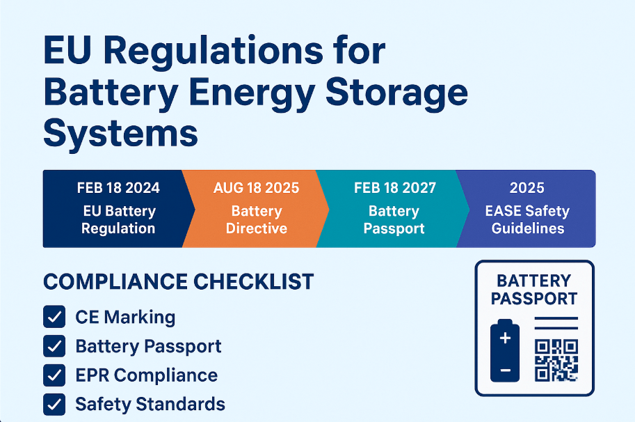
EU Battery Regulation 2023/1542 — Adds carbon footprint declaration and Digital Battery Passport from 2024
Machinery Directive 2006/42/EC — Applies if the BESS includes any motorized or moving parts
2026 EU Update: The EU Battery Regulation adds a Digital Battery Passport for BESS above 2 kWh. From 2027, every qualifying battery needs a QR-code-linked passport with carbon footprint and supply chain data. Start compliance preparation now.
D. BIS Certification — India
In India, the Bureau of Indian Standards (BIS) manages mandatory BESS certifications under the Compulsory Registration Scheme (CRS). Without BIS registration, products cannot clear customs or qualify for government tenders. India is a fast-growing BESS market, so this certification is increasingly important.
IS 16270:2014 — Safety for lithium-ion cells, equivalent to IEC 62133
IS 17855:2022 — Stationary lithium battery safety, aligned with IEC 62619
IEC 62619 (adopted directly) — Required for large-scale utility and industrial BESS tenders
Testing must be done at BIS-approved labs or internationally accredited labs with a BIS agreement. Additionally, registration is model-specific and must be renewed. Typical timeline: three to six months.
E. CEC Approval — Australia
Australia’s Clean Energy Council (CEC) governs BESS certifications for the Australian market. CEC listing is required for grid connection and STC rebate eligibility. Without it, network operators will not approve the connection.
AS/NZS 5139:2019 — Australian standard for battery systems with power conversion equipment
CEC Approved Product List — Products must appear on this list before any grid connection
Installer accreditation — CEC Battery Storage Accreditation is required for all installers
F. NFPA 855 — USA Fire Installation Standard
NFPA 855 governs how BESS certifications translate into safe real-world installations. While UL 9540 covers product safety, NFPA 855 covers how and where BESS is installed. Many US states have adopted it into local building codes.
Sets maximum energy capacity per room and building type
Requires fire suppression systems above defined energy thresholds
Mandates separation distances between battery racks and modules
Requires UL 9540A unit-level results as part of the permit application
Therefore, project developers must design installations to NFPA 855 from day one. Failing to do so results in permit denial — often after costly design work is already complete. For a deeper look into compliance steps, spacing rules, and permitting, read our Complete NFPA 855 Guide.
G. UN 38.3 — International Transport Certification
UN 38.3 is one of the most universally required BESS certifications — yet it is often overlooked. Simply put, it is the mandatory transport safety test for all lithium batteries shipped internationally. Without a valid UN 38.3 report, your shipment will be refused by airlines, shipping lines, and road carriers.
Tests include altitude simulation, thermal testing, vibration, shock, short circuit, and overcharge
Required under IATA (air), IMDG (sea), and ADR/RID (road) dangerous goods regulations
Cells, modules, and complete packs each need separate UN 38.3 documentation
Must be done at an accredited laboratory — self-certification is not accepted
Warning: Outdated or cell-only UN 38.3 reports are very common from lower-tier manufacturers. Any design change — including a new BMS version or different cell count — requires a fresh test. Check validity before every shipment.
4. System-Level vs. Component-Level BESS Certifications
Many buyers assume that a certified component means a certified system. In practice, this is wrong. Every level of a BESS assembly needs its own BESS certifications. Moreover, any change to a component — even a firmware update — can invalidate the existing system certificate.
Component
Relevant BESS Certifications
Why Independent Certification Is Required
Individual cells
UN 38.3, IEC 62133, UL 1973
Cell chemistry, abuse tolerance, and transport safety
Battery module
UL 9540A (cell level), IEC 62619
Module-level thermal runaway fire propagation
Battery pack / rack
UL 9540A (module level), IEC 62619
Pack-level fire propagation and structural safety
BMS
IEC 61508, UL 991
Software functional safety and fault detection logic
PCS / Inverter
UL 1741, IEC 62109, CE LVD
Grid interaction, isolation, and anti-islanding protection
Full assembled system
UL 9540, UL 9540A (unit), CE, IEC 62933
System integration, fire safety, and grid compliance
For this reason, always request the full system-level test report. It must list the exact model numbers, BMS version, cell supplier, and test configuration — matching the product you will actually receive.
5. Factory Certifications That Support BESS Certifications
Product BESS certifications are only part of the picture. The factory itself also needs to meet recognized management standards. Without factory certification, there is no reliable batch traceability — and no accountability when problems arise after delivery.
Certificate
What It Proves
Relevance to BESS Buyers
ISO 9001:2015
Quality Management System
Consistent production quality and batch traceability
ISO 14001:2015
Environmental Management System
Safe handling and disposal of hazardous battery materials
ISO 45001:2018
Occupational Health and Safety
Worker safety in battery manufacturing environments
IATF 16949
Automotive-grade quality standard
Relevant for BESS using automotive-grade LFP or NMC cells
ISO/IEC 27001
Information Security Management
Required for grid-connected BESS with SCADA or IoT systems
6. How to Spot Fake or Invalid BESS Certifications
Fraudulent BESS certifications are surprisingly common — especially in the Chinese supply chain. As a result, buyers who do not know what to check often accept invalid documents. Here are the key red flags to look for:
Cell-only report shown as a system cert: Supplier shows IEC 62619 for the cell but has no system-level UL 9540 or CE Declaration
Wrong model number: The certified model is different from the product being shipped to you
Expired documents: Check the issue date and validity period on every certificate — expired certs are invalid
Unknown test lab: Lab is not listed under ILAC mutual recognition — verify at ilac.org
Missing UL 9540A unit-level test: Only cell-level results are shown; module and unit levels are absent
No Technical Construction File for CE: Self-declaration is legal, but the Technical File must exist and be available
Supplier refuses to verify: UL certs are verifiable at iq.ul.com — refusal to verify is a serious warning sign
7. BESS Certifications Cost and Timeline Overview (2026)
Budgeting early for BESS certifications is essential. Costs vary by lab, system complexity, and region. Furthermore, any change to chemistry, BMS software, or module count after certification may trigger re-testing. These are approximate benchmarks for 2025 to 2026:
BESS Certification
Approx. Cost (USD)
Timeline
Key Notes
UL 9540 — full system
$80,000 – $200,000+
6–12 months
Includes UL 9540A at all three levels
UL 9540A — thermal runaway
$30,000 – $80,000
3–6 months
Cell, module, and unit tested separately
IEC 62619
$15,000 – $40,000
3–5 months
Available at TÜV, SGS, Intertek globally
CE Marking (LVD + EMC)
$10,000 – $30,000
2–5 months
Notified body fees vary by complexity
BIS India — IS 17855
$5,000 – $15,000
3–6 months
Testing at BIS-approved or linked labs
CEC Australia
$5,000 – $20,000
2–4 months
Requires ISO 17025 accredited lab report
UN 38.3
$3,000 – $8,000
4–8 weeks
Required per battery model and configuration
ISO 9001 factory cert
$5,000 – $20,000/yr
3–6 months
Annual surveillance audits required
8. BESS Certification Buyer’s Checklist — Before You Sign
Navigating a BESS purchase requires a structured phase-by-phase compliance review before signing any final purchase agreement or paying a deposit. The process begins at the fundamental component level, where buyers must verify cell and module abuse integrity under standards like UL 1973 and UL 2580. Ensuring your hardware meets EV-grade physical ruggedness standards heavily mitigates the risk of localized cell failures cascading into full-scale thermal runaway down the line.
Once component safety is established, the focus transitions directly to integration within the complete enclosure architecture. System developers must verify that the full assembly carries UL 9540 certification and that the manufacturer provides a comprehensive UL 9540A report detailing fire propagation limits across all three testing tiers: cell, module, and unit level. This step is critical for securing local installation permits and satisfying authority requirements.
The next milestone involves transitioning the physical hardware into an active electrical grid, which introduces strict performance and stability criteria. Developers should look to international frameworks like IEC 62933-2-1 to validate real-world parameters such as full-system round-trip efficiency (RTE) and step response time, while utilizing IEC 62933-5-2 to confirm that the internal battery management system (BMS) logic can safely handle external grid faults or sudden frequency shifts. For a complete deep dive into these electrical parameters, review our comprehensive breakdown of IEC Certifications for BESS.
For projects crossing international borders, distinct regional and maritime regulations must be cleared well before commissioning. Entering European markets requires a formal CE Marking Declaration of Conformity covering low voltage, electromagnetic compatibility, and the latest digital battery passport index mandates—detailed thoroughly in our guide to CE for BESS Certification. Concurrently, deployments targeting specific local markets must secure specialized domestic registrations, such as BIS Certification for Lithium-Ion Batteries for clearing Indian customs or Clean Energy Council (CEC) approved listing to grant grid connection and rebate eligibility in Australia.
Finally, logistics and long-term project lifecycles must be factored into the initial risk assessment. Every international lithium battery shipment—regardless of the target destination—legally requires a valid, model-specific UN 38.3 transport safety report covering severe vibration, altitude, and shock testing to prevent carrier rejection at port. Successfully validating these layers chronologically ensures that your asset arrives safely, passes inspection smoothly, and maintains accurate end-of-life calculations over its entire 10-to-15-year lifecycle.
9. Frequently Asked Questions About BESS Certifications
Here are the most-searched questions about BESS certifications, with direct and clear answers.
What certifications does a BESS need in the United States?
In the USA, BESS certifications include UL 9540 for the full system, UL 9540A at cell/module/unit levels, UL 1973 for battery packs, and UL 1741 for the inverter or PCS. Additionally, all US installations must comply with NFPA 855 and NEC Article 706.
Is UL 9540 mandatory for BESS in the USA?
Yes — in practice. UL 9540 is technically a voluntary standard. However, it is required by most state building codes, utility interconnection agreements, and insurance policies. Without it, your system will not be permitted or connected to the grid.
What is the difference between UL 9540 and UL 9540A?
UL 9540 is the full product safety standard for a complete BESS system. UL 9540A, however, is a specific test for fire propagation during a thermal runaway event. In other words, UL 9540A is a prerequisite test that must be passed before UL 9540 listing is granted.
Can I sell BESS in Europe without CE Marking?
No. CE Marking is a legal requirement for all electrical products in the EU and EEA. Products without it can be seized at the border. Furthermore, from 2024, the EU Battery Regulation adds extra compliance requirements beyond traditional CE directives.
Does IEC 62619 replace UL 9540?
No — they serve different purposes. IEC 62619 is a component-level standard for lithium battery safety. UL 9540, on the other hand, is a full system safety standard specific to the US market. For US sales you need UL 9540. For global acceptance, IEC 62619 is the recognized baseline.
What is UN 38.3 and is it required for BESS shipments?
UN 38.3 is the mandatory transport safety test for all lithium batteries. It is required for every international shipment of cells, modules, and packs — by air, sea, or road. Without a valid UN 38.3 report, freight forwarders and customs will reject the shipment.
How long does BESS certification take from start to finish?
Full UL 9540 certification takes six to twelve months. IEC 62619 takes three to six months. CE Marking can be completed in two to five months. UN 38.3 is the fastest at four to eight weeks. Most manufacturers apply for several certifications at the same time to reduce total time to market.
What is the EU Battery Passport and when does it apply?
The EU Battery Regulation (2023/1542) introduces a Digital Battery Passport for industrial BESS above 2 kWh sold in the EU. From 2027, each qualifying battery needs a QR-linked passport with carbon footprint and supply chain data. As a result, BESS manufacturers targeting Europe should start compliance preparation immediately.
Related Articles and Useful Links
Add these internal links when publishing on WordPress — they strengthen topical authority and support navigation:
As the world shifts towards renewable energy, the need for efficient energy storage systems is greater than ever. Battery Energy Storage Systems (BESS) are at the center of this transformation. But not all BESS setups are the same. One important configuration to understand is the DC Coupled BESS. In this blog post, we will explore what it is, how it works, its key components, and why it can be a smart choice for many renewable energy projects.
What is a DC Coupled BESS?
A DC Coupled Battery Energy Storage System (BESS) is an energy storage architecture where both the battery system and solar photovoltaic (PV) panels are connected on the same DC bus, before the inverter. This is different from an AC coupled BESS, where the solar and battery systems are each connected to the AC grid separately via their own inverters.
In simpler terms, in a DC-coupled system, the solar panels and battery share one inverter and connect through a DC/DC converter. This makes the system more efficient, especially in applications where solar generation is paired with energy storage.
Core Components of a DC Coupled BESS System
A typical DC coupled BESS includes the following major components:
1. Solar PV Array
Captures sunlight and converts it into direct current (DC) electricity.
2. DC/DC Converter
This device regulates the voltage between the PV panels, battery, and inverter. It allows maximum power point tracking (MPPT) and enables energy flow between the PV and battery.
3. Battery Pack
Stores excess solar energy for use during periods of low generation or peak demand. Common chemistries include Li-ion (NMC, LFP) and semi-solid batteries.
4. Battery Management System (BMS)
Monitors and protects the battery cells. It manages parameters like voltage, current, temperature, and SoC (state of charge).
5. Hybrid Inverter (DC to AC)
Converts DC electricity from the battery or solar panels into AC electricity for use in homes, industries, or to feed into the grid.
6. Energy Management System (EMS)
Controls the operation of the entire system, optimizing charging/discharging, solar usage, and grid interaction based on pre-set algorithms and real-time conditions.
DC-Coupled Battery Storage: Why It’s More Efficient
DC-coupled battery storage keeps the solar array and battery on the same DC bus, so they share one inverter instead of each needing their own. That single shared conversion point is what defines DC-coupled energy storage and separates it from AC-coupled designs.
Because the battery in a DC-coupled battery storage system charges directly from the DC bus, it can also capture solar energy that would otherwise be clipped when panel output exceeds what the inverter can push to the grid — a common limitation in high-output PV arrays. That stored energy would simply be wasted in a system without DC-coupled storage in place. NREL’s 2024 Annual Technology Baseline applies a dedicated “Co-location Savings Rate of DC-Coupled Systems” in its own cost modeling for utility-scale PV-plus-battery projects, reflecting the added value this shared-inverter design captures over standalone PV and storage.
The Role of the BESS Inverter (PCS) in a DC-Coupled System
In a DC-coupled BESS, the shared inverter is often called the Power Conversion System, or PCS, in utility-scale and C&I applications. Because the solar array and battery share the same DC bus, this single BESS inverter has to manage three jobs at once: routing DC power between PV, battery, and loads; converting DC to AC at the one point where stored or generated energy leaves the DC bus; and, in some designs, forming or following grid voltage and frequency.
Because DC-coupled systems route everything through one inverter, PCS sizing and certification carry more weight here than in an AC-coupled design, where the load splits across two smaller units.
Here’s a simplified step-by-step overview of how a DC Coupled BESS operates:
During Daytime with Sunlight:
Solar PV generates DC electricity.
DC power goes to the DC/DC converter.
Part of the energy is used directly by loads (via inverter).
Excess energy charges the battery via the same DC bus.
Only one DC to AC conversion occurs when sending power to the grid or loads.
During Night or Cloudy Periods:
Stored energy in the battery is sent through the inverter to supply the AC load or the grid.
Grid-Tied and Off-Grid Modes:
Can function in both modes, depending on the design.
Can seamlessly switch between grid usage, solar generation, and battery power based on EMS logic.
Benefits of DC Coupled BESS
DC coupled systems offer several technical and economic advantages over AC coupled ones:
1. Higher Efficiency
Fewer conversions (DC-AC-DC in AC coupled vs. just DC-AC here).
Reduces energy losses, improving overall round-trip efficiency.
2. Lower Equipment Cost
Only one inverter needed.
Fewer transformers and conversion stages reduce capital expenditure.
3. Maximized Solar Harvesting
Allows solar charging even during grid outages.
Can store excess energy that would otherwise be clipped or curtailed.
4. Improved System Integration
Easier to integrate solar, battery, and EV charging into one system.
Easier to control and manage with centralized EMS.
5. Simpler Grid Interconnection
Since everything passes through a single inverter, grid interconnection rules are simpler.
Reduces the complexity of interconnection studies and permits.
6. Faster Response Time
Direct DC connection between battery and PV allows faster power adjustments in response to load changes or frequency events.
When Should You Choose a DC Coupled BESS?
A DC Coupled BESS is ideal for:
New solar + storage installations where both systems are designed together.
Remote or off-grid locations where grid stability and efficiency are critical.
Microgrid systems requiring smooth integration of multiple power sources.
Commercial and industrial setups looking for energy savings and peak load shaving.
However, if you’re retrofitting an existing solar system, an AC-coupled system is often easier to implement since it doesn’t require touching your existing PV wiring. For the full breakdown of both architectures — cost, efficiency, retrofit fit, and when to choose each — see our complete guide: AC-Coupled vs. DC-Coupled BESS: Which Architecture Is Right for Your Project?
Frequently Asked Questions
What does “DC-coupled” mean?
“DC-coupled” means the solar PV array and the battery connect to the same DC bus, ahead of a single shared inverter, rather than connecting separately on the AC side.
How does DC-coupled energy storage work?
Solar PV generates DC power that flows through a DC/DC converter, where it either charges the battery directly or passes through the shared inverter to supply AC loads or the grid. Because charging and discharging both happen on the DC side, the system converts power to AC only once, which improves efficiency compared to AC-coupled designs.
What does BESS stand for?
BESS stands for Battery Energy Storage System — any system that stores electrical energy in batteries for later use, whether paired with solar, wind, or the grid.
What is a DC-coupled battery?
A DC-coupled battery is a battery wired directly to the same DC bus as the solar array, charging and discharging through a shared DC/DC converter and inverter instead of its own dedicated inverter.
What’s the difference between AC-coupled and DC-coupled BESS?
A DC Coupled BESS offers a more efficient, cost-effective, and integrated approach to combining solar and battery storage. By reducing the number of conversions and simplifying system design, it ensures higher performance and better return on investment, especially in new or greenfield projects.
As energy needs evolve and distributed energy resources grow, understanding these architectures becomes critical. Whether you’re a developer, EPC, or energy investor—DC coupled systems could offer you the next level of performance and reliability.